1
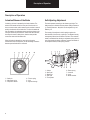
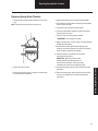
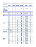
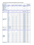
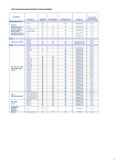
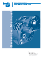
Premium wheel-end brake products
Service Manual
Bendix® ESD-225™ Air Disc Brake
Table of Contents
Replacing Disc Brake
Removing Disc Brake Caliper . . . . . . . . . . . . . . 19
Replacing Disc Brake Caliper . . . . . . . . . . . . . . 19
Specifications
Disc Brake ESD225 . . . . . . . . . . . . . . . . . . . . . . . 4
Tightening Torque. . . . . . . . . . . . . . . . . . . . . . . . . 5
Wear Limits . . . . . . . . . . . . . . . . . . . . . . . . . . . . . 5
Replacing Slide Pins, Slide Bushings, and Boots
Removing Slide Pins, Slide Bushings,
and Boots. . . . . . . . . . . . . . . . . . . . . . . . . . . . . . 20
Inspection. . . . . . . . . . . . . . . . . . . . . . . . . . . . . . 22
Replacing Slide Bushings and Slide Pins . . . . . 22
Replacing Boots in Caliper. . . . . . . . . . . . . . . . . 23
Description of Operation
Actuation/Release of the Brake . . . . . . . . . . . . . .
Self-Adjusting Adjustment . . . . . . . . . . . . . . . . . .
Application . . . . . . . . . . . . . . . . . . . . . . . . . . . . . .
Release . . . . . . . . . . . . . . . . . . . . . . . . . . . . . . . .
6
6
7
8
Safety Instructions . . . . . . . . . . . . . . . . . . . . . . . . 10
Service Instructions
Service Intervals. . . . . . . . . . . . . . . . . . . . . . . . .
Checking Pads. . . . . . . . . . . . . . . . . . . . . . . .
Checking Brake Disc . . . . . . . . . . . . . . . . . . .
Checking Sliding Function . . . . . . . . . . . . . . .
Checking Play in the Slide Pins . . . . . . . . . . .
Checking Boots for Slide Pins . . . . . . . . . . . .
Checking Bellows for Adjustment Screws . . .
Operating Test . . . . . . . . . . . . . . . . . . . . . . . . . .
Initial Adjustment . . . . . . . . . . . . . . . . . . . . . . . .
Lubrication . . . . . . . . . . . . . . . . . . . . . . . . . . . . .
General . . . . . . . . . . . . . . . . . . . . . . . . . . . . .
Adjustment Mechanism . . . . . . . . . . . . . . . . .
Slide Pins and Bushings . . . . . . . . . . . . . . . .
11
12
12
13
13
14
14
15
16
16
16
16
16
Replacing Brake Chamber
Removing Brake Chamber. . . . . . . . . . . . . . . . . 25
Replacing Brake Chamber . . . . . . . . . . . . . . . . . 25
Replacing Spring Brake Chamber
Removing Spring Brake Chamber . . . . . . . . . . . 26
Replacing Spring Brake Chamber . . . . . . . . . . . 27
Replacing Rotor
Removing Rotor . . . . . . . . . . . . . . . . . . . . . . . . .
Replacing Rotor . . . . . . . . . . . . . . . . . . . . . . . . .
Rotor Runout Check. . . . . . . . . . . . . . . . . . . . . .
Cleaning and Inspection. . . . . . . . . . . . . . . . . . .
Rotor Resurfacing . . . . . . . . . . . . . . . . . . . . . . .
28
28
28
29
29
Troubleshooting . . . . . . . . . . . . . . . . . . . . . . . . . . 30
Replacing Pads
Removing Pads . . . . . . . . . . . . . . . . . . . . . . . . . 17
Replacing Pads . . . . . . . . . . . . . . . . . . . . . . . . . 17
Initial Adjustment . . . . . . . . . . . . . . . . . . . . . . . . 18
1
Table of Contents
General Information
Model Identification . . . . . . . . . . . . . . . . . . . . . . . 2
Exploded View . . . . . . . . . . . . . . . . . . . . . . . . . . . 3
General Information
Model Identification
Bendix ESD - 225™
®
Wheel Size
Disc Brake
Extended Service
2
General Information
Product Identification – Exploded View
5
6
7
8
20
General Information
21
22
12
14
19
23
11
13
4
10
9
18
17
Exploded view of conventional hub rotor
1
2
24
25
1 – Torque plate
2 – Carrier
4 – Caliper Assy.
5 – Retaining bar screw
6 – Retaining bar
7 – Pad retaining spring
8 – Pads
9 – Slider boot
10 – Boot retaining ring
11 – Slider bushing
12 – Slide pin
26
13 – Slider pin bolt
14 – Slider pin cap
17 – Flat washer
18 – Hex head screw (torque plates to frame)
20 – Air chamber
21 – Air chamber nut & air chamber washer
22 – Actuator plug
23 – Actuator assembly extension
24 – Rotor
25 – Rotor mounting cap screw
26 – Hub
3
Specifications
Specifications
Disc Brake ESD225
METRIC
4
STANDARD
Max. brake chamber force
13.9 kN
3124.8 lbf.
Wheel size
571.5 mm
22.5 in.
Number of actuating pistons
2
2
Number of slide pins
4
4
Threshold force
28N
6.3 lbf.
Brake chamber stroke requirements
min. 57 mm
min. 2.2 in.
max. 65 mm
max. 2.6 in.
Mechanical advantage
15:8:1
15:8:1
Max. adjustment distance brake lining
58 mm
2.3 in.
Lining thickness (friction material), new
22 mm
0.9 in.
Backplate thickness
8 mm
0.3 in.
Running clearance brake lining to brake disc
0.6 - 0.8 mm
0.02 - 0.03 in.
External diameter brake disc
430 mm
16.9 in.
Thickness brake disc, new
45 mm
1.8 in.
Thickness brake disc, worn
41 mm
1.61 in.
Effective radius
172.6 mm
6.8 in.
Swept area, brake disc
1808 cm
280.2 cm2
Lining area (per pad)
187 cm2
Grease (GGLB - NGLI +350°F/+177°C to -35°F/-37°C
Standard Chassis Grease
Weight, disc brake, approximately. (Exc. brake disc/pads/chamber and sensor)
42.0 Kg
2
29.0 cm2
112.5 lb.
Specifications
Tightening Torque
Wear Limits
Torque fasteners to specifications in table.
Fastener
Frame Mounting Screw*
Slide Pin Screw
Retaining Bar Screw
Actuator Mounting Screw
Bridge Mounting Screw
Air Chamber
Rotor to Iron Hub
(use Loctite 266)
Rotor to Aluminum Hub
Torque
N•m
447 to 474
187 to 200
42 to 48
24 to 30
100 +/-10 +50º
+/-2º turn
176
339 to 373
Torque
lbs. ft.
330 to 350
138 to 148
31 to 35
18 to 22
74 +/-7 +50º
+/-2º turn
130
250 to 275
190 +/- 19
140 +/- 14
Pads, min. lining thickness
Pads, max. uneven wear
Slide pins, max. play
Brake disc, max. wear per
side
Brake disc, max. lateral
runout
Brake disc, max.
thickness variation
METRIC
3 mm
1 mm
1 mm
2 mm
STANDARD
0.12 in.
0.04 in.
0.04 in.
0.08 in.
0.5 mm
0.02 in.
0.1 mm (DTV)
0.004 in.
*Use the Snap-on™ Torque Wrench Heavy Duty Offset 13/16"
(30mm) Box Adapter (part number XM300B) with the Snap-on™
400 lbs. ft. Torque Wrench (part number TQR400).
Snap-on™ Customer Service – 877-740-1900
Specifications
5
Description of Operation
Description of Operation
Actuation/Release of the Brake
Self-Adjusting Adjustment
On braking, the lever is actuated by the brake chamber. The
external and internal radii of the inner part of the lever do not
have a common center, which means that the crossbar is moved
axially in the direction of the brake disc. The force is transferred
from the crossbar via adjustment screws and thrust plates to the
inner pad. When the pad comes into contact with the brake disc,
the caliper is moved on slide pins so that the outer pad also
comes into contact with the brake disc.
The brake operates according to the clearance principle. The
brake sequence is divided into three phases: Design Clearance
- C, Excess Clearance - Ce (which is to be adjusted out), and
Elasticity - E.
When the brake is released, the return spring forces the
crossbar back into its rest position, so that the design clearance
between pad and brake disc is achieved.
The housing of the adjuster is held in position against the
internal radius of the lever by a guide pin. The adjuster housing
consequently follows the movement of the lever. The rotational
motion is transferred from housing to adjustment spring which in
turn, after passing the design clearance, transmits the motion of
the companion sleeve, friction spring and hub.
E Ce C
1
2
3 4
3/3 2/3 1/3
5
1 – Guide pin
2 – Adjustment spring
3 – Companion Sleeve
6
4 – Friction spring
5 – Hub
6 – Adjuster housing
1 – Caliper
2 – Outer pad
3 – Brake disc
4 – Inner pad
5 – Thrust plates
6
7
8
6 – Return spring
7 – Crossbar
8 – Lever
9 – Brake chamber
9
Description of Operation
Application
C - During the movement through C, the design clearance is
measured between the pad and brake disc by the adjuster.
There is a predetermined clearance between the tongue of the
adjustment spring and the slot in the companion sleeve, which
determines the free stroke before the adjustment.
Ce - If excess clearance remains after the mechanism has
moved radially in accordance with the design clearance C, the
adjuster, synchronization shaft, pinions, crown wheels, adjusting
shaft/readjustment shaft and the adjustment screws are turned.
The rotation of the adjustment screws means that a percentage
of the measured excess Ce is removed.
In the adjuster, the turning movement is transferred from the
housing via the adjustment spring, companion sleeve, and
friction spring to hub, which engages with the synchronization
shaft.
4
5
6
E Ce C
3/3 2/3 1/3
E Ce C
7
1 – Adjustment spring
2 – Companion sleeve
3 – Adjuster
4 – Outer pad
5 – Brake disc
6 – Inner pad
7 – Adjuster
3/3 2/3 1/3
7
1 – Adjuster
2 – Adjuster spring
3 – Housing
4 – Companion sleeve
8
5 – Friction spring
6 – Hub
7 – Synchronization shaft
8 – Adjuster
Description of Operation
7
Description of Operation
E - When the two (2) pads come into contact with the brake
disc, the braking sequence enters elasticity phase E, the torque
rises and the adjuster stops adjusting. The continued rotational
movement, which now occurs in the adjuster is allowed by
rotating the housing in relation to the adjustment spring.
Release
The first part of the return stroke passes through C followed by
movement corresponding to E and Ce. During the return stroke,
the return spring ensures that the crossbar travels back.
C - During the first part of the return stroke, transmitted force
decreases and the tongue of the adjustment spring changes
flank in the slot of the companion sleeve.
4
5
6
E Ce C
C E Ce
3/3 2/3 1/3
1 – Adjustment spring
2 – Rotating housing
3 – Adjuster
4 – Outer pad
5 – Brake disc
6 – Inner pad
3/3 2/3 1/3
1 – Adjustment spring
2 – Companion sleeve
8
Description of Operation
E - The next part of the return stroke corresponds to E. The
housing of the adjuster, the adjustment spring and companion
sleeve are rotated in relation to the hub, which is stationary.
Movement between companion sleeve and hub is allowed by
the friction spring.
Ce - During the last part of the return stroke (Ce), the rotational
movement continues in the adjuster as described under E until
the mechanism has reached its resting position. The friction
springs on the adjustment screws prevent the mechanism from
backing off.
C E Ce
6
E Ce C
3/3 2/3 1/3
3/3 2/3 1/3
1
1 – Adjuster
4 – Friction spring
5 – Hub
6 – Inner pad
Description of Operation
Brake torque
1 – Adjustment spring
2 – Rotating housing
3 – Companion sleeve
Adjustment
phase (Ce)
Free stroke
Elasticity
9
Safety Instructions
Safety Instructions
• Always follow the vehicle manufacturer's safety instructions
when working on a vehicle.
• Follow the vehicle manufacturer's instructions for jobs which are
not described in this manual.
• Follow local safety regulations.
! DANGER
AVOID CREATING DUST
POSSIBLE CANCER AND LUNG
DISEASE HAZARD
• The work must be carried out by trained personnel.
• Sudden release of tensioned springs, such as the spring brake
part of the brake chamber and the return spring of the disc
brake, may cause injury.
• Use recommended tools only.
• Release pressure from lines and components before opening
them.
• Chock at least one of the vehicle's wheels to prevent involuntary
movement of the vehicle.
• Before releasing the vehicle back in service, perform a brake
operational check and test drive the vehicle to make sure that
the brakes are working correctly.
While Bendix Spicer Foundation Brake LLC does
not offer asbestos brake linings, the long-term
effects of some non-asbestos fibers have not
been determined. Current OSHA Regulations
cover exposure levels to some components of
non-asbestos linings but not all. The following
precautions must be used when handling these
materials.
1. AVOID CREATING DUST. Compressed air or dry
brushing must never be used for cleaning brake
assemblies or the work area.
2. BENDIX SPICER FOUNDATION BRAKE LLC
RECOMMENDS THAT WORKERS DOING
BRAKE WORK MUST TAKE STEPS TO MINIMIZE
EXPOSURE TO AIRBORNE BRAKE LINING
PARTICLES. Proper procedures to reduce
exposure include working in a well ventilated area,
segregation of areas where brake work is done,
use of local filtered ventilation systems or use of
enclosed cells with filtered vacuums. Respirators
approved by the Mine Safety and Health
Administration (MSHA) or National Institute for
Occupational Safety and Health (NIOSH) should
be worn at all times during brake servicing.
3. Workers must wash before eating, drinking or
smoking; shower after working, and should not
wear work clothes home. Work clothes should be
vacuumed and laundered separately without
shaking.
4. Material safety data sheets on this product, as
required by OSHA, are available from Bendix
Spicer Foundation Brake LLC.
10
Service Instructions
Service Instructions
Service Instructions
Service Intervals
Check the following items regularly every 6 months. Refer to the
sections as listed below.
• Check brake pads
• Check brake disc
• Check caliper sliding function
• Check operation
!
WARNING: Refer to Safety Instructions. The vehicle
manufacturer's instructions must also be followed.
Clean the disc brake of dirt and dust. Use the specified type of
dust-removal equipment to clean, not compressed air, inhaling dust
particles may be harmful to health.
If the disc brake is equipped with a spring brake chamber, ensure
that the spring is caged in accordance with the manufacturer's
instructions.
11
Service Instructions
Checking Pads
Measure the distance from the backplate to the wearing surface
of the pad.
Measure the lateral runout of the brake disc as
follows.
The minimum permitted lining thickness (friction material), per
D.O.T. (Department of Transportation) standards, is currently
3 mm (.12 in). (The lining thickness of a new pad is 22 mm
(0.9 in.).) Replace the pads if they are worn out.
1. Attach a magnetic stand, complete with a dial indicator on the
frame.
Check that the pads are evenly worn by measuring at four
different points on the pad. A maximum of 1 mm [0.04 in.] of
uneven wear is allowed. Also, the inner and outer pads must
be worn equally. In the event of uneven wear, check the sliding
function of the caliper on the slide pins. See "Checking Sliding
Function".
2. Place the tip of the dial indicator on the face of the brake disc.
3. Rotate the brake disc. Max. runout 0.5 mm
[0.02 in.].
IMPORTANT: Do not include the wheel bearing play in the
measurement.
IMPORTANT: Driving with light braking may result in increased
wear on the inner brake lining.
To replace the pads, see the section on "Replacing Pads".
Checking Brake Disc
Measure the thickness of the brake disc. Minimum thickness of
the brake disc is 41 mm (1.61 in.).
1. If the brake disc has a worn edge, the measurement can be
performed using two (2) spacers.
2. Reduce the measured dimension by the total thickness of the
two (2) spacers.
1
2
1
1 – Carrier
2 – Brake disc
3 – Dial indicator
3
2
Refer to WESM-0060 for bearing adjustment
procedures. Endplay not to exceed .005 in.
Also check the brake disc for cracks and wear tracks.
1 – Spacers
2 – Brake disc
12
Service Instructions
Checking Play in the Slide Pins
This check is done after the pads have been removed. See the
section on "Replacing Pads".
Measure the play in the outer slide pins as follows. The
maximum amount of play is 1.0 mm [0.04 in.].
Check the sliding motion of the caliper on the slide pins. If the
caliper does not slide freely on the pins, make sure the movement is not obstructed by external dirt or foreign objects.
1
Service Instructions
Checking Sliding Function
1. Attach a magnetic stand, complete with a dial indicator to
the frame.
2. Put the tip of the dial indicator on caliper at point 2, see
below.
3. Rock the caliper and read the dial.
4. Repeat this measurement procedure inside the brake disc for
the inner slide pins and measure at point 5, see below.
6
5
2
4
3
1 – Caliper
1
1 – Outer slide pin
2 – Dial indicator tip
3 – Inner slide pin
4 – Carrier
5 – Measure point
6 – Dial indicator
13
Service Instructions
Checking Boots for Slide Pins
Checking Bellows for Adjustment Screws
Check the protection caps and rubber boots of the slide pins
[two (2) per slide pin]. If there are signs of cracks or other
damage on the rubber bellows and protection caps, they
must be replaced.
1. Using an 8 mm socket, rotate the readjustment shaft until the
protection springs are fully visible.
If action is required, see the section on "Replacing Slide Pins,
Slide Bushings and Boots".
2. Inspect the protection springs. The protection springs must be
replaced if there are signs of cracks or other damage.
IMPORTANT: Thrust plates should not exceed 50 mm
[1.97 in.] from the cover.
3. Pull back the protection springs and inspect the rubber
bellows. The rubber bellows must be replaced if there are
signs of cracks or other damage.
4. Turn back the readjustment shaft. Do not tighten the shaft.
If action is required, see section "Replacing Disc Brake".
3
2
2
1
1 – Slide pin protection cap
2 – Slide pin rubber boots
Max.
50 mm
[2.2 in.]
1 – Thrust plates
2 – Cover
3 – Protection springs
14
1
Service Instructions
1. Lift and support the axle in accordance with the vehicle
manufacturer's instructions.
!
WARNING: Follow the Safety Instructions. The vehicle
manufacturer's instructions must also be followed.
6. Leave the wrench in the same position.
7. Activate the brakes five (5) times. The wrench must move on
each brake application which shows that the self-adjustment
is working.
2. Check that the wheel can be turned freely.
3. Remove the plug.
4. Release the brake by turning the readjustment shaft using
an 8 mm socket (3/4 turn).
Note: The brake can be released in the counterclockwise
direction.
5. Position disc brake with the brake chamber at the top
and viewed from the side on which the hexagon of the
readjustment shaft is accessible, turn the readjustment
shaft counterclockwise.
IMPORTANT: Movement of the wrench must not be
obstructed. If the wrench moves to and fro or does not move
at all, the caliper is defective and must be replaced.
See the section on "Replacing the Disc Brake".
Release
Counterclockwise
x5
15
Service Instructions
Operating Test
Service Instructions
Initial Adjustment
1. Check that the brake disc can be turned freely.
Lubrication
!
WARNING: Follow the Safety Instructions. The vehicle
manufacturer's instructions must also be followed.
General
To obtain maximum service life, it is important to use only the
specified lubricants for the lubrication points concerned.
Apply the correct amounts. To prevent the lubricant from being
dispersed or causing damage during the natural movements
of the brake (e.g., on friction surface of pads, on brake disc, in
boots and bellows, etc.), do not apply excessive amounts of
lubricant.
Adjustment Mechanism
1
1 – Brake disc
The adjustment mechanism is lubricated and sealed for life in
the factory.
Slide Pins and Bushings
2. Using an 8 mm socket, turn the readjustment shaft clockwise
(Do not force) until both pads touch the brake disc.
3. Loosen the readjustment shaft 1/2 turn counterclockwise to
obtain a basic clearance between the pads and the brake
disc.
4. Check that the brake disc can be turned freely.
5. Remove the wrench.
6. Fit the plug into the adjustment access hole on the
readjustment shaft. Make sure it is securely installed.
!
WARNING: To prevent damage to the adjusting
mechanism, never use an impact wrench. Do not
exceed 150 lbs. in. or damage to the adjuster
extension may occur.
Note: In order to obtain correct clearance between the brake
disc and the pads, the mechanism itself will perform
the final fine-adjustment during a number of braking
applications.
7. Lower the axle, remove the support and the wheel chocking
in accordance with the vehicle manufacturer's instructions.
16
Lubricate the slide pins and bushings sparingly during assembly.
See the section of "Specifications" for selection of the lubricant.
Use only the specified lubricant.
Replacing Pads
Removing Pads
Replacing Pads
• Always replace pads on both sides of the axle at the same time.
1. Using an 8 mm socket, turn counterclockwise until the
readjustment shaft is fully retracted.
!
WARNING: Follow the Safety Instructions. The vehicle
manufacturer's instructions must also be followed.
• Chock the wheels on an axle that is not to be raised.
• Lift the axle, support and remove the wheels in
accordance with the vehicle manufacturer's instructions.
WARNING: Clean the disc brake of dirt and dust. Use the
specified type of dust-removal equipment for cleaning. Do
not use compressed air. Inhaling dust particles may be
harmful to your health.
!
WARNING: If the disc brake is equipped with a spring
brake chamber, make sure that the spring is caged in
accordance with the manufacturer's instructions.
2. Check that the pad contact surfaces in the disc brake are
clean. Replace pads. Replace pad springs, retainer bar and
secure with retainer cap screw. Torque retainer cap screw to
45± 3 N•m [33.2 ± 2.2 lbs. ft.].
Replacing Pads
!
IMPORTANT: Do not tighten.
1. Remove the plug of the readjustment shaft.
2. Use an 8 mm socket to back off the brake adjuster. Turn the
readjustment shaft counterclockwise to release the brake. Do not
tighten.
IMPORTANT: To prevent damage to the adjusting mechanism,
never use an impact wrench.
3. Remove the retainer bar cap screw.
4. Remove the retaining bar. Hold the pad springs to prevent them
from jumping out.
5. Check the following (refer to section):
• Brake Disc
• Sliding Function
• Play in the Slide Pins
• Boots for Slide Pins
• Bellows for Adjustment Screws
17
Replacing Pads
Initial Adjustment
1. Check that the brake disc can be turned freely.
2. Using an 8 mm wrench, turn readjustment shaft until both
pads touch brake disc. Then loosen 1/2 turn to obtain a basic
clearance between pads and brake disc. Check that the brake
disc can be turned freely. Remove the socket or wrench.
1
1 – Brake disc
3. Fit plug into access hole readjustment shaft (see Item 1 in the
illustration below).
1
2
1 – Readjustment shaft
2 – Brake disc
!
18
CAUTION: Never use an impact wrench, as this could
damage the adjusting mechanism.
Note: In order to obtain correct clearance between
brake disc and pads, the adjusting mechanism
itself will perform the final fine-adjustment
during a number of braking operations.
Replacing Disc Brake
Removing Disc Brake Caliper
!
!
!
Replacing Disc Brake Caliper
1. Place caliper assembly on torque plate.
WARNING: Be sure to follow all safety instructions
including the blocking of wheels and proper lifting and
support of axle.
2. Lubricate attachment bolts with anti-seize compound.
3. Fit bolts through torque plate to caliper and tighten to snug
fit.
WARNING: Do not use compressed air.
4. Torque bolts to 330-350 lbs. ft. (407-448 N•m). If torque
wrench is not available, tighten bolt to snug fit (mark flat of
bolt to torque plate then tighten bolt one more flat). This will
be the approximate torque value.
WARNING: If disc brake is equipped with a spring
brake, make sure the spring is properly caged.
1. Remove air chamber from caliper and secure. Do not let the
air chamber hang by just the air hose.
2. Remove retaining bar.
3. Remove brake pads.
4. Re-install retaining bar and secure with fastener.
5. Connect lifting strap and suitable lifting device around retainer
bar.
1 Flat
(60 deg.)
6. Remove attachment bolts to torque plate.
5. Verify adjustment shaft is fully retracted.
IMPORTANT: Do not tighten.
6. Install Air Chamber. See page 25.
1
7. Check that the pad contact surfaces are clean.
9. Replace retaining bar and secure fastener.
10. Perform initial adjustment. See "Initial
Adjustment" on page 16.
1 – Readjustment shaft
Note: Make sure that the sliding function of the air chamber
does not pull on the ABS sensor. Chamber/caliper must be free
to slide inboard 20 mm (0.78 in.).
7. Remove caliper.
19
Replacing Disc Brake
8. Install new pads.
Replacing Slide Pins, Slide
Bushings, & Boots
Removing Slide Pins, Slide Bushings, and
Boots (Frame)
1. Put the disc brake assembly in a vise.
3. Remove the four (4) bolts for the slide pins using Torx E 18
socket.
3
2
1
2. Remove protection caps using a hammer and chisel. If the
inner part of the protection cap remains in the slide pin,
remove this using an internal bearing puller.
1 – Slide pins
2 – Caliper
Note: Protection caps must never be reused.
4. Retract the slide pins sufficiently to remove frame from caliper
by alternately pushing frame to and fro. If slide pins are
seized in the frame, cut threads internally in slide pins using
an M16x2 thread tap.
2
3
1
1 – Protection cap
2 – Carrier
20
3 – Caliper
3 – Carrier
!
WARNING: To prevent injury, only grip from outside.
Replacing Slide Pins, Slide
Bushings, & Boots
!
CAUTION: Do not use gripping tools, as the sealing
surfaces of the slide pins may be
damaged.
8. Remove the four (4) slide bushings (which are of a split
design) using a small screwdriver. Begin at the split.
IMPORTANT: Do not damage the fitting surfaces.
1
1
2
2
1 – Carrier
2 – Caliper
1 – Slide bearings (4)
2 – Caliper
5. Clean parts of dirt and dust.
!
WARNING: Use the specified type of dust removal
equipment to clean–not compressed air. Inhaling dust
particles may be harmful to health.
6. Press the four (4) slide pins out of the caliper.
7. Remove the eight (8) boots by carefully prying them out.
IMPORTANT: Do not damage the fitting surfaces.
1
Replacing Slide Pins, Slide
Bushings, & Boots
2
1 – Caliper
2 – Bellows (8)
21
Replacing Slide Pins, Slide
Bushings, & Boots
Inspection
Replacing Slide Bushings and Slide Pins
1. Check that the fitting surfaces for slide bushings and boots
are damage free.
1. Fit four (4) new slide bushings in caliper.
2. Lubricate slide bushings sparingly with grease.
3. Lubricate slide pins with grease and press them into
position in the slide bushing. Use Haldex tool #81921
(1-800-643-2374).
1
1
2
1 – Caliper
2 – Slide pins (4)
1 – Slide bearings (4)
4. Slide pins must slide easily in the slide bushings so that
caliper can "float" over carrier.
1
1 – Caliper
2 – Slide pins
22
2
Replacing Slide Pins, Slide
Bushings, & Rotors
Replacing Slide Pins, Slide
Bushings, & Rotors
Replacing Boots in Caliper
1. Install boot in caliper. Use Haldex tool #81922
(1-800-643-2374).
!
WARNING: To prevent injury, only grip from outside.
1
2. Press the outer part of boot into position in the groove in slide
pin and secure with boot ring.
3
4
2
2
1
1 – Lift carrier
2 – Caliper
1 – Caliper
2 – Slide pin
3 – Boot
4 – Boot ring
7. Apply anti-seize compound to the threads of the four (4) bolts
and screw them into position. Tighten with torque wrench
(Torx E 18 socket) to specs on page 5.
8. Tap new protection caps into position in the outer ends of the
slide pins using a 17 mm socket and extension.
3. Clean the contact surfaces between the brake pads, frame,
caliper and on thrust plates. Use wire brush. Do not grind.
4. Apply anti-seize compound to the inner surfaces of the slide
pins facing the frame.
5. Push slide pins out so that frame can be fitted into caliper.
6. Life frame into position in caliper and press slide pins into
position. Take care not to damage boots.
1
Extension
Socket
1 – New protection caps
23
Replacing Slide Pins, Slide
Bushings, & Boots
9. Check the following (refer to section):
• Installing disc brake
Note: Always use new bolts.
• Installing air chamber
• Installing pads
• Adjust brakes
• Perform brake operating test
24
Replacing Brake Chamber
Removing Brake Chamber
1. Remove the air hose. Remove the two (2) nuts holding brake
chamber.
Replacing Brake Chamber
1. Check that the new brake chamber is of the correct type.
(There must be inner bushings on the push rod.)
2. Remove brake chamber.
3. Check through the aperture in the brake chamber attachment
flange that no moisture/corrosion is present. If it is, replace
caliper.
Replacing Brake Chamber
1 – Hose
2 – New brake chamber
2. Fit the pipe fitting to the new brake chamber.
3. Check that the mounting faces of the brake chamber and
caliper are clean.
4. Lubricate the end of the push rod with grease.
4. If action is required, see "Removing Disc Brake Caliper" on
page 19.
5. Fit the new brake chamber with nuts and washers and
tighten to 130 lbs. ft. (176 N•m).
6. Install the air hose to the brake chamber.
7. With the service brake applied, check brake chamber hose
and connections for tightness and damage.
8. Install the wheels in accordance with the vehicle
manufacturer's instructions.
9. IMPORTANT: Make sure that the contact surfaces between
the wheels and hub are clean and free of distortion. follow
the vehicle manufacturer's instructions on tightening torques.
10. Check that the brake hoses do not pinch during full wheel
articulation.
11. Remove the axle support and the wheel chocks and lower
the axle in accordance with the vehicle manufacturer's
instructions.
25
Replacing Spring Brake Chamber
Removing Spring Brake Chamber
!
WARNING: Follow the Safety Instructions. The vehicle
manufacturer's instructions must also be followed.
• Activate the spring caging mechanism of the spring brake
chamber so that the spring is held in it compressed position.
See vehicle manufacturer's instructions.
• Apply the parking brake.
1. Remove the air hose connectors of the service and parking
brake.
2. Remove the two (2) nuts holding the spring brake chamber.
3. Remove spring brake chamber.
4. Check through the aperture in the brake chamber attachment
flange that no moisture/corrosion is present. If so, replace
caliper.
5. Lubricate the end of the push rod with grease.
26
Replacing Spring Brake Chamber
Replacing Spring Brake Chamber
1. Check that the new spring brake chamber is of the correct
type.
Note: There must be an inner boot at the push rod.
3. Install the pipe fittings to the new spring brake chamber.
4. Check that the mounting faces of the spring brake chamber
and the caliper are clean.
5. Lubricate the end of the push rod with grease.
6. Fit the new spring brake chamber with nuts and washers.
Torque to specs on page 5.
7. Fit the air hoses to the spring brake chamber.
IMPORTANT: Do not swap the air hoses.
8. Apply air pressure (min. 6 bar [87 psig]) to the parking brake.
Uncage the parking spring.
9. With the service brake applied and the parking brake
released, check the air hoses and connectors of the spring
brake chamber for tightness and damage.
10. Install the wheels in accordance with the vehicle
manufacturer's instructions.
IMPORTANT: Make sure that the contact
surfaces between the wheels and hub are
clean and free of distortion. Follow the vehicle
manufacturer's instructions on tightening torques.
2. Check that the parking spring is caged in accordance with
the manufacturer's instructions.
11. Check that the brake hoses do not pinch during full wheel
articulation.
Replacing Spring Brake Chamber
1 – New spring brake chamber
12. Remove the axle support and the wheel chocks and lower
the axle in accordance with the vehicle manufacturer's
instructions.
27
Replacing Rotor
Removing Rotor
1. Remove the caliper assembly. See "Removing Disc Brake
Caliper" on page 19.
2. Remove the wheel/hub/rotor assembly from the vehicle
following the recommended procedures in WESM-0060.
3. Remove ABS tone ring (aluminum hubs only).
4. Remove rotor fasteners.
!
CAUTION: Never release a vehicle from brake service
without verifying safe brake operation.
Rotor Runout Check
1. With rotor installed on vehicle, position dial indicator with
contact on 90º to rotor face.
5. Remove rotor from wheel/hub.
1
1
1 – Rotor
Replacing Rotor
1. Prior to rotor installation, clean and inspect wheel bearings
and replace seals following instructions in WESM-0060.
1 – Rotor
2 – Dial indicator
2
2. Rotate rotor through at least two full revolutions and check
lateral runout.
2. Inspect torque plate for cracks and obvious damage.
Replace as required.
3. Record maximum runout indicated.
3. Check fasteners and tighten as required to OEM
recommended torque specs.
5. If total indicated runout on either face is:
4. Position rotor on mounting surface of wheel/hub.
5. Install fasteners and tighten to torque specifications.
6. Re-install ABS tone ring (if previously removed).
7. Install wheel/hub and rotor assembly following the
recommended procedures in WESM-0060.
8. Install caliper assembly. See page 19.
9. Perform brake operation check.
28
4. Repeat Steps 1-3 for the opposite rotor face.
• less than .5 mm (0.21 in.) - rotor is good.
• more than .5 mm (0.21 in.) - resurface or replace rotor.
Note: Disc Thickness Variation (DTV) maximum .1 mm (.004 in.)
measure around rotor.
Replacing Rotor
Cleaning and Inspection
Rotor Resurfacing
1. Wire brush circumference of rotor to remove dirt and rust, and
then clean rotor in a non-toxic, greaseless cleaner.
1. The rotor should be resurfaced by mounting in an appropriate
brake lathe and removing the least amount of material
possible to ensure a smooth face.
!
CAUTION: Use of a petroleum-based cleaning solvent
may leave a residue which could
damage lining material.
2. Visually inspect rotor for heat checks, cracks, grooving, or
scoring beyond a depth of .030". If the rotor is:
• cracked - replace rotor.
• heat checked, but no cracks - reuse rotor.
Note: Many heat checks are similar in appearance to cracks.
If in doubt, a crack is defined as a "surface split"
radiating into or from an edge of the rotor and/or
over 75% in length.
• grooved or scored - less than .030" - reuse rotor as is
- more than .030" - resurface rotor
2. Depending on the amount of braking surface scoring present,
every effort should be made to remove equal amounts from
each rotor face.
Note: Before installing on the vehicle, ensure that the rotor is
clean and re-inspected. After installing on vehicle, verify
that the lateral runout is within specification. See "Rotor
Runout Check" section.
Good Rotor:
More than 43 mm (1.7 in.)
Replace Rotor:
Less than 43 mm (1.7 in.)
1
Replacing Rotor
3. Measure thickness of area between rotor faces. The rotor
must be replaced if thickness is less than 41 mm (1.61 in.).
29
Troubleshooting
Troubleshooting
!
WARNING: Refer to Safety Instructions. The vehicle manufacturer's instructions must also be followed.
Symptoms
Actions
No or low braking effect
• Are brake pads worn away?
• Is brake pad to disc clearance OK?
• Is brake disc OK?
• Is air pressure in brake chamber correct? (Measure with pressure gauge at brake chamber.)
• Change pads.
• Carry out initial adjustment + perform function test.
• Change brake disc (See vehicle manufacturer's instructions.)
• Take action in accordance with vehicle manufacturer's instructions.
Brake drags/does not release
completely
• Does air pressure in brake chamber remain after brake has been released? (< 1 psi OK)
• Is spring brake (if fitted) completely released when parking brake is off?
• Is brake pad to disc clearance OK?
• Are pads able to move freely in carrier?
• Is sliding function of brake caliper OK?
• Is wheel bearing or wheel bearing clearance OK?
• See vehicle manufacturer's instructions for troubleshooting air system.
• Carry out initial adjustment + perform function test.
• Remove pads, clean pads, carrier and caliper.
• Check slide pins/bushings.
• See vehicle manufacturer's instructions.
Vehicle pulls to one side
• Are pads worn out on one side?
• Is brake pad to disc clearance OK?
• Are pads able to move freely in carrier?
• Is the pressure the same in both brake chambers of the axle in braking?
(Measure with pressure gauge at the brake chambers.)
• Replace pads.
• Carry out initial setting and perform function test.
• Remove pads, clean pads, carrier and caliper.
• See vehicle manufacturer's instructions for troubleshooting air system.
Noise/vibrations from the
brake
• Are pads about to move freely in carrier?
• Are the disc brake and its components attached to the axle as per specification?
• Non-permitted cracks/tracks in brake disc?
• Is brake disc runout within spec?
• Remove pads, clean pads, carrier and caliper.
• See section on "Replacing slide pins and bushings".
• See vehicle manufacturer's instructions for troubleshooting air system.
30
For more information, talk to your Bendix or Roadranger
representative, call 1-866-610-9709 or visit
www.foundationbrakes.com.
The Roadranger® System features
Bendix® brand foundation brakes.
901 Cleveland Street • Elyria, Ohio 44035 • 1-866-610-9709 • www.foundationbrakes.com
BW7273 ©2008 Bendix Spicer Foundation Brake LLC • 01/08 • All Rights Reserved • Printed in U.S.A.