1
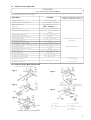
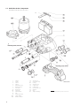
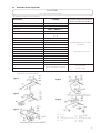
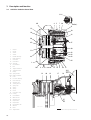
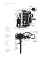
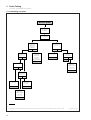
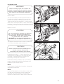
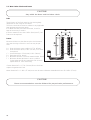
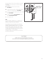
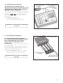
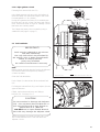
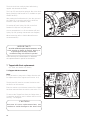
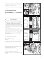
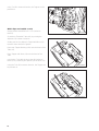
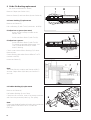
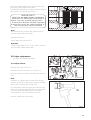
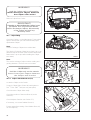
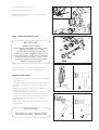
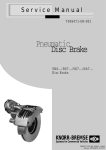
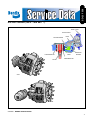
SD-23-7550
®
AIR DISC BRAKE (SB-6™ and SB-7™)
SUPPLY PORT
ACTUATOR ROD
RETURN SPRINGS
OUTER BRAKE PAD
ROTOR
LEVER
ACTUATING
BEAM
ECCENTRIC
BEARING
INNER BRAKE PAD
AXIAL
RADIAL
FIGURE 1 - BENDIX AIR DISC BRAKE
1
Index
Page
1
1.1
1.2
1.2.1
1.3
1.4
1.4.1
1.5
Exploded view of brake
Axial Disc Brake Components
Axial Disc Brake Repair Kits
Axial Disc Brake Wear Indicator Kits
Radial Disc Brake Components
Radial Disc Brake Repair Kits
Radial Disc Brake Wear Indicator Kits
Brake Disc Rotor
4
5
5
6
7
7
8
2
2.1
2.2
2.3
2.4
General information
(for “Axial- and Radial Disc Brake”)
Service Tools
Diagnostic Equipment
Lubrication
Torque requirements
9
9
9
9
3
3.1
3.2
3.2.1
3.2.2
3.2.3
3.3
3.4
3.4.1
3.4.2
3.4.3
Description and Function
Axial Disc Brake Sectioned View
Description of operation
Brake actuation
Brake release
Brake adjustment (automatic)
Radial Disc Brake Sectioned View
Description of operation
Brake actuation
Brake release
Brake adjustment (automatic)
10
11
11
11
11
12
13
13
13
13
4
Safety instructions for service work
(for “Axial- and Radial Disc Brake”)
5
Brake Testing
(for “Axial- and Radial Disc Brake”)
Troubleshooting procedure
Adjuster check
Wear limits of Brake Pads and Rotor
Brake wear check using Guide Pin (for Calipers with standard Guide Pins)
Brake wear check using Guide Pin (for Calipers with long Guide Pins)
Wear Indicators
Diagnostic-Equipment - Hand held device ZB9031
Diagnostic-Equipment - Vehicle mounted device ZB9033
14
15
16
18
19
20
21
21
Pad replacement
(for “Axial- and Radial Disc Brake”)
Pad removal
Tappet Boot check
Caliper floatation check
Pad fitting
22
22
23
23
Tappet with Boot replacement
(for “Axial- and Radial Disc Brake”)
Tappet with Boot removal
Adjuster thread inspection
Tappet with Boot fitting
24
25
25
5.1
5.2
5.3
5.3.1
5.3.2
5.3.3
5.4
5.5
6
6.1
6.1.1
6.1.2
6.2
7
7.1
7.1.1
7.2
8
2
Caliper Suspension Sealing
(for “Axial- and Radial Disc Brake”)
13
27
9
9.1
9.2
10
10.1
10.2
10.2.1
10.2.2
Guide Pin Bushing replacement
(for “Axial- and Radial Disc Brake”)
Brass Bushing replacement
Rubber Bushing replacement
28
28
28
Caliper replacement
(for “Axial- and Radial Disc Brake”)
Caliper removal
Caliper fitting
Caliper with Rubber Boot (10)
Caliper with Steel Cap (10a)
29
30
30
31
11
Carrier replacement
(for “Axial- and Radial Disc Brake”)
32
12
12.1
12.2
12.3
12.4
Actuation cylinder replacement
(for “Axial- and Radial Disc Brake”)
Brake Chamber removal
Brake Chamber fitting
Spring Brake removal
Spring Brake fitting
33
33
34
34
13
13.1
13.2
13.3
13.4
Additional Information
Service Video
Service Tool Kit
Diagnostic Equipment
General Safety Guidelines
35
35
35
36
Personal Notes
3
1 Exploded views
1.1 Axial Disc Brake Components
(for Wear Indicatators Kits see 1.2.1)
44
26
11 45
12
18/1
18/2
Assembly grease (coloured)
1
6*)
13
37
4
39
7
161
5
9
40
31
4
Caliper
Carrier
Sleeve
Sleeve
Rubber Bushing
Brass Bushing
Inner Boot
Outer Boot
Steel Cap
Pad Retainer
Pad
Tappet with Boot
Spring Brake
Assembly grease (white)
10
31a *)
)
10a *
1
2
4
5
6
7
9
10
10a
11
12
13
18/1
58
18/2
26
31
31a
37
39
40
44
45
58
161
Brake Chamber
Spring Clip
Outer Boot Clip
O-Ring
Adjuster Cap
Caliper Bolt
Caliper Bolt
Pad Retainer Pin
Washer
Ring
Tappet Bushing
2
VF 00127/12-ÄiO1
*) possible variants by items 10a & 31a
1.2
Axial Disc Brake Repair Kits
CAUTION
Use only Genuine Bendix® parts
The following Repair Kits are available
Description
Carrier Guide Kit
Carrier Guide Kit (Steel Cap)
Wear Indicator Kit
(per axle)
Guide Pins Kit
Guide Pins Kit (Steel Cap)
Seal Kit for Guide Pins
Tappet and Boot Kit (2 pcs)
Pad Set (per axle)
Adjuster Cap (4 pcs)
Pad Retainer Kit (per axle)
Pad Retainer Kit (per axle) wear sensor
Kit for Floating Pin
Outer Guide Seal Kit (10 pcs)
Kit for Fixed Pin
Kit for Steel Cap
Screw Kit for Steel Cap
Screw Kit for Outer Boot
Contents
Association of Repair Kits to the Disc
Brakes and Repair Kit’s Order no.
2, 4, 5, 31, 39, 40
2, 4, 5, 10a, 31a, 39, 40
for variants see 1.2.1
with or without 104
4-7, 9, 10, 31, 39, 40, 58
4, 5, 6, 7, 9, 10a, 31a, 39,
40, 58
9, 10, 31, 37, 58
13, 161
12, 26, 37, 44, 45
37
11, 26, 44, 45
11, 26, 44, 45, 104, 115, 116
4, 6, 39
10, 31
5, 7, 9, 10a, 31a, 40, 58
10a, 31a
10a, 31a, 39, 40
10, 31, 39, 40
Exchange Caliper r.h.
only in assembled condition
Exchange Caliper l.h.
see www.Bendix.com for more
information
http://www.Bendix.com
see Type plate
on the Caliper
1.2.1 Axial Disc Brake Wear Indicator Kits
(Typical kits are shown below)
Type 1
Type 4
Type 2
Type 5
Type 3
101
102
104
112
Sensor
115
Sensor
116
Cable Protection Plate 117
Clip
119
120
Spring Washer
Screw
Wear Indicator Cable
Bracket
Bracket
5
1.3 Radial Disc Brake Components
(for Wear Indicator Kits see 1.4.1)
1
2
4
5
6
7
9
10
10a
11
12
13
18/1
18/2
6
Caliper
Carrier
Sleeve
Sleeve
Rubber Bushing
Brass Bushing
Inner Boot
Outer Boot
Steel Cap
Pad Retainer
Pad
Tappet with Boot
Spring Brake
Brake Chamber
26
31
31a
37
39
40
44
45
58
161
Spring Clip
Outer Boot Clip
O-Ring
Adjuster Cap
Caliper Bolt
Caliper Bolt
Pad Retainer Pin
Washer
Ring
Tappet Bushing
*) possible variants by items 10a & 31a
1.4
Radial Disc Brake Repair Kits
CAUTION:
Use only Geniune Bendix parts
The following Repair Kits are available
Description
Carrier Guide Kit
Carrier Guide Kit (Steel Cap)
Wear Indicator Kit
(per axle)
Guide Pins Kit
Guide Pins Kit (Steel Cap)
Seal Kit for Guide Pins
Tappet and Boot Kit (2 pcs)
Pad Set (per axle)
Adjuster Cap (4 pcs)
Pad Retainer Kit (per axle)
Pad Retainer Kit (per axle) wear sensor
Kit for Rubber Sleeve
Outer Guide Seal Kit (10 pcs)
Repair Kit
Kit for Steel Cap
Screw Kit for Steel Cap
Screw Kit for Outer Boot
Contents
Association of Repair Kits to the Disc
Brakes and Repair Kit’s Order no.
2, 4, 5, 31, 39, 40
2, 4, 5, 10a, 31a, 39, 40
for variants see 1.2.1
with or without 104
4-7, 9, 10, 31, 39, 40, 58
4, 5, 6, 7, 9, 10a, 31a, 39,
40, 58
9, 10, 31, 37, 58
13, 161
12, 26, 37, 44, 45
37
11, 26, 44, 45
11, 26, 44, 45, 104, 115, 116
4, 6, 39
10, 31
5, 7, 9, 10a, 31a, 40, 58
10a, 31a
10a, 31a, 39, 40
10, 31, 39, 40
Exchange Caliper r.h.
only in assembled condition
Exchange Caliper l.h.
see www.Bendix.com for more
information
http://www.Bendix.com
see Type plate
on the Caliper
1.4.1 Radial Disc Brake Wear Indicator Kits
(Typical kits are shown below)
Type 1
Type 4
Type 2
Type 5
Type 3
101
102
104
112
Sensor
115
Sensor
116
Cable Protection Plate 117
Clip
119
120
Spring Washer
Screw
Wear Indicator Cable
Bracket
Bracket
7
1.5 Brake Rotors
(for “Axial- and Radial Disc Brake”)
When replacing the Rotors, please also refer to the instructions provided by the Vehicle Manufacturer.
They should also referred to when spec'ing Bendix Rotors.
When replacing Rotors, please adhere to the recommended bolt tightening torques.
The use of non-approved Brake Rotors will reduce levels of safety and invalidate warranty.
Brake Rotors can be ordered through any authorized Bendix parts outlet.
More information can be found on the internet at www.Bendix.com
This information booklet is also available electronically when you visit www.Bendix.com.
8
2
General Information
(for “Axial- and Radial Disc Brake”)
2.1 Service Tools
Part Number
Description
ll 19252
Press-In Tool for Tappet and Boot (13)
ll 19253
Pull-In Tool for Inner Boot (9)
ll 19254
II 32202
Pull-In/Out Tool for Brass Bushing (7)
Wedged Fork for removal of Tappet and Boot (13)
II 36797
Grooving Tool for Brass Bushing (7)
Z001105
Press in Tool for Steel Cap (10a)
Service tool kit ZB 9032 II 37951/004EX contains the
tools listed as well as this Service manual. The
service video is available separately
as Part No. KBP2060/1, in the UK, and elsewhere as
RA-SB0002 EN.
2.2 Diagnostic Equipment
Part Number
Description
ll 36695
ZB 9031 Hand held device for checking
Potentiometer function. ( Also Pad + Disc wear
when 13 pin chassis plug installed ).
ll 38691F
ZB 9033 Chassis mounted device for measuring
Pad + Disc wear
2.3 Lubrication
2)
Part Number
Description
Colour
Application
ll 14525
Renolit HLT2
White
2)
Brass Bushing (7)
II 32793
Syntheso GL EP1
Green
2)
Rubber Bushing (6)
Important Note: The correct Grease MUST be used for each Bushing!
2.4 Torque requirements
Item Number
39 + 40
Torque
Ft. lbs. [Nm]
Caliper Bolts
M16x1.5 - 10.9
Actuator Mounting Nuts
M16x1.5
210±18 [285
spanner size
in. (mm)
±25
132+22 [180
]
+30
]
0.55 (14)
0.94 (24)
9
3
3.1
Description and function
Axial Disc Brake Sectioned View
31a*)
161
9 5
7 40
10a*)
31
12
10
16
23
26
45
1
2
4
5
6
7
9
10
10a
11
12
13
16
17
18/1
18/2
19
20
22
23
24
26
27
28
30
31
31a
32
33
37
39
40
44
45
46
161
10
Caliper
Carrier
Sleeve
Sleeve
Rubber Bushing
Brass Bushing
Inner Boot
Outer Boot
Steelcap
Pad Retainer
Pad
Tappet with Boot
Threaded Tube
Bridge
Spring Brake
Brake Chamber
Lever
Eccentric Bearing
Inner Seal Cap
Adjuster Unit
Turning Device
Spring Clip
Spring
Spring
Chain
Outer Boot Clip
O-Ring
Chain Wheel
Wear Sensor
Adjuster Cap
Caliper Bolt
Caliper Bolt
Pad Retainer Pin
Washer
Rotor
Tappet Bush
37
30
11
32
33
43
44
24
1
161
2
13 22 4
39
6
18/1
18/2
12
46
12
17
19
27
28
20
VF 00127/2-Äi01
*) possible variants by items 10a & 31a
3.2 Description of operation
(Floating Caliper principle)
3.2.1 Brake actuation
During actuation, the Push Rod of the Actuator (18/1
or 18/2) moves the Lever (19). The input forces are
transferred via the Eccentric Bearing (20) to the
Bridge (17). The force is then distributed by the
Bridge (17) and the two Threaded Tubes (16) to the
Tappets (13) and finally to the inboard Pad (12).
After overcoming the running clearance between the
Pads and the Rotor, the reaction forces are transmitted to the outboard Pad (12). The clamping forces on
the Pads (12) and the Rotor (46) generate the braking
force for the wheel.
3.2.2. Brake release
After releasing the air pressure, the two Return
Springs (27/28) push the Bridge (17) and Lever (19)
back to the start position; this ensures a running
clearance between Pads and Disc is maintained.
3.2.3 Brake adjustment (automatic)
To ensure a constant running clearance between
Disc and Pads, the brake is equipped with a low
wearing, automatic adjuster mechanism.
The Adjuster (23) operates with every cycle of actuation due to the mechanical connection with Lever
(19). As the Pads and Disc wear, the running clearance increases. The Adjuster (23) and Turning
Device (24) turn the Threaded Tubes (16) by an amount necessary to compensate for this wear. The total
running clearance (sum of clearance both sides of
Disc) should be between 0.03 and 0.04 in. (0.6 and
0.9 mm.; smaller clearances may lead to overheating
problems.
11
3.3
Radial Disc Brake Sectioned View
31a*)
9
10
31
7
5
40
161
10a*)
16
24
22
33
44
32
26
45
11
30
17
37
1
2
4
5
6
7
9
10
10a
11
12
13
16
17
18/1
18/2
19
20
22
23
24
26
27
28
30
31
31a
32
33
37
39
40
44
45
46
161
12
Caliper
Carrier
Sleeve
Sleeve
Rubber Bushing
Brass Bushing
Inner Boot
Outer Boot
Steelcap
Pad Retainer
Pad
Tappet with Boot
Threaded Tube
Bridge
Spring Brake
Brake Chamber
Lever
Eccentric Bearing
Inner Seal Cap
Adjuster Unit
Turning Device
Spring Clip
Spring
Spring
Chain
Outer Boot Clip
O-Ring
Chain Wheel
Wear Sensor
Adjuster Cap
Caliper Bolt
Caliper Bolt
Pad Retainer Pin
Washer
Rotor
Tappet Bushing
43
23
1
VF 00113/3-Äi01
13 39 4 6
2
12
27; 28 20
19
18/1; 18/2
46
VF 00113/4
*) possible variants by items 10a & 31a
3.4 Description of operation
(Floating Caliper principle)
4 Safety Instructions for service work
3.4.1.
Please refer to the relevant safety instructions for
repair work on commercial vehicles, especially for
jacking up and securing the vehicle.
Brake Actuation
During actuation, the Push Rod of the Actuator (18/1
or 18/2) moves the Lever (19). The input forces are
transferred via the Eccentric Bearing (20) to the
Bridge (17). The force is then distributed by the
Bridge (17) and the two Threaded Tubes (16) to the
Tappets (13) and finally to the inboard Pad (12).
After overcoming the running clearance between the
Pads and Rotor, the reaction forces are transmitted to
the outboard Pad (12). The clamping forces on the
Pads (12) and the Rotor (46) generate the braking
force for the wheel.
3.4.2. Brake release
After releasing the air pressure, the two Return
Springs (27/28) push the Bridge (17) and Lever (19)
back to the start position; this ensures a running
clearance between Pads and Rotor is maintained.
3.4.3
Brake adjustment (automatic)
To ensure a constant running clearance between
Rotor and Pads, the brake is equipped with a low
wearing, automatic adjuster mechanism. The
Adjuster (23) operates with every cycle of actuation
due to the mechanical connection with Lever (19). As
the Pads and Rotor wear, the running clearance
increases. The Adjuster (23) and Turning Device (24)
turn the Threaded Tubes (16) by an amount necessary to compensate for this wear. The total running
clearance (sum of clearance both sides of Rotor)
should be between 0.03 and 0.04 in. (0.6 and
0.9 mm.; smaller clearances may lead to overheating
problems.
(for “Axial- and Radial Disc Brake”)
Use only Genuine Bendix parts.
WARNING!
Before starting repair work, block the
wheels to ensure that the vehicle cannot
roll away, before releasing the park brake.
See Page 36 for full Safety Guidelines.
Please follow repair manual instructions and adhere
to the wear limits of the Pads and the Rotors - see
Section 5.3.
Use only recommended tools - see Section 2.1.
Tighten bolts and nuts to the recommended torque
values - see Section 2.4.
After re-fitting the wheel according to the Vehicle
Manufacturer’s recommendations, please ensure that
there is sufficient clearance between the Tire Valve
Stem, the Caliper and the wheel rim, to avoid damage to the Valve.
After service work:
Check the brake performance and the system behavior by actual road test.
13
5
Brake Testing
(for Axial- and Radial Disc Brake)
5.1 Fault finding procedure
Air Disc Brake
Lift vehicle,
turn wheel
by hand
Does wheel
turn smoothly?
NO
Residual
pressure
within the
braking
cylinder?
NO
Running
clearance ok?
(see section 5.2)
NO
YES
YES
Running
clearance ok?
(see section 5.2)
Yes
NO
Check and if
necessary,
change or
service
preceding
braking device
Check adjuster
(see section 5.2)
YES
Brake pad wear
uneven?
(see note below)
END
NO
END
YES
END
Check and if
necessary,
maintain caliper
guide pins
Adjuster ok?
NO
YES
(see section 9)
END
Caliper
guidance ok?
(see section 6.1.2)
NO
Change caliper
YES
(see section 10)
Tightness not
due to disc
brake
END
END
Check and if
necessary,
maintain caliper
guide pins
(see section 9)
END
Note: Difference between inboard and outboard pad less than 0.2in.(< 5mm), and diagonal wear ≤ 0.08in (2 mm)
14
FD00102EN-Äi01
5.2 Adjuster check
WARNING!
Before starting repair work, block the
wheels to ensure that the vehicle cannot
roll away, before releasing the park brake.
See Page 36 for full Safety Guidelines.
23 37
Remove wheel.
The caliper assemply should be pushed inboard on
its guide pins. Using a suitable tool, press the inboard pad (12) away from the Tappets and check
Tappet and inboard pad backplate - it should be between 0.02in. (0.5mm) & 0.04in. (1.0mm). If the running
clearance is too small or large, the adjuster may not be
functioning correctly and should be checked as follows.
M+P-KN-039
Remove Cap (37).
23
CAUTION!
Do not overload or damage the Adjuster
(23). Use only 8mm Box End Wrench
or 1/4Ó" drive Socket with a lever length
no greater than 4in. (100mm).
DO NOT use an Open Ended Wench
since this may damage the Adjuster shaft.
37
1
M+P-KN-015
The Adjuster should be turned counter-clockwise for
2 or 3 clicks (increasing running clearance).
CAUTION!
Make sure that the Box End Wrench or
Socket can turn freely while
completing the following procedures.
By applying the brake 5 - 10 times (about 30psi, or
2 Bar) the Box End Wrench or Socket should turn
clockwise in small increments if the Adjuster is
functioning correctly (see notes below).
M+P-KN-043
If Pads are not being changed, Cap (37) should be
replaced having lightly greased it with Renolit HLT2
(available as part number II14525).
NOTE:
As the number of applications increases, incremental
adjustment will decrease.
NOTE:
If the Box End Wrench or Socket does not turn, turns
only with the first application or turns forward and
backward with every application, the automatic
Adjuster has failed and the Caliper must be replaced.
15
5.3 Wear Limits of Pads and Rotors
CAUTION!
Stay within the Rotor and Pad Wear Limits
Pads
The thickness of the Pads must be checked regularly
dependent on the usage of the vehicle.
The Pads should be checked to adhere to any applicable
legal requirements that may apply.
If no Wear Indicator has been connected, check for
wear at least every 3 months.
If friction material is less than 0.08in. (2mm) (see E), the
Pads must be replaced.
C
A
B
Rotors
Measure thickness at the thinnest point. Avoid measuring near the edge of the disc as a burr may be present.
A = Rotor thickness (new condition) 1.77in. (45mm)
B = Rotor thickness (worn) 1.46in. (37 mm), Disc must
be replaced
C = Overall thickness of Pad (new) 1.18in. (30mm)
D = Backplate 0.35in. (9mm)
E = Minimum thickness of friction material 0.08in. (2mm)
F = Minimum allowed thickness in worn condition
for backplate and friction material 0.43in. (11mm)
(replacement of Pads necessary).
E
D
F
M+P-KN-002
If wear dimension B ≤ 1.53in. (39 mm) Rotor should be
replaced together with Pads.
Wear dimension B = 1.46in. (37 mm) must not decrease. Minimum allowable thickness B=1.46in. (37 mm)
CAUTION!
These recommendations must be followed for proper brake performance.
16
A1
a
At each change of Pads check the Rotors for grooves
and cracks.
The diagram at the right shows possible conditions
of the surface.
A1 = Small cracks spread over the surface
are allowed
B1
max. 0.75 x a
max. 1.5 mm
B1 = Cracks less than 0.06in. (1.5mm) deep or wide,
running in a Radial direction, are allowed
C1 = Grooves (circumferencial) less than 0.06in. (1.5mm)
wide are allowed
D1
C1
D1 = Cracks in the vanes are not allowed and the
Rotor MUST BE REPLACED.
a = Pad contact area
Note
In case of surface conditions A1,-C1, the Rotor can
remain in service until it has reached the minimum
thickness of 1.46in. (37 mm) is reached.
VF 00127/3
Knorr-Bremse Rotor are normally service-free and
refinishing, when changing Rotors, is not necessary.
However, refinishing could be useful, e.g. to increase
the load-bearing surface of the Pads, after severe
grooving on the entire friction surface has occurred.
To meet safety requirements, the minimum thickness
after refinishing is > 1.53in. (39 mm).
In addition, follow the recommendations provided by
the Vehicle Manufacturer.
CAUTION!
Follow these recommendations. Excessive
Pad or Disc wear will degrade optimum performance.
17
5.3.1 Brake Wear Check using Guide Pin (For all Axial and Radial Disc Brakes except those listed in
Section 5.3.2 - These Callipers do not have the rib in position B (see also Section 5.3.2)
1
4
1
4
6
6
C
B
D
M+P-KN-005
Pad conditions can be visually inspected without
removing the road wheel by noting the positon
of the Floating Pin (4) in the Caliper (1).
If dimension ‘C’ is less than 0.04in. (1mm), a more
accurate check of the Pads and Disc must be
completed.
If necessary change the Pads - see Section 6
18
B = without rib (see also Section 5.3.2)
C = pin protrusion - shown in new condition
D = minimal pin protrusion - Pads and Rotor must be
checked with road wheel removed
5.3.2 Brake Wear Check using Guide Pin (Only for Axial Disc Brakes SB 7541, SB 7551 to SB 7629,
SB 7639 and Radial Disc Brakes SB 7102, SB 7112, SB 7103, SB 7113, SB 7104, SB 7114,
SB 7105, SB 7115, SB 7108, SB7118, SB 7109, SB 7119, SB 7120, SB 7130 - These Callipers do
have the rib in position B (see also Section 5.3.1)
1
1
4
6
4
6
B
C
D
Pad conditions can be visually inspected without
removing the road wheel by noting the positon
of the Floating Pin (4) in the Caliper (1).
M+P-KN-006
B = with rib (see also Section 5.3.1)
C = new condition
D = 0.64in. (18mm) or more, Pads and Rotor must be
checked with road wheel removed
If the head of the Floating Pin (4) is inside the
Rubber Bush (6) by a dimension D greater than
0.64in. (18mm), then a more accurate check of the
Pads and Rotor must be made.
If necessary, change the Pads - see Section 6.
19
5.3.3 Wear Indicators
There are two types of Pad Wear Indicators available
to accommodate the differences in vehicle types and
manufacturers, including:
a)
b)
In - Pad Normally Closed Indicator - Circuit is
broken when Pad Wear reaches the limit.
In - Pad Normally Open Indicator - Circuit is
made when Pad Wear reaches the limit.
See Figure to the right.
M+P-KN-007
c)
Wear Indicator using built in Potentiometer. This
is available either as an on/off version or
as a continuous signal version which can be
linked to the vehicle’s electronic monitoring
systems.
An optical or acoustic device may be linked to any of
the above.
Important
Please refer to the specifications provided by the
Vehicle Manufacturer
M+P-KN-008
20
5.4 Bendix Diagnostic Equipment
The Bendix Diagnostic Unit ZB 9031 is a
hand held device suitable for vehicles that are fitted
with Bendix Air Disc Brakes using a continuous
signal type of Wear Potentiometer.
The wear condition of each brake can be measured
by connecting the device to a suitable 13 pin socket
(DIN 72570) where fitted. This socket must have
been connected to each sensor by the vehicle
manufacturer.
The Diagnostic unit permits:
Quick and simple wear check.
A check of the potentiometer function.
A detailed instruction manual is included with
each unit.
5.5 Bendix Diagnostic Equipment
The Bendix Wear Check Module ZB 9033
is a chassis mounted device suitable for vehicles
that are fitted with Bendix Air Disc Brakes
using a continuous signal type of Wear
Potentiometer.
The module continuously monitors and displays the
wear at each brake.
For vehicles without an automatic brake control
system, particularly Trailer applications, the module
enables a quick and simple wear check.
The Wear Check Module permits:
Up to six (6) Brakes to be checked together.
LED monitoring of each Brake condition.
A detailed instruction manual is included with
each unit.
21
6 Pad replacement
(for “Axial- and Radial Disc Brake”)
WARNING!
Before starting repair work, block the
wheels to ensure that the vehicle cannot
roll away, before releasing the park brake.
See Page 36 for full Safety Guidelines.
6.1 Pad removal
Take the wheel off (refer to Vehicle Manufacturer’s
recommendations).
Remove Clip (26) and Washer (45), push down the
Pad Retainer (11) and remove Pin (44).
If the Pad Retainer (11) is corroded, it should be
replaced.
44
11
Important
Before removing the Pads, it is strongly recommended
that the Adjuster mechanism should be checked for
correct operation. See Section (5.2)
45
26
M+P-KN-010
CAUTION!
Do not overload or damage the Adjuster
(23). Use only 8mm Box End Wrench
or 1/4” drive Socket with a lever length
no greater than 4in. (100mm).
DO NOT use an Open Ended Wrench
since this may damage the Adjuster shaft.
23
Remove Cap (37).
37
Turn the Adjuster counter-clockwise until the Pads can
be removed. A clicking noise will be heard during
this procedure.
Push inboard Pad (12) toward Actuator.
12
Pull out both Pads (12).
12
M+P-KN-011
6.1.1 Tappet Boot Check
The Adjuster (23) should be screwed clockwise until
the boots are clearly visible.
The Boots should not show any damage.
Check the attachment of the Boots into the Caliper
housing.
13
Important
Any ingress of water or dirt past the Tappet Boot will
lead to corrosion and affect the function of the
Actuation Mechanism and Adjuster Unit.
If damaged, the Boot and Tappet must be replaced
(see Section 7).
22
M+P-KN-012
6.1.2 Caliper guidance check
31a*)
Following Pad removal (Section 6.1)
Using hand pressure only (no tools), the Caliper (1)
must slide freely over the whole length of the Guide
Pin arrangement > 1.2in. (30mm).
During this operation the Sleeve (5) is sealed by the
Boot (9) and Cap (10) or Steel Cap (10a) and O-Ring
(31a). These must show no signs of damage. Check
that these are correctly seated.
10a*)
9 5 7
10
The Caliper may have to be re-sealed by using a
suitable Kit (see page 5 or page 7).
6.2 Pad installation
IMPORTANT!
Pads must be changed as an axle set
and NOT individually.
Use only Pads which are permitted by
the vehicle, axle, or brake manufacturer.
Failure to comply with this
policy may invalidate
the vehicle manufacturer’s warranty.
Note:
Before placing the Pads into the Carrier, the Adjuster
(23) must be further de-adjusted by rotating it
counter clockwise.
1
4
M+P-KN-013-Äi01
6
*) possible variants by items 10a & 31a
Clean the Pad abutments.
Push Caliper (1) outboard and fit the outboard Pad
(12).
1
For fitting the inboard Pad (12), push Caliper (1) in the
opposite direction.
If fitted, replace Wear Indicators and fittings /
brackets, etc. See page 5 or 7.
CAUTION!
Do not overload or damage the Adjuster
(23). Use only 8mm Box End Wrench or
1/4" drive Socket with a lever length no
greater than 4 in. (100mm).
DO NOT use an Open Ended Wrench
since this may damage the Adjuster shaft.
12
M+P-KN-014
Rotate the Adjuster clockwise until the Pads come
into contact with the Rotor. Then turn back the
Adjuster 2 clicks.
23
The hub should turn easily by hand after having
applied and released the brake.
The Cap (37) must then be replaced after it has been
lightly greased it with Renolit HLT2 (available as part
number II14525).
After setting the Pad Retainer (11) into the groove of
the Caliper (1), it must be pushed in to allow the
insertion of the Pad Retainer Pin (44).
44
Fit washer (45) and Spring Clip (26) to the Pad
Retainer Pin (44) (use only new parts).
11
Our recommendation is to fit the Washer (45) and
Spring Clip (26) pointing downwards (see diagram).
1
45
26
Wheel mounting (refer to Vehicle Manufacturer’s
recommentations).
M+P-KN-016
IMPORTANT!
As with all brake pad replacements, new
Pads require a break-in period. Heavy or
or prolonged braking should be
avoided during this break-in period.
Follow Industry recommendations to determine
the optimum break-in period for the vehicle.
7 Tappet with Boot replacement
(for “Axial- and Radial Disc Brake”)
7.1 Tappet with Boot removal
Note:
It may be easier to remove the Caliper from the axle
for replacement of the Tappets (see Section 10.1).
13
The Adjuster (23) must be screwed clockwise until
the Boots can be reached.
Exercise caution to avoid thread overrun if the Caliper
has been removed from the vehicle (see setion 7.1.1.).
To remove the Tappet Boot from the Caliper bore, a
Screwdriver should be used to deform the Boot location ring - see diagram.
CAUTION!
Because it is not a replacement item, use
caution to avoid damage to the Inner Seal.
24
13
M+P-KN-017
The Tappets (13) can be removed from the Threaded
Tubes by using Wedge Fork A. (Order No. II32202).
Remove the old Tappet Bush (116).
A
Check Inner Seal (arrow) and if damaged, replace the
Caliper.
13
A 13
7.1.1 Adjuster thread inspection
Place an new thickness Pad (12) into the outboard
gap to avoid overrunning of the Threaded Tubes.
161
VF 00127/4
IMPORTANT!
12
Threaded Tubes should not be extended
beyond thread engagement of the Bridge.
If thread engagement (synchronization) is
lost, the Caliper must be replaced.
16
For the inspection of the threads, the tubes must be
screwed out (max. 1.2in. [30mm]) by turning the Adjuster
(23) clockwise.
46
M+P-KN-019
If Caliper is not installed on axle, put a spacer E
(length = 2.76in. [70mm]) into the Caliper (1) to avoid
overrunning of the Threaded Tubes (16) when adjusting
them out (see illustration opposite). During adjusting,
the threads can be checked for corrision damage.
In case of water ingress or corrosion, the Caliper
must be replaced.
70 mm
E
16
7.2 Tappet with Boot installation
With Caliper fixed to axle:
Grease threads with RENOLIT HLT2 (Order No.
II14525).
1
VF 00127/13
Screw back Threaded Tubes (16), by turning the
Adjuster (23) counter-clockwise.
Place new Tappet Bushing (161) onto the head of the
Tube (16).
Sealing seat in the Caliper for Tappet with Boot (13)
must be clean and free of grease.
B
161
13
Place Tappet with Boot (13) onto the head of the
Tube.
Use Push-In Tool with the short strut (B)
(Order No II19252) for positioning and pressing-in the
Boot (13).
VF 00127/5
25
Using Tool B in reverse direction, the Tappet can be
pressed on.
B
13
With Caliper not installed on axle
Grease threads with RENOLIT HLT2 (Order No.
II14525).
M+P-KN-022
Screw back Threaded Tubes (16), by turning the
Adjuster (23) counter-clockwise.
Sealing seat in the caliper for Tappet with Boot (13)
must be clean and free of grease.
B
13
Place new Tappet Bushing (161) onto the head of the
Tube (16).
Place Tappet with Boot (13) onto the head of the
Tube.
Use Push-In Tool with the long strut (B) (Order No
II19252) for positioning and pressing-in the Boot (13).
Using the Tool (B) in reverse direction, the Tappet can
be pressed on.
M+P-KN-021
13
B
M+P-KN-023
26
8 Caliper Suspension sealing
(Replacement of inner Boot (9) )
(for the Axial and Radial Disc Brake)
Remove Caliper (see Section 10.1)
Remove Ring (58)
Pull out Sleeve (5)
5
Push out Boot (9) with screw driver.
9
Inspect and clean contact area of Boot (9)
Put new Boot (9) into the Cup (arrow) of the Tool C
(Order No II19253).
58
M+P-KN-025
9
9
C
Position Sleeve with Boot (9) into the Caliper bore
and pull in.
M+P-KN-026
Fit the Sleeve (5)
The Boot end must engage in the groove of the
Sleeve (5) (arrow). Lock with Ring (58) by pushing
on until it engages.
Important:
Before fitting the Caliper, the unsealed Sleeve with the
Rubber Bushing should be checked for its ability to
slide.
58
5
9
VF 00127/15
Fit Caliper (see Section 10.2).
27
9 Guide Pin Bushing replacement
(for “Axial- and Radial Disc Brake”)
7
D
Remove Caliper (see Section 10.1)
Remove Sleeve (5) and inner Boot (9) (see Section 8).
9.1 Brass Bushing (7) replacement
Remove old Sleeve (5).
Pull out Bushing (7) with Tool (D) (Order No. II19254).
VF 00127/16
If Caliper has no groove (see arrow)
(Note: Groove is always located on the
inboard side)
D
Pull in new Brass Bush (7) with Tool (D).
If Caliper has a groove:
Pull in new Brass Bush (7) with Tool (D).
To prevent longitudinal displacement, use
Tool (F) (Order No II36797) to create
dents in bushing.
Check contact area of Brass Bushing (7) for burrs.
Remove burrs.
Grease Bushing with white Grease RENOLIT HLT2
(Order No II14525).
7
VF 00127/17
Insert new Sleeve (5).
Note:
The Guide Pins Kit contains new Sleeves (4) & (5)
and new Caliper Bolts (39) & (40) (see Section 1.2
and 1.4).
9.2 Rubber Bushing (6) replacement
Remove old Sleeve (4)
Pull Rubber Bushing (6) out of bore.
Check bore for corrosion, clean, if necessary coat bore
with Corrosion protection paint (e.g. Zinc spray).
Note:
Grease new Rubber Bushing (6) inside and outside with
green Grease SYNTHESO GL EP 1 (Order No
II32793).
6
4
M+P-KN-030
28
Deform new Rubber Bushing (6) and push from the
inner side of the Caliper into the bore.
Push Rubber Bushing (6) so that the outer positioning
ring locates in the groove (see arrows).
6
IMPORTANT!
Never use the white Grease (containing
mineral oil) for lubricating the Bushing or
Sleeve. Use only synthetic based green
Grease (Part Number II32793). Improper
Grease may cause the rubber Bushing to
swell and prevent proper floatation.
M+P–KN–031
Note:
The Guide Pins Kit contains new Sleeves (4) & (5)
and new Caliper Bolts (39) & (40).
Assemble Sleeve (4)
Re-fit Caliper (see Section 10.2)
Important:
+25
+18
Torque Caliper Bolts to 210 ft. lbs. (285 Nm) and
check that the Caliper slides easily.
10 Caliper replacement
(for Axial- and Radial Disc Brake)
10
10.1 Caliper removal
39
Remove Pads (see Section 6.1)
31
31
10a
31a
Remove Actuator (see Section 12.1 and 12.3).
40
Remove Outer Boot Clip (31) and take off Outer Boot
(10)
Note:
In addition to Calipers with an Outer Boot (10) and
Outer Boot Clip (31), there are also versions available
with a Steel Cap (10a) and O-Ring (31a).
10
M+P-KN-024-Äi01
On models with Steel Caps (10a) and O-Rings (31a),
place tool (G) (Part Number Z001105) onto the Steel
Cap and tighten the threated pin by a hexagon
socket spanner. Then use hammer as shown.
Remove Caliper Bolts (39 and 40).
29
WARNING!
Hold the Caliper only on the exterior.
Never insert your fingers between
the Caliper and Carrier!
Remove Caliper from Carrier.
IMPORTANT!
Opening or dismantling the Caliper is not
permitted. Use only Genuine Bendix
service Exchange Calipers. Disassembly
of the Caliper will void any
Warranty Claim.
FD00114
10.2 Caliper fitting
Check the Part No. on the label (arrow, Figure above
right) to ensure that you have selected the proper
replacement Caliper.
Note:
Service Exchange Calipers have a blue label.
The Service Exchange Caliper has a plastic cap or an
adhesive tape in the area of the Actuator attachment.
Remove the cap or tape after installing the Caliper
(see arrow).
FD00116
Note:
The service exchange Caliper includes sealing and
guiding elements. The Pads are not included.
WARNING!
39
Hold the Caliper only on the exterior.
Never insert your fingers between
the Caliper and Carrier!
31
10.2.1 Caliper with Rubber Boot (10)
10a
31a
40
10
Locate the Caliper to the Carrier.
FD00113
Screw-in Caliper Bolts (39 and 40) and tighten to
+18
+25
210 ft. lbs. (285 Nm) (use only new parts).
Check that the Caliper slides easily.
Check the position of the Inner Boot (9) on the
Sleeve (5).
9
Check Adjuster function (see Section 5.2)
If necessary, use a new Rubber Boot (10).
Ensure grease-free seating of the Rubber Boot (10)
on the Caliper (1)
30
58
5
M+P-KN-027
Tighten Rubber Boot Clip (31)
Fit the Pads (see Section 6.2)
Attach the Brake Chamber or Spring Brake (see
Section 12.2 or 12.4)
39
31
31
M+P-KN-042
10.2.2 Caliper with Steelcap (10a)
10
IMPORTANT!
Replace the Rubber
Boot (10) by the Steel Cap (10a) when
replacing the Sleeve (5), the
O-Ring (31a) and the Screw (40)
at the same time. Replace only on the
recommendation of the Axle or Vehicle
manufacturer. On SB 6... (19.5“) only
permissible after manufacturing date
A0026. (see type plate).
5
31
40
31a
10a
FD00108
It may be easier to remove the Caliper and the
Carrier from the axle to replace the Steel Cap.
Assembly at the Vehicle :
The fitting must be carried out with the Pads installed.
- Clean the area.
- Using the Grease supplied (II14525), lightly lubricate
the O-Ring and place it over the cast spigot (see
Sketch).
- Remove the Threated Pins from the assembly tool (G)
to avoid damaging the Steel Cap.
- Hold the new Steel Cap on the end of the Spigot.
By using a suitable press or special assembly tool
(Part Number Z001105) and a hammer, press the
Steel Cap fully on the spigot making sure not to
deform the Cap.
After removal, the Steel Cap and the O-Ring must
not be refitted.
2mm
FD00106
X
IMPORTANT!
The Steel Cap (10a) and the O-Ring
are single use items - do not re-use.
X
V
31
Assemply on the Caliper and Carrier removed
from the axle:
IMPORTANT!
Replace the Rubber
Boot (10) by the Steel Cap (10a) when
replacing the Sleeve (5), the
O-Ring (31a) and the Screw (40)
at the same time. Replace only on the
recommendation of the Axle or Vehicle
manufacturer. On SB 6... (19.5“) only
permissible after manufacturing date
A0026. (see type plate).
Put the Caliper on the Carrier.
IMPORTANT!
9
Special threaded Screw (40) and Steel
Cap (10a) as well as the O-Ring (31a)
must be renewed whenever Screw (40)
has been removed.
Screw-in Caliper Bolts (39 and 40) and tighten to
+25
+18
210 ft. lbs. (285 Nm).
Check the position of the Inner Boot (9) on the
Sleeve (5).
5
FD00112
Clamping device
9
Check that the Caliper slides easily.
In the exposed clamping (e.g. vice), press the Caliper
against the Carrier as far as possible. The Inner Boot
(9) must be in compressed condition to prevent
air being trapped inside of the Cap.
Direction
of pressure
Assembly of the Steel Cap (10a) can now be
carried out as in Section “ Assembly at the Vehicle“.
Check Adjuster (Section 5.2).
FD00110EN
11 Carrier replacement
(for Axial- and Radial Disc Brake)
Remove Caliper (see Section 10.1).
Remove Carrier (2) from axle.
Clean axle contact area.
2
Bolts are not supplied by Bendix. Attach the new
Carrier with new bolts from the truck manufacturer.
Attach the Caliper (see Section 10.2)
32
M+P-KN-036
12 Actuation cylinder replacement
(for “Axial- and Radial Disc Brake”)
12.1 Brake Chamber removal
Disconnect the air line from the Brake Chamber (18/2)
Unscrew the Brake Chamber Mounting Nuts (do not
re-use them).
18/2
Remove the Brake Chamber
VF 00127/10
12.2 Brake Chamber fitting
IMPORTANT:
New Brake Chambers (18/2) have drain plugs installed. Remove the bottom plug (see arrows). All other drain
holes should be plugged.
Before fitting the new Brake Actuator, the sealing
surface of the Caliper (see arrow) must be cleaned, and
the Spherical Cup (19) in the Lever must be greased
with white Grease RENOLIT HLT2 (Order no II14525).
The surface area of the flange must be clean.
IMPORTANT!
Do not use Grease containing molybdenum disulphate. Use only Bendix
Actuators recommended
by the Vehicle Manufacturer.
19
M+P-KN-034-Äi01
Attach Actuator with new Nuts
(self-locking EN ISO 7042) and torque tighten
+30
+22
to 133 ft. lbs. (180 Nm).
Connect the air hose and check for leakage.
Make sure that the hose is not twisted and that chafing
is not possible.
IMPORTANT!
Road test vehicle before returning to service.
Test any air hoses or fittings removed
during maintenance work, using a soap
solution to check for leakage. A 1 inch
bubble in 1 minute is acceptable, otherwise
repair/replace components as necessary.
33
12.3 Spring Brake removal
WARNING!
Before starting repair work, block the
wheels to ensure that the vehicle cannot
roll away, before releasing the park brake.
18/1
See Page 36 for full Safety Guidelines.
Release the parking brake, move the Hand Control
Valve to the ‘run’ position.
Screw-out Release Bolt (arrow) with a maximum torque of 26 ft. lbs. (35Nm).
VF 00127/11
Release air from brake, move Hand Control Valve to
‘park’ position.
Mark the hoses to assist with re-connection, then
disconnect them from the Spring Brake Actuator (18/1).
Unscrew the Spring Brake Actuator Mounting Nuts (do
not re-use).
Remove the Spring Brake Actuator.
12.4 Spring Brake Installation
IMPORTANT!
New Spring Brake Actuators (18/1) have drain plugs
installed. Remove the bottom plug (see arrows).
All other drain holes should be plugged.
Before fitting the new Brake Actuator, the sealing
surfaces of the Caliper have to be cleaned, and the
Spherical Cup (19) in the Lever must be greased with
white Grease RENOLIT HLT2 (Order no II14525)
The surface area of the flange must be clean.
19
M+P-KN-034-Äi01
IMPORTANT!
Do not use grease containing
molybdenum disulphate.
Use only Bendix Actuators
recommended by the
Vehicle Manufacturer.
IMPORTANT!
On Radial Disc Brakes the Drain Plugs in
the bottom of the Cylinder Flange must
be open.
34
FD00115
Attach the Actuator with new Nuts
(self-locking EN ISO 7042) and torque tighten to
+30
+22
133 ft.lbs. (180 Nm).
Connect air hose, ensuring that hoses are correctly
connected.
Make sure that hoses are not twisted and that chafing is not possible.
Push park control valve in to release parking brake,
and check for leakage.
Screw in Spring Brake Release bolt to maximum
52 ft.lbs. (70 Nm).
IMPORTANT!
Road test vehicle before returning to service. Test any air hoses or fittings reinstalled
during maintenance work, using a soap solution to check for leakage. A 1 inch
bubble in 1 minute is acceptable, otherwise repair/replace components as necessary.
13 Additional information
13.1 Service Video
A Video is available for additional
information.
Order number: RA-SB0002.EN Video (English)
RA-SB0002.FR Video (French)
RA-SB0002.PO Video (Portugese)
RA-SB0002.SP Video (Spanish)
13.2 Service Tool Kit ZB 9032
For service and repair work we recommend
our BendixTool Kit ZB 9032 II 37951/004EX,
which contains all the necessary special tools.
13.3 Diagnostic Equipment
For vehicles fitted with continuous
potentiometer type wear sensors,
Bendix Diagnostic Equipment may
be used to ensure quick and simple
measurement of wear at each caliper.
See sections 5.4 and 5.5.
35
13.4 General Safety Guidelines.
WARNING! Please READ and follow these
instructions to avoid personal injury or death:
When working on or around a vehicle, the
following general precautions should be
observed at all times.
1. Park the vehicle on a level surface, apply the
parking brakes, and always block the wheels. Always
wear safety glasses.
2. Stop the engine and remove ignition key when
working under or around the vehicle. When working in
the engine compartment, the engine should be shut
off and the ignition key should be removed. Where
circumstances require that the engine be in operation,
EXTREME CAUTION should be used to prevent
personal injury resulting from contact with moving,
rotating, leaking, heated or electrically charged
components.
3. Do not attempt to install, remove, disassemble or
assemble a component until you have read and
thoroughly understand the recommended procedures.
Use only the proper tools and observe all precautions
pertaining to use of those tools.
4. If the work is being performed on the vehicle’s air
brake system, or any auxiliary pressurized air
systems, make certain to drain the air pressure from
all reservoirs before beginning ANY work on the
vehicle. If the vehicle is equipped with an AD-IS™ air
dryer system or a dryer reservoir module, be sure to
drain the purge reservoir.
5. Following the vehicle manufacturer’s
recommended procedures, deactivate the electrical
system in a manner that safely removes all electrical
power from the vehicle.
6. Never exceed manufacturer’s recommended
pressures.
7. Never connect or disconnect a hose or line
containing pressure; it may whip. Never remove a
component or plug unless you are certain all system
pressure has been depleted.
8. Use only genuine Bendix® replacement parts,
components and kits. Replacement hardware, tubing,
hose, fittings, etc. must be of equivalent size, type
and strength as original equipment and be designed
specifically for such applications and systems.
9. Components with stripped threads or damaged
parts should be replaced rather than repaired. Do not
attempt repairs requiring machining or welding unless
specifically stated and approved by the vehicle and
component manufacturer.
10. Prior to returning the vehicle to service, make
certain all components and systems are restored to
their proper operating condition.
11. For vehicles with Antilock Traction Control (ATC),
the ATC function must be disabled (ATC indicator
lamp should be ON) prior to performing any vehicle
maintenance where one or more wheels on a drive
axle are lifted off the ground and moving.
For more information
visit:
www.Bendix.com
36
BW2000 ©2002 Bendix Commercial Vehicle Systems LLC. All rights reserved. Printed in USA.