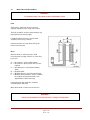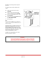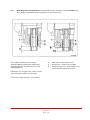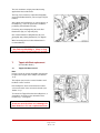
1
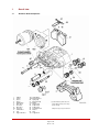
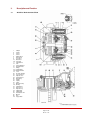
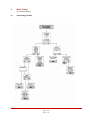
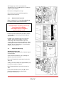
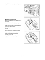
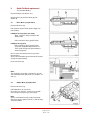
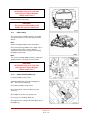
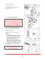
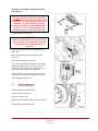
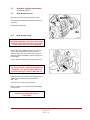
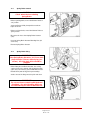
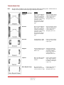
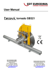
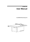
Refers to Products in the Asia Pacific Region Only
Refers to Products in the Asia Pacific Region Only
TRAILER AIR SUSPENSIONS
No:
97117 - 112
Subject: Service Manual
Date:
April 2009
Revision:
G
Page
1.
Exploded view of brake............................................................2
2.
General information .................................................................3
3.
Description and function ..........................................................4
4.
Safety instructions for service work.........................................6
5.
Brake testing ............................................................................7
6.
Pad replacement.................................................................... 13
7.
Tappet with boot replacement ............................................... 15
8.
Calliper suspension sealing................................................... 18
9.
Guide pin bush replacement.................................................. 19
10. Calliper replacement.............................................................. 20
11. Carrier replacement ............................................................... 23
12. Actuation cylinder replacement ............................................. 24
Troubleshooting............................................................................... 27
THE BOLER COMPANY
COPYRIGHT ©2006
HENDRICKSON ASIA PACIFIC PTY LTD
ALL RIGHTS RESERVED
Page 1 of 27
97117 —112
ABN 21 004 992 769
5 Abbotts Road, P.O. Box 1063, Dandenong, Victoria 3175 Australia
Phone 61.3.9767.3400
Fax 61.3.9767.3495
www.hendrickson.com.au
Refers to Products in the Asia Pacific Region Only
1.
Overall view
1.1
Axial Disc Brake Components
1
2
4
5
6
7
9
10
10a
11
12
13
Calliper
Carrier
Sleeve
Sleeve
Rubber Bush
Brass Bush
Inner Boot
Outer Boot
Steel Cap
Pad Retainer
Pad
Tappet with Boot
18/1
18/2
26
31
31a
37
39
40
44
45
58
161
Spring Brake
Brake Chamber
Spring Clip
Outer Boot Clip
O-Ring
Adjuster Cap
Calliper Bolt
Calliper Bolt
Pad Retainer Pin
Washer
Ring
Tappet Bush
*) possible variants by items 10a & 31a
if short rubber bush (6) (sleeve ring is
placed centrally),
Calliper bolts (39) & (40) are identical
Page 2 of 27
97117 —112
Refers to Products in the Asia Pacific Region Only
1.2
Brake Discs
(For “Axial Disc Brake”)
When replacing the discs, please also refer to the instructions of the Vehicle Manufacturer.
When replacing discs, please adhere to the recommended bolt tightening torques.
The use of non-approved brake discs will reduce levels of safety and invalidate warranty.
Brake discs can be ordered through Hendrickson.
2.
2.1
General Information
(for “Axial Disc Brake”)
Service Tools
Part Number
98596-009
Description
All parts listed below are included in this kit*
II 19252
Press-in tool for Tappet and Boot (13)
II 19253
Pull-in tool for Inner Boot (9)
II 19254
Pull-In / Out tool for Brass Bush (7)
II 32202
Wedged fork for removal of Tappet and Boot (13)
II 26797
Grooving tool for Brass Bush (7)
Z001105
Press-in tool for Steel Cap (10a)
*Parts not available individually
2.2
Lubrication
Hendrickson
Part Number
98793-004
98793-005
Part Number
Description
Colour
2)
II 14525
Renolit HLT2
White
II 32793
Syntheso GL EP1
Green 2)
2)
Important Note: The correct grease MUST be used for each Bush
2.3
Torque Requirements
Item Number
39 + 40
18
Description
Calliper bolts M16 x 1.5 – 10.9
Actuator Mounting Nuts M16 x 1.5
Toowoomba Steel Hub
Rotor to Hub Mounting Bolts
Conmet Alloy Hub
Rotor to Hub Mounting Bolts
Not Shown
Calliper to Torque Plate Bolts M20 x 2.5
Page 3 of 27
97117 —112
Application
Brass Bush (7)
Rubber Bush (6)
Torque
(Nm)
285-300
Torque
(Lbs/ft)
210-220
180-210
300-340
130-150
220-250
220-250
440-510
160-185
325-375
Refers to Products in the Asia Pacific Region Only
3.
Description and Function
3.1
Axial Disc Brake Sectioned View
1
2
4
5
6
7
9
10
10a
11
12
13
16
17
18/1
18/2
19
20
22
23
24
26
27
28
30
31
31a
32
33
37
39
40
44
45
46
161
Calliper
Carrier
Sleeve
Sleeve
Rubber Bush
Brass Bush
Inner Boot
Outer Boot
Steel Cap
Pad Retainer
Pad
Tappet with Boot
Threaded Tube
Bridge
Spring Brake
Brake Chamber
Lever
Eccentric Bearing
Inner Seal Cap
Adjuster Unit
Turning Device
Spring Clip
Spring
Spring
Chain
Outer Boot Clip
O-Ring
Chain Wheel
Wear Sensor
Adjuster Cap
Calliper Bolt
Calliper Bolt
Pad Retainer Pin
Washer
Disc
Tappet Bush
Page 4 of 27
97117 —112
Refers to Products in the Asia Pacific Region Only
3.2
3.2.1
Description of Operation
(Floating Calliper principle)
Brake actuation
During actuation, the Push Rod of the Actuator
18/1 or 18/2) moves the Lever (19). The input
forces are transferred via the Eccentric Bearing
(20) to the Bridge (17). The force is then
distributed by the Bridge (17) and the two Threaded
Tubes (16) to the Tappets (13) and finally to the
inboard Pad (12).
After overcoming the running clearance between
the Pads and the Disc, the reaction forces are
transmitted to the outboard Pad (12). The
clamping forces on the Pads (12) and the Disc (46)
generate the braking force for the wheel.
3.2.2
Brake release
After releasing the air pressure, the two Return
Springs (27/28) push the Bridge (17) and Lever
(19) back to the start position; this ensures a
running clearance between Pads and Disc is
maintained.
3.2.3
WARNING !
Before starting repair work, ensure the
service brake and parking brake are not
applied and that the vehicle cannot roll away.
Please follow repair manual instructions and adhere
to the wear limits of the Pads and the Discs – see
Section 5.3.
Use only recommended tools – see Section 2.1.
Tighten bolts and nuts to the recommended torque
values – see Section 2.4.
After re-fitting the wheel according to the Vehicle
Manufacturer’s recommendations, please ensure that
there is sufficient clearance between the Tyre
Inflation Valve, the Calliper and the wheel rim, to
avoid damage to the Valve.
After service work:
Check the brake performance and the system
behaviour on a rolling road or by actual road test.
Brake adjustment (automatic)
To ensure a constant running clearance between
Disc and Pads, the brake is equipped with a low
wearing, automatic adjuster mechanism.
The Adjuster (23) operates with every cycle of
actuation due to the mechanical connection with
Lever (1(0. As the Pads and Disc wear, the
running clearance increases. The Adjuster (23)
and Turning Device (24) turn the Threaded Tubes
(16) by an amount necessary to compensate for
this wear. The total running clearance (sum of
clearance both sides of Disc) should be between
0.6 and 0.9mm; smaller clearances may lead to
overheating problems.
4. Safety Instructions for service work
(for “Axial Disc Brake”)
Please also refer to the relevant safety instructions
for repair work on commercial vehicles, especially
for jacking up and securing the vehicle.
Page 5 of 27
97117 —112
Refers to Products in the Asia Pacific Region Only
4.
Brake Testing
(for “Axial Disc Brake”)
4.1
Fault finding procedure
Page 6 of 27
97117 —112
Refers to Products in the Asia Pacific Region Only
5.2
Adjuster check
Adjuster has failed and the Calliper must be replaced.
WARNING !
Before starting repair work, ensure the
service brake and parking brake are not
applied and that the vehicle cannot roll away.
Remove wheel.
The calliper assembly should be pushed inboard on
its guide pins. Using a suitable tool, press the
inboard pad (12) away from the Tappets and check
Tappet and inboard pad backplate – it should be
between 0.5mm & 1.0mm. If the running clearance
is too small or large, the adjuster may not be
functioning correctly and should be checked as
follows.
Remove Cap (37).
WARNING !
Do not overload or damage the Adjuster (23).
Use only 8mm Ring Spanner or ¼” drive
Socket with a lever length no greater than
100mm.
use an Open Ended Spanner since
this may damage the Adjuster shaft.
The Adjuster should be turned counter-clockwise
for 2 or 3 clicks (increasing running clearance).
WARNING !
Make sure that the Ring Spanner or Socket
can burn freely during following procedure.
By applying the brake 5-10 times (about 2 Bar) the
Spanner or Socket should turn clockwise in small
increments if the Adjuster is functioning correctly
(see notes below).
If Pads are not being changed, Cap (37) should be
replaced having lightly greased it with Renolit HLT2
(Refer to Page 5 for part number).
NOTE:
As the number of applications increases,
incremental adjustment will decrease.
NOTE:
If the Spanner or Socket does not turn, turns only
with the first application or turns forward and
backward with every application, the automatic
Page 7 of 27
97117 —112
Refers to Products in the Asia Pacific Region Only
5.3
Wear Limits of Pads and Discs
WARNING !
For optimum safety, stay within the Disc and Pad Wear Limits
Pads
The thickness of the Pads must be checked
regularly dependent on the usage of the vehicle.
The Pads should be checked corresponding to any
legal requirements that may apply.
If no Wear Indicator has been connected this
should be at least every 3 months.
If friction material is less than 2mm (see E), the
Pads must be replaced.
Discs
Measure thickness at thinnest point. Avoid
measuring near the edge of the disc as a burr may
be present.
A = Disc thickness (new condition) 45mm
B = Disc thickness (worn) 37mm. Disc must be
replaced
C = Overall thickness of Pad (new condition)
30mm
D = Backplate 9mm
E = Minimum thickness of friction material 3mm
F = Minimum allowed thickness in worn condition
for backplate and friction material 11mm
(replacement of Pads necessary)
If wear dimension B 37mm Disc should be
renewed together with Pads
Wear dimension B = 37mm must not decrease.
WARNING !
If these recommendations are ignored, there is a danger of brake failure
Page 8 of 27
97117 —112
Refers to Products in the Asia Pacific Region Only
Check Disc at each change of Pads for grooves
and cracks.
The diagram shows possible conditions of the
surface.
A1 = Small cracks spread over the surface
are allowed
B1 = Cracks less than 1.5mm deep or wide,
running in a Radial direction, are allowed
C1 = Grooves (circumferential) less than 1.5mm
wide are allowed
D1 = Cracks in the vanes are not allowed and the
Disc MUST BE REPLACED.
a = Pad contact area
Note:
In case of surface conditions A1-C1, the Disc can
continue to be used until the minimum thickness of
37mm is reached.
Knorr-Bremse Discs are normally service-free and
grinding when changing Pads is not necessary.
However, grinding could be useful, e.g. to increase
the load-bearing surface of the Pads after severe
grooving on the entire friction surface has occurred.
To meet safety requirements, the minimum
thickness after regrinding is > 37mm.
In addition, the recommendation of the Vehicle
Manufacturer MUST be followed.
WARNING !
If these recommendations are ignored, there is a danger of brake failure.
If the Pads are worn down to the backplate or if Disc wear is excessive,
brake performance will be severely affected and may be lost completely.
Page 9 of 27
97117 —112
Refers to Products in the Asia Pacific Region Only
5.3.1
Brake Wear Check using Guide Pin (for all Axial Disc Brakes, except those listed in Section 5.3.2 –
These Callipers do not have the rib in position B (see also Section 5.3.2).
The condition of the Pads can be visually
determined without removing the road wheel by
noting the position of the Fixed Sleeve (4) in the
Floating Calliper (1).
B = without rib (see also Section 5.3.2)
C = pin protrusion – shown in new condition
D = minimal pin protrusion – Pads and Disc must
be checked with road wheel removed
If dimension ‘C’ is less than 1mm, a more accurate
check of the Pads and Disc must be made.
If necessary change the Pads – see Section 6.
Page 10 of 27
97117 —112
Refers to Products in the Asia Pacific Region Only
5.3.2
Brake Wear Check using Guide Pin (Only for Axial Disc Brakes SB 7541, SB 7551 to SB 7629,
SB 7639
- These Callipers do have the rib in position B (see also Section 5.3.1)
The condition of the Pads can be visually
determined without removing the road wheel by
noting the position of the Fixed Sleeve (4) in the
Floating Calliper (1).
B = with rib (see also Section 5.3.1)
C = new condition
D = 18mm or more, Pads and Disc must be
checked with road wheel removed.
If the head of the Fixed Sleeve (4) is inside the
Rubber Bush (6) by a dimension D greater than
18mm, then a more accurate check of the Pads and
Disc must be made.
If necessary change the Pads – see Section 6.
Page 11 of 27
97117 —112
Refers to Products in the Asia Pacific Region Only
5.
Pad replacement
(for “Axial Disc Brake”)
WARNING !
Before starting repair work, ensure the service
brake and parking brake are not applied and
that the vehicle cannot roll away.
6.1
Pad removal
Take the wheel off (refer to Vehicle Manufacturer’s
recommendations).
Remove Clip (26) and Washer (45), push down the
Pad Retainer (11) and remove Pin (44).
If the Pad Retainer (11) is corroded, it should be
replaced.
Important
Before removing Pads it is strongly recommended
that the Adjuster mechanism is checked for correct
operation (see Section 5.2).
WARNING !
Do not overload or damage the Adjuster (23).
Use only 8mm Ring Spanner or ¼” drive
Socket with a lever length no greater than
100mm.
use an Open Ended Spanner since
this may damage the Adjuster shaft.
Remove Cap (37).
Turn the Adjuster counter-clockwise until Pads can
be removed. A clicking noise will be heard during
this procedure.
Push inboard Pad (12) toward Actuator.
Pull out both Pads (12).
6.1.1
Tappet Boot Check
The Adjuster (23) should be screwed clockwise until
the boots are clearly visible.
The Boots should not show any damage.
Check the attachment of the Boots into the Calliper
housing.
Important
Any ingress of water or dirt past the Tappet Boot will
lead to corrosion and affect the function of the
Actuation Mechanism and Adjuster Unit.
If damaged, the Boot and Tappet must be replaced
(see Section 7).
Page 12 of 27
97117 —112
Refers to Products in the Asia Pacific Region Only
6.1.2
Calliper guidance check
Following Pad removal (Section 6.1).
Using hand pressure only (no tools), the Calliper (1)
must slide freely over the whole length of the Guide
Pin arrangement >30mm.
During this operation the Sleeve (5) is sealed by the
Boot (9) and Cap (10) or Steel Cap (10a) and ORing (31a). These must show no signs of damage.
Check that these are correctly seated.
6.2
Pad fitting
WARNING !
Pads must be changed as an axle set
and NOT individually.
Use only Pads which are permitted by the
vehicle manufacturer, axle manufacturer and
brake manufacturer.
Failure to comply with this may invalidate the
vehicle manufacturer’s warranty.
Note:
Before placing the Pads into the Carrier, the
Adjuster (23) must be further de-adjusted by rotating
it counter clockwise.
Clean the Pad abutments.
Push Calliper (1) outboard and fit the outboard Pad
(12).
For fitting the inboard Pad (12) push Calliper (1) in
the opposite direction.
If fitted, replace Wear Indicators and fittings /
brackets etc. See page 5 or 7.
WARNING !
Do not overload or damage the Adjuster (23).
Use only 8mm Ring Spanner or ¼” drive
Socket with a lever length no greater than
100mm.
use an Open Ended Spanner since
this may damage the Adjuster shaft.
Rotate the Adjuster clockwise until the Pads come
into contact with the Disc. Then turn back the
Adjuster 2 clicks.
Page 13 of 27
97117 —112
Refers to Products in the Asia Pacific Region Only
The hub should turn easily by hand after having
applied and released the brake.
The Cap (37) must then be replaced having lightly
greased it with Renolit HLT2 (refer to Page 5 for part
number).
After setting the Pad Retainer (11) into the groove of
the Calliper (1), it must be pushed in to enable the
positioning of Pad Retainer Pin (44).
Fit washer (45) and Spring Clip (26) to the Pad
Retainer Pin (44) (use only new parts).
Our recommendation is fitting Washer (45) and
Spring Clip (26) pointing downwards (see diagram.
)
Wheel mounting (refer to Vehicle Manufacturer’s
recommendations).
IMPORTANT !
New Pads need bedding in. Heavy or long
duration braking should initially be avoided.
7.
7.1
Tappet with Boot replacement
(for “Axial Disc Brake”)
Tappet with Boot removal
Note:
It may be easier to remove the Calliper from the axle
to replace the Tappets of the Calliper (see Section
10.1).
The Adjuster (23) must be screwed clockwise until
the Boots can be reached.
If the Calliper has been removed from the vehicle
care must be taken not to overrun the threads (see
Section 7.1.1).
To remove the Tappet Boot from the Calliper bore, a
Screwdriver should be used to deform the Boot
location ring – see diagram.
WARNING !
Great care must be taken not to damage the
Inner Seal since it is not a replacement item.
Page 14 of 27
97117 —112
Refers to Products in the Asia Pacific Region Only
The Tappets (13) can be removed from the
Threaded Tubes by using Wedge Fork A. (Refer to
Page 5 for part number.)
Remove the old Tappet Bush (116).
Check Inner Seal (arrow) and if damaged, the
Calliper must be replaced.
7.1.1
Adjuster thread inspection
Place an unworn Pad (12) into the outboard gap
to avoid overrunning of the Threaded Tubes.
IMPORTANT !
Threaded Tubes should not overrun the
inner thread of the Bridge.
The Calliper must be changed if
synchronisation is lost.
For the inspection of the threads, the tubes must be
screwed out (max. 30mm) by turning the Adjuster
(23) clockwise.
If Calliper is not installed on axle, put a spacer E
(length = 70mm) into the Calliper (1) to avoid
overrunning of the Threaded Tubes (16) when
screwing them out (see illustration opposite). During
screwing, the threads can be checked for corrosion
damage. In case of water ingress or corrosion, the
Calliper must be replaced.
7.2
Tappet with Boot fitting
With Calliper fixed to axle:
Grease threads with Renolit HLT2. (Refer to Page 5
for part number.)
Screw back Threaded Tubes (16), by turning the
Adjuster (23) counter-clockwise.
Place new Tappet Bush (161) onto the head of the
Tube (16).
Sealing seat in the Calliper for Tappet with Boot (13)
must be clean and free of grease.
Place Tappet with Boot (13) onto the head of the
Tube.
Use Push-In Tool with the short strut (B) (refer to
Page 5 for part number) for positioning and
pressing-in the Boot (13).
Page 15 of 27
97117 —112
Refers to Products in the Asia Pacific Region Only
Using Tool B in reverse, the Tappet can be pressed
on.
With Calliper not installed on axle
Grease thread with Renolit HTL2 (refer to Page 5 for
part number).
Screw back Threaded Tubes (16), by turning the
Adjuster (23) counter-clockwise.
Sealing seat in the Calliper for Tappet with Boot (13)
must be clean and free of grease.
Place new Tappet Bush (161) onto the head of the
Tube (16).
Place Tappet with Boot (13) onto the head of the
Tube.
Use Push-In Tool with the long strut (B) (refer to
Page 5 for part number) for positioning and
pressing-in the Boot (13).
Using the Tool B in reverse, the Tappet can be
pressed on.
Page 16 of 27
97117 —112
Refers to Products in the Asia Pacific Region Only
8.
Calliper Suspension sealing
(Replacement of Inner Boot (9) )
(for “Axial Disc Brake”)
Remove Calliper (see Section 10.1)
Remove Ring (58).
Pull out Sleeve (5).
Push out Boot (9) with screwdriver.
Inspect and clean contact area of Boot (9).
Put new Boot (9) into the Sleeve (arrow) of the
Tool C (refer to Page 5 for part number).
Position Sleeve with Boot (9) into the Calliper bore
and pull in.
Fit the Sleeve (5).
The Boot end must engage in the groove of the
Sleeve (5) (arrow). Lock with Ring (58) by pushing
until it engages.
Important:
Before fitting the Calliper the unsealed Sleeve with
the Rubber Bush should be checked for its ability to
slide.
Fit Calliper (see Section 10.2).
Page 17 of 27
97117 —112
Refers to Products in the Asia Pacific Region Only
9
Guide Pin Bush replacement
(for “Axial Disc Brake”)
Remove Calliper (see Section 10.1)
Remove Sleeve (5) and Inner Boot (9) (see
Section 8).
9.1
Brass Bush (7) replacement
Remove old Sleeve (5).
Pull out Bush (7) with Tool D (refer to Page 5 for
part number).
If Calliper has no groove (see arrow)
(Note: Groove is always located on the
inboard side)
Pull in new Brass Bush (7) with Tool D.
If Calliper has a groove
Pull in new Brass Bush (7) with Tool D.
To prevent longitudinal displacement use
Tool F (refer to Page 5 for part number) to
create new groove.
Check contact area of Brass Bush (7) for burrs.
Remove burrs.
Grease Bush with white Grease Renolit HLT2 (refer
to Page 5 for part number).
Insert new Sleeve (5).
Note:
The Guide Pins Kit contains new Sleeves (4) & (5)
and new Calliper Bolts (39) & (40) (see Sections 1.2
and 1.4).
9.2
Rubber Bush (6) replacement
Remove old Sleeve (4).
Pull Rubber Bush (6) out of bore.
Check bore for corrosion, clean if necessary with
Corrosion protection paint (e.g. Zinc spray).
Note:
Grease new Rubber Bush (6) inside and outside
with green Grease Syntheso GL EP 1 (refer to Page
5 for part number).
Page 18 of 27
97117 —112
Refers to Products in the Asia Pacific Region Only
Deform new Rubber Bush (6) and push from the
inner side of the Calliper into the bore.
Push Rubber Bush (6) so that the outer positioning
ring locates in the groove (see arrows).
IMPORTANT !
Under no circumstances must the white
Grease (containing mineral oil) be used for
lubricating the Bush or Sleeve. Use only
synthetic based green Grease
(refer to Page 5 for part number).
Note:
The Guide Pins Kit contains new Sleeves (4) & (5)
and new Calliper Bolts (39) & (40).
Assemble Sleeve (4).
Re-fit Calliper (see Section 10.2).
Important:
Torque Calliper Bolts to 285+25 Nm and check that
the Calliper slides easily.
10
Calliper replacement
10.1
Calliper removal
(for “Axial Disc Brake”)
Remove Pads (see Section 6.1).
Remove Actuator (see Section 12.1 and 12.3).
Remove Outer Boot Clip (31) and take off Outer
Boot (10).
Note:
As well as Callipers with Outer Boot (10) and Outer
Boot Clip (31) there are versions with Steel
Cap (10a) and O-Ring (31a) available.
On models with Steel Caps (10a) and O-Rings
(31a), place Tool G (refer to Page 5 for part number)
onto the Steel Cap and tighten the threaded pin by a
hexagon socket spanner. Then use hammer as
shown.
Remove Cylinder Bolts (39 and 40).
Page 19 of 27
97117 —112
Refers to Products in the Asia Pacific Region Only
WARNING !
Hold Calliper only at its outer side.
Never get your fingers between
Calliper and Carrier !
Remove Calliper from Carrier.
WARNING !
The opening or dismantling of the
Calliper has not been authorised.
10.2
Calliper fitting
The correct choice of Calliper must be ensured by
checking the Part No. on the label (arrow, picture
above).
Note:
Service Exchange Callipers have a blue label.
The Service Exchange Calliper has a plastic cap or
an adhesive tape in the are of the Actuator
attachment. Remove the cap tape after installing
the Calliper (see arrow).
Note:
The service exchange Calliper includes sealing and
guiding elements. The Pads are not included.
WARNING !
Hold Calliper only at its outer side.
Never get your fingers between
Calliper and Carrier !
10.2.1
Calliper with Outer Boot (10)
Locate the Calliper to the Carrier.
Screw-in Calliper Bolts (39 & 40) and tighten to
+25
285 Nm (use only new parts).
Check that the Calliper slides easily.
Check the position of the Inner Boot (9) on the
Sleeve (5).
Check Adjuster function (see Section 5.2).
If necessary use new Outer Boot (10).
Check grease-free seating of the Outer Boot (10) on
the Calliper (1).
Page 20 of 27
97117 —112
Refers to Products in the Asia Pacific Region Only
Tighten Outer Boot Clip (31).
Fit the Pads (see Section 6.2).
Attach Brake Chamber or Spring Brake (see
Sections 12.2 or 12.4).
10.2.2
Calliper with Steel Cap (10a)
IMPORTANT !
It is only allowed to replace the Outer Boot
(10) by the Steel Cap (10a) when replacing the
Sleeve (5), the O-Ring (31a) and the Screw (40)
at the same time. Replace only after
permission by Axle or Vehicle Manufacturer.
On SB 6 … (19.5”) only permissible after
manufacturing date A0026 (see type plate).
It may be easier to remove the Calliper and the
Carrier from the axle to replace the Steel Cap.
Assembly at the Vehicle:
The fitting must be carried out with Pads still
installed.
• Clean area.
• Using the Grease supplied (refer to Page 5 for
part number), lightly lubricate the O-Ring and
place it over the cast spigot (see sketch).
• Remove Threaded Pins from assembly Tool G
to avoid damage of the Steel Cap.
• Hold the new Steel Cap on the end of the
Spigot. By using a suitable press or special
assembly tool (refer to Page 5 for part number)
and a hammer, press the Steel Cap fully on the
spigot making sure not to deform the Cap.
After removal the Steel Cap and the O-Ring must
not be refitted.
IMPORTANT !
The Steel Cap (10a) and the O-Ring
must only be used once.
Page 21 of 27
97117 —112
Refers to Products in the Asia Pacific Region Only
Assembly on the Calliper and Carrier removed
from the axle:
IMPORTANT !
It is only allowed to replace the Outer Boot
(10) by the Steel Cap (10a) when replacing the
Sleeve (50), the O-Ring (31a) and the Screw
(40) at the same time. Replace only after
permission by Axle or Vehicle Manufacturer.
On SB 6… (19.5”) only permissible after
manufacturing date A0026 (see type plate).
Put the Calliper on the Carrier.
IMPORTANT !
Special threaded Screw (40) and Steel Cap
(10a) as well as the O-Ring (31a) must be
renewed whenever Screw (40) has been
removed.
Screw-in Calliper Bolts (39 & 40) and tighten to
285+25 Nm.
Check the position of the Inner Boot (9) on the
Sleeve (5).
Check that the Calliper slides easily.
In the shown clamping (e.g. vice) press the Calliper
against the Carrier as far as possible. The Inner
Boot (9) must be in compressed condition, this is to
prevent air being trapped inside of the Cap.
The assembly of the Steel Cap (10a) can now be
carried out as in Section “Assembly at the Vehicle”.
Check Adjuster (Section 5.2).
11
Carrier replacement
(for “Axial Disc Brake”)
Remove Calliper (see Section 10.1).
Remove Carrier (2) from axle.
Clean axle contact area.
Attach new Carrier with new bolts from Hendrickson.
Attach Calliper (see Section 10.2).
Page 22 of 27
97117 —112
Refers to Products in the Asia Pacific Region Only
12
Actuation cylinder replacement
12.1
Brake Chamber removal
(for “Axial Disc Brake”)
Disconnect air line from Brake Chamber (18/2).
Unscrew Brake Chamber Mounting Nuts (do not reuse them).
Remove Brake Chamber.
12.2
Brake Chamber fitting
IMPORTANT !
New Brake Chambers (18/2) have drain plugs
installed. Remove bottom plug (see arrows).
All other drain holes should be plugged.
Before fitting the new Brake Actuator, the sealing
surface (see arrow) must be cleaned, and the
Spherical Cup (19) in the Lever must be greased
with white Grease Renolit HLT2 (refer to Page 5 for
part number).
Surface area of the flange must be plain and clean.
IMPORTANT !
Do not use Grease containing molybdenum
disulphate. Use only Actuators which are
recommended by the Vehicle Manufacturer.
Attach Actuator with new Nuts (self-locking) (refer to
Page 5 for part number) and torque tighten to
180+30 Nm.
Connect air hose and check for leakage.
Make sure that hose is not twisted and that chafing
is not possible.
IMPORTANT !
Check function and effectiveness
of the brake.
Page 23 of 27
97117 —112
Refers to Products in the Asia Pacific Region Only
12.3
Spring Brake removal
CAUTION !
Chock wheels before releasing
Spring Brake.
Release parking brake, move Hand Control Valve to
‘run’ position.
Screw-out Release Bolt (arrow) with a maximum
torque of 35 Nm.
Release air from brake, move Hand Control Valve to
‘park’ position.
Disconnect air hoses from Spring Brake Actuator
(18/1).
Unscrew Spring Brake Actuator Mounting Nuts (do
not re-use).
Remove Spring Brake Actuator.
12.4
Spring Brake fitting
IMPORTANT !
New Spring Brake Actuators (18/1) have drain
plugs installed. Remove bottom plug (see
arrows). All other drain holes should be
plugged.
Before fitting the new Brake Actuator, the sealing
surfaces have to be cleaned, and the Spherical Cup
(19) in the Lever must be greased with white Grease
Renolit HLT2 (refer to Page 5 for part number).
Surface area of the flange must be plain and clean.
IMPORTANT !
Do not use Grease containing Molybdenum
disulphate. Use only Actuators which are
recommended by the Vehicle Manufacturer.
Page 24 of 27
97117 —112
Refers to Products in the Asia Pacific Region Only
Attach Actuator with new Nuts (self-locking) and
torque tighten to 180+30 Nm.
Connect air hose, ensuring that hoses are not mixed
up.
Make sure that hoses are not twisted and that
chafing is not possible.
Release parking brake, move Hand Control Valve to
‘run’ position, and check for leakage.
Screw in Spring Brake Release bolt to maximum
70 Nm.
IMPORTANT !
Check function and effectiveness
of the brakes.
For further information please Contact a member of our Repairer Network on 1300 130 960
Page 25 of 27
97117 —112
Refers to Products in the Asia Pacific Region Only
TROUBLESHOOTING
Note:
The disc pads used with the rotor may indicate problems within your braking system. Shown below are
examples of disc pad wear which may help you identify these problems.
PROBLEM
Disc Brake Pad Wear
Chipped
CAUSE
SOLUTION
Excessive heat build-up in
brake system – calliper or
calliper piston hanging up
creating constant friction –
rear brakes not functioning
effectively, causing
disproportionate braking
energy on the front disc
pads.
Check rear brakes, replace
calliper and calliper piston,
replace pads and check
rotor for damage. If
damaged, replace rotor.
Cracked
Excessive heat build-up in
brake system – calliper or
calliper piston hanging up
creating constant friction –
rear brakes not functioning
effectively, causing
disproportionate braking
energy on the front disc
pads.
Check rear brakes, replace
calliper and calliper piston,
replace pads and check
rotor for damage. If
damaged, replace rotor.
Grooved
Foreign material or debris
embedded in brake pads.
Rotors need to be turned
(refaced) or replaced and
replace pads.
Stepped
Pads not installed correctly
– pads not in full contact
with the rotor.
Replace the guide pins,
mounting bolts, bushing
and calliper hardware.
Replace pads and check
rotor for damage. If
damaged, replace rotor.
Tapered
Worn out calliper bushings
and/or worn out calliper
hardware.
Replace calliper bushings
and/or calliper hardware,
replace pads, check rotor
for damage. If damaged,
replace rotor.
Worn Beyond Usage
Disc pads allowed to
remain in service beyond
normal safe limits of usage.
Replace pads and check
rotor for damage. If
damaged, replace rotor.
Page 26 of 27
97117 —112
Refers to Products in the Asia Pacific Region Only
NOTES
Page 27 of 27
97117 —112