1
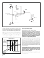
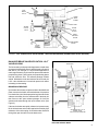
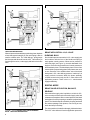
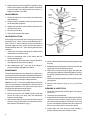
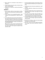
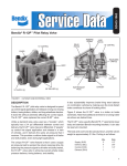
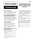
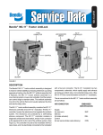
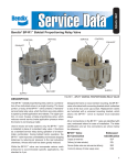
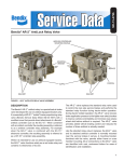
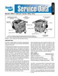
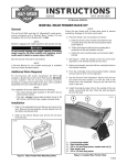
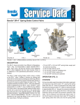
SD-03-953
®
Bendix® LQ-5™ Bobtail Ratio Valve
1.5"
3/8 P.T.
SUPPLY PORT
.340”
MOUNTING
HOLES (2)
STAMPED LQ-5
REPLACEMENT
PC. NO.
1/8 P.T.
CONTROL PORT
3/8 P.T.
DELIVERY PORT
FIGURE 1 - LQ-5™ BOBTAIL RATIO VALVE
DESCRIPTION
The LQ-5™ bobtail ratio valve is used on the front (steering)
axle of tractor air brake systems to reduce brake application pressure during normal tractor-trailer operation. It is
designed for tractor systems only and replaces the existing
front axle limiting valve. It is not to be used on straight trucks
or towing trucks. Also, a quick release valve must be installed between the LQ-5™ valve delivery and the brake
chambers.
Although it is not mandatory, the LQ-5™ valve is used in
conjunction with the BP-R1™ bobtail brake proportioning relay
valve, only when a customer specifies a front axle ratio valve.
The BP-R1™ valve and LQ-5™ valve combine to reduce
stopping distance and improve tractor control in bobtail mode.
(For more information on the BP-R1™ valve, see SD-03-1067.)
IMPORTANT: Do not replace the BP-1™ front brake proportioning valve with the LQ-5™ valve. The LQ-5™ valve
will not function properly in the BP-1™ valve system.
GENERAL
Caution: The LQ-5™ valve can replace the LQ-4™ ratio valve
on tractors. The LQ-5™ valve control port must be connected
to the trailer supply line. When the tractor is disconnected
from the trailer, bobtail tractor braking performance is improved
because full brake valve pressure will be applied to the
steering axle brakes.
OPERATION
After an initial delivery, the LQ-5™ valve limits front axle brake
pressure during normal tractor-trailer operation. The LQ-5™
valve has two spring-loaded pistons: a blend back piston
and a proportioning piston. The “stepped” proportioning piston
determines actual air pressure reduction and the blend back
piston allows the valve’s delivery pressure to “blend back”
and reach a 1:1 ratio during high pressure brake applications.
1
BRAKE
CHAMBER
PP-7™
TRAILER
SUPPLY
VALVE
BRAKE
VALVE
SUPPLY
QUICK RELEASE
VALVE
LQ-5™
VALVE
LP-3™ LOW
PRESSURE
INDICATOR
GAUGE
DELIVERY
BRAKE CHAMBER
FRONT AXLE
SERVICE RESERVOIR
FIGURE 2 - LQ-5™ BOBTAIL RATIO VALVE INSTALLATION
The LQ-5™ valve also allows full service pressure to pass
through it when the trailer supply valve (red octagonal button)
is pulled out—when the tractor is running in bobtail mode.
Note: LQ-5™ valve control pressure, which comes from the
trailer supply line, will vary. As a result, the LQ-5™ valve
delivery and blend back ranges will also vary, because the
blend back piston works against control pressure. Figure 3
shows the LQ-5™ valve delivery range at two control
pressures: 90 psi and 120 psi.
CONTROL PRESSURE
120 PSI
FRONT
AXLE
BRAKE
CHAMBER
PRESSURE
CONTROL
PRESSURE
90 PSI
NO CONTROL
PRESSURE
INITIAL
DELIVERY
PRESSURE
0
Brake Application—LQ-5™ Valve Limiting
During tractor-trailer operation, the trailer supply valve (red
octagonal button) is depressed and delivers air pressure
simultaneously to the trailer and to the LQ-5™ valve control
port. Air pressure enters the LQ-5™ valve control port and
displaces the blend back piston, against the resistance of
its spring, until the piston contacts the cover.
Control pressure holds the blend back piston against the
cover and the “initial delivery” spring forces the proportioning
piston to its seat in the body, which opens the inlet. The
“initial delivery” pressure is designed to ensure that the brake
linings contact the brake drums before proportioning occurs.
The exhaust valve is sealed due to its spring. Brake valve air
pressure enters the supply port, moves through the center
of the pistons, around the inlet/exhaust valve, and out to the
front axle actuators.
Air pressure being delivered to the brake actuators is also
present beneath the proportioning piston. Because the area
on the delivery side of the proportioning piston is larger than
that on the supply side, the delivery side needs less air
pressure to apply the same force.
BRAKE VALVE DELIVERY
PRESSURE
FIGURE 3 - LQ-5™ BOBTAIL RATIO VALVE PERFORMANCE
CURVE
2
TRACTOR-TRAILER MODE
Therefore after the initial delivery pressure, the LQ-5™ valve
delivers less air pressure to the front axle than it receives
from the brake valve.
COVER
DUAL
BRAKE
VALVE
BLEND
BACK
SPRING
BODY
TRAILER
SUPPLY
VALVE
BLEND
BACK
PISTON
INITIAL
DELIVERY
PISTON
PROPORTIONING
PISTON
FRONT
BRAKE
CHAMBER
INLET/
EXHAUST
VALVE
FIGURE 4 - LQ-5™ BOBTAIL RATIO VALVE LIMITING: TRACTOR-TRAILER MODE (SHOWN DURING INITIAL DELIVERY)
BALANCED BRAKE VALVE APPLICATION - LQ-5™
VALVE HOLDING
BRAKE VALVE APPLICATION
PRESSURE
The forces acting on the proportioning piston are equal when
air pressure beneath the piston is approximately one-half of
that above. (For example, if a 40 psi brake application is
made, approximately 20 psi would be present beneath the
proportioning piston.) At this point, the proportioning piston
lifts and closes the inlet. The exhaust passage remains
sealed. With both the inlet and exhaust valves closed, the
LQ-5™ valve is balanced—front axle air pressure is neither
increasing nor decreasing.
BRAKE VALVE RELEASE
Upon brake valve release, air pressure above the blend back
piston returns to the brake valve and exhausts. Air pressure
from the delivery line lifts the proportioning piston and inlet/
exhaust valve away from the exhaust seat in the body. Air
then flows out the open exhaust passage. Air from the
actuators exhausts through the quick release valve. (See
Figure 2.)
If the service brakes are rapidly released, air pressure may
lift the inlet/exhaust valve further against the relatively light
resistance of the valve spring. Air would then also flow back
through the open inlet and out to the brake valve.
APPROXIMATELY 1/2 OF
BRAKE VALVE
APPLICATION PRESSURE
FIGURE 5 - LQ-5™ BOBTAIL RATIO VALVE HOLDING:
TRACTOR-TRAILER MODE
3
FIGURE 6 - LQ-5™ BOBTAIL RATIO VALVE RELEASING:
TRACTOR-TRAILER MODE
FIGURE 8 - LQ-5™ BOBTAIL RATIO VALVE MODE
When air pressure beneath the proportioning piston depletes
to less than approximately 8 psi, the valve spring is able to
seat the exhaust valve. The “initial delivery” spring keeps
the inlet open and allows air from the LQ-5™ valve delivery to
flow through the valve, out the supply and back to the brake
valve.
BRAKE APPLICATION—LQ-5™ VALVE
BLENDING BACK
Service brake pressure enters the LQ-5™ valve supply port
and combines with the force of the blend back spring to
work against control pressure. When service pressure is
sufficiently high (see Figure 3), the total downward force
begins to overcome the upward force of control pressure on
the blend back piston. The blend back piston is forced into
contact with the proportioning piston. Both pistons now move
as one. Because of the added surface area of the blend
back piston, LQ-5™ valve delivery pressure “catches up” as
supply pressure increases. When the piston assembly
contacts its seat in the body, the LQ-5™ valve delivers full
application pressure. There is then a 1:1 ratio between
supply and delivery.
BOBTAIL MODE
BRAKE VALVE APPLICATION, BALANCE,
RELEASE
When the trailer supply valve is pulled out, air in the LQ-5™
valve control port flows back to the trailer supply valve and
exhausts to atmosphere. With no control pressure, the blend
back piston is forced by its spring to contact the proportioning
piston. The inlet/exhaust valve is held by its spring and seals
the exhaust passage. Both pistons, now moving as one,
reach their stop in the body.
FIGURE 7 - LQ-5™ BOBTAIL RATIO VALVE BLENDING
BACK: TRACTOR-TRAILER MODE
4
This is the position for bobtail mode apply, hold and release.
The LQ-5™ valve delivers full service application pressure in
bobtail mode. Upon brake valve release, delivery air pressure
flows back through the LQ-5™ valve, to the brake valve and
out to atmosphere. Air from the actuators exhausts through
the quick release valve.
WARNING! PLEASE READ AND FOLLOW
THESE INSTRUCTIONS TO AVOID
PERSONAL INJURY OR DEATH:
When working on or around a vehicle, the following
general precautions should be observed at all times.
1. Park the vehicle on a level surface, apply the
parking brakes, and always block the wheels.
Always wear safety glasses.
2. Stop the engine and remove ignition key when
working under or around the vehicle. When
working in the engine compartment, the engine
should be shut off and the ignition key should be
removed. Where circumstances require that the
engine be in operation, EXTREME CAUTION should
be used to prevent personal injury resulting from
contact with moving, rotating, leaking, heated or
electrically charged components.
3. Do not attempt to install, remove, disassemble or
assemble a component until you have read and
thoroughly understand the recommended
procedures. Use only the proper tools and observe
all precautions pertaining to use of those tools.
4. If the work is being performed on the vehicle’s air
brake system, or any auxiliary pressurized air
systems, make certain to drain the air pressure from
all reservoirs before beginning ANY work on the
vehicle. If the vehicle is equipped with an AD-IS™
air dryer system or a dryer reservoir module, be
sure to drain the purge reservoir.
5. Following
the
vehicle
manufacturer’s
recommended procedures, deactivate the electrical
system in a manner that safely removes all
electrical power from the vehicle.
6. Never exceed manufacturer’s recommended
pressures.
7. Never connect or disconnect a hose or line
containing pressure; it may whip. Never remove a
component or plug unless you are certain all
system pressure has been depleted.
8. Use only genuine Bendix ® replacement parts,
components and kits. Replacement hardware,
tubing, hose, fittings, etc. must be of equivalent
size, type and strength as original equipment and
be designed specifically for such applications and
systems.
9. Components with stripped threads or damaged
parts should be replaced rather than repaired. Do
not attempt repairs requiring machining or welding
unless specifically stated and approved by the
vehicle and component manufacturer.
10. Prior to returning the vehicle to service, make
certain all components and systems are restored to
their proper operating condition.
PREVENTIVE MAINTENANCE
GENERAL
Perform the following tests and inspections at the prescribed
intervals. If the LQ-5™ valve fails to function as described or
if leakage is excessive, repair the valve or replace it with a
new or genuine Bendix remanufactured unit, available at any
authorized parts outlet.
Important: Review the Bendix Warranty Policy before
performing any intrusive maintenance procedures. A warranty
may be voided if intrusive maintenance is performed during
the warranty period.
No two vehicles operate under identical conditions, as a
result, maintenance intervals may vary. Experience is a
valuable guide in determining the best maintenance interval
for air brake system components. At a minimum, the valve
should be inspected every 6 months or 1500 operating hours,
whichever comes first, for proper operation. Should the valve
not meet the elements of the operational tests noted in this
document, further investigation and service of the valve may
be required.
OPERATION & LEAKAGE TESTS
OPERATION TEST
To properly test the LQ-5™ valve, use a pair of test gauges or
gauges of known accuracy.
1. With the trailer supply valve pushed in (tractor-trailer
mode), install two air gauges in the front axle service
system: one between the brake valve and the LQ-5™
valve and one at a front axle actuator.
2
Build system pressure to governor cut-out setting.
3. Make a service brake application with the foot valve and
have someone observe the gauges. When the gauge
between the foot valve and the LQ-5™ valve reaches 40
psi, the actuator gauge should read approximately 20
psi (±5 psi).
4. Make a full service brake application. Both gauges should
read the same pressure.
5. With the trailer supply valve pulled out (bobtail mode),
make a 30-40 psi service brake application. Both gauges
should read the same pressure.
6. Remove the test gauges.
LEAKAGE TEST
1. Build system pressure to governor cut-out. With the trailer
supply valve pushed in (tractor-trailer mode), apply a soap
solution to the LQ-5™ valve exhaust port. The leakage
should not exceed a 1" bubble in less than 3 seconds.
5
2. Make and hold a full brake application and apply a soap
solution to the exhaust port and around the cover where
it joins the body. The leakage should not exceed a 1"
bubble in less than 3 seconds.
VALVE REMOVAL
1. Secure the vehicle on a level surface by means other
than the brakes.
2. Drain air system completely, making sure all reservoirs
are at atmospheric pressure.
COVER
BLEND
BACK
SPRING
1
INITIAL
DELIVERY
SPRING
SPRING
SEAT
2
3. Identify and mark all air lines and their respective connections on the valve.
BLEND
BACK
PISTON
4. Disconnect all air lines.
5. Remove the valve from the vehicle.
VALVE INSTALLATION
If the vehicle has a front axle ratio or limiting valve (such as
the Bendix® LQ-4™ valve), it can be replaced with an LQ-5™
valve. The LQ-5™ valve control port must be connected to
the trailer supply line. Also, a quick release valve must be
installed between the LQ-5™ valve delivery and the brake
chambers.
6
5
4
3
PROPORTIONING
SPRING
BODY
1. Install all air line fittings making certain thread sealing
material does not enter the valve.
2. Mount the assembled valve on the vehicle with the
exhaust pointing down.
3. Reconnect all air lines to the valve using the identification made during Valve Removal, Step 3.
4. After installing the LQ-5™ valve, test all air fittings for
excessive leakage and tighten as needed.
DISASSEMBLY
The following disassembly and assembly procedures are
for reference only. Always have the appropriate maintenance
kit on hand and use its instructions in lieu of those presented
here. Refer to Figure 9 throughout the procedures.
Caution: The LQ-5™ valve may be lightly clamped in a bench
vise, but overclamping will damage the valve and cause
leakage and/or malfunction. If a vise is used, clamp around
the supply port and the mounting surface.
1. Remove all air fittings from the valve.
2. Before removing the four Phillips head screws that
secure the cover to the body, mark the relationship
between cover and body.
3. Remove and retain the screws and the metal tag with
the LQ-5™ valve piece number on it. Separate cover from
body. Remove and discard o-ring (1).
FIGURE 9 - LQ-5™ BOBTAIL RATIO VALVE
4. Remove the blend back and proportioning pistons from
the body.
5. Separate and retain the pistons. Remove and retain the
spring seat from the proportioning piston.
6. With a pair of needle nose pliers, grasp the end of the
valve spring (6) inside the proportioning piston. Remove
the spring by pulling and turning clockwise. Discard the
spring.
7. Remove and discard inlet/exhaust valve (5) from proportioning piston.
8. Remove and discard o-rings (2), (3), (4) from the
pistons.
CLEANING & INSPECTION
1. Clean all metal parts with mineral spirits or an equivalent solvent.
2. Thoroughly dry all metal parts.
3. Inspect interior and exterior of all metal parts that will be
reused for severe corrosion, pitting or cracks. Superficial corrosion and/or pitting on the exterior of the body
or cover is acceptable. Replace entire valve if interior of
body or cover shows signs of corrosion or pitting.
4. Inspect body and cover bores for deep scuffing or
gouges. Replace entire valve if either is found.
6
5. Make certain all air channels are clear and free of
obstruction.
6. Inspect all pipe threads and make sure they are clean
and free of thread sealant.
7. Inspect all air line fittings for corrosion and replace as
necessary.
ASSEMBLY
1. Before assembly, lubricate o-rings, pistons, and body
and cover bores with the lubricant in the Bendix maintenance kit.
2. Install o-rings (3 & 4) on proportioning piston. Install
o-rings (2 & 4) on blend back piston. Install o-ring (1) on
cover.
3. Place inlet/exhaust valve (5) into the inner diameter of
the proportioning piston and retain with valve spring (6).
Use needle nose pliers to install the spring by grasping
it on the bar that intersects its end and turning clockwise while pressing down. The bar must be away from
(not touching) the valve.
Note: Make sure spring coils do not overlap each other
as the spring compresses into the proportioning piston.
Also, make sure the valve is square, contacts the seat,
and doesn’t bind.
4. Insert the proportioning piston into the small bore of the
blend back piston and install the piston assembly in the
body.
5. Install spring seat into the piston assembly bore, small
end first.
6. Install the “initial delivery” spring on the inner wall of the
spring seat.
7. Install the blend back spring in the inner diameter of the
blend back piston so that it surrounds the “initial
delivery” spring.
8. Place the cover on the body in the proper position, as
marked in Disassembly, Step 2. Make sure the springs
are square when the cover is attached to the body.
9. Using the Phillips head screws and their lock-washers,
secure the cover to the body. Torque the screws to 5080 inch pounds.
10. Install all air line fittings, making sure thread sealing
material does not enter the valve.
11. Mount LQ-5™ valve on the vehicle and perform Operation
and Leakage Tests before returning the vehicle to
service.
7
8
BW1625 © 2004 Bendix Commercial Vehicle Systems LLC All rights reserved. 4/2004 Printed in U.S.A.