1
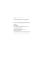
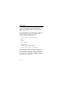
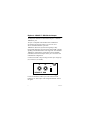
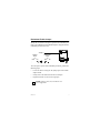
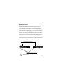
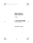
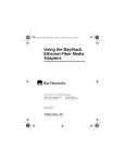
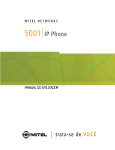
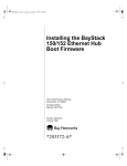
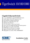
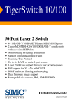
Using the BayStack
Ethernet Redundant
Fiber Media Adapter
Bay Networks, Inc. Corporate Headquarters
4401 Great America Parkway
Santa Clara, CA 95054
March 1996
893-863-A
8 Federal Street
Billerica, MA 01821
© 1996 by Bay Networks, Inc. All rights reserved.
Trademarks
Bay Networks, BayStack, and Bay Networks Press are trademarks of Bay
Networks, Inc. Other brand and product names are registered trademarks or
trademarks of their respective holders.
Statement of Conditions
In the interest of improving internal design, operational function, and/or reliability,
Bay Networks, Inc. reserves the right to make changes to the products described in
this document without notice. Bay Networks, Inc. does not assume any liability that
may occur due to the use or application of the product(s) or circuit layout(s)
described herein.
Related Publications
For more information about the installation and use of BayStackTM hubs and
optional equipment, refer to the following publications:
• Using the BayStack 10BASE-T Hubs
(Bay NetworksTM part number 893-839-B)
• Using the BayStack Ethernet Network Management Modules
(Bay Networks part number 893-841-A)
Ordering Bay Networks Publications
To purchase additional copies of this document or other Bay Networks publications,
order by part number from Bay Networks Press™ at the following numbers. You
may also request a free catalog of Bay Networks Press product publications.
• Phone: 1-800-845-9523
• FAX: U.S./Canada: 1-800-582-8000, International: 1-916-939-1010
Introduction
This guide describes the Bay Networks 10BASE-FL RDN Media
Adapter for the BayStack 10BASE-T Hubs and provides
instructions for installing, connecting, and configuring the
adapter in the hub.
Each BayStack 10BASE-FL RDN Media Adapter consists of one
optional 10BASE-FL port that provides flexible, redundant
backbone connectivity and two diagnostic LEDs.
This guide contains the following sections:
•
BayStack 10BASE-FL RDN Media Adapter
•
LEDs
•
Jumper
•
Remote Signaling
•
Redundant Links
•
Fiber Optic Cable Length Limitations
•
Installing a Media Adapter in a BayStack Hub
For more information about how the media adapter operates in
the hub, refer to Using the BayStack 10BASE-T Hubs (Bay
Networks part number 893-839-B). For more information about
hub compatibility with the 10BASE-FL RDN Media Adapter,
refer to Release Notes for the BayStack 10BASE-T Hubs (Bay
Networks part number 896-086-A).
893-863-A
1
BayStack 10BASE-FL RDN Media Adapter
The BayStack 10BASE-FL RDN Media Adapter is a modular
10BASE-FL port.
The port is compatible with the IEEE 802.3 10BASE-FL
specification for Ethernet running over 62.5/125 µm or
50/125 µm multimode fiber optic cable.
10BASE-FL (fiber link) asynchronous signaling is fully
interoperable with fiber optic interrepeater link (FOIRL). Remote
signaling and redundant links are also supported. The redundant
10BASE-FL media adapter provides Rem (remote) and Rdn
(redundant) status LEDs. Jumpers allow you to set remote and
redundant link configuration.
Connection is made to the port using two fiber optic straight-tip
(ST) connectors (Tx and Rx).
TX
RX
Rem
Rdn
10BASE-FL RDN
5957
For more information on fiber optic cable connection and
limitation, see “Fiber Optic Cable Length Limitations” later in
this guide.
2
893-863-A
LEDs
The BayStack 10BASE-FL RDN Media Adapter provides LEDs
to indicate remote signaling and redundant link status. These
LEDs are used in combination with the BayStack 10BASE-T
Hub “Media Adapter” LED to indicate the status of the active
and standby link.
Table 1 describes the redundant 10BASE-FL media adapter
LEDs.
Table 1. 10BASE-FL RDN Media Adapter LEDs
Label
Color
Meaning
Rem
Green
Fiber port is connected to a remote port that uses
remote signaling, and that port is not sending a
remote fault signal; both Tx and Rx connections
are good.
Amber
Fiber port is connected to a remote port that uses
remote signaling, but the Tx link to the remote Rx
connector detects a remote fault.
Off
Fiber port is not connected to another port that is
capable of remote signaling.
Green
Port is in redundant mode and detects no fault.
Amber
Port is in redundant mode, but this redundant port
connection has failed.
Off
Port is not in redundant mode.
Rdn
893-863-A
3
Table 2 describes the LED combinations of the hub “Media
Adapter” LED and the redundant fiber media adapter LEDs.
Table 2. LED status combinations
Hub LED Rem
Rdn
Meaning
Green
Green
Green
Active link in a redundant port pair; link
status is good, and remote link is good.
Amber
Green
Green
Standby link in a redundant pair; link status
is good, and remote link is good.
Amber
Green
Amber Standby link in a redundant pair is
partitioned or not ready; remote link is good,
but port is partitioned by detection of a local
fault (or possibly network management).
Amber
Amber Amber Standby link in a redundant pair is
partitioned for remote fault; check Tx link.
Off
Off
Amber Standby link in a redundant pair has failed
connection; check Tx and Rx links.
Remote Signaling
The BayStack 10BASE-FL RDN Media Adapter supports remote
signaling to indicate a far end receiver failure/remote fault
detection. Bay Networks uses a proprietary version of remote
fault signaling, because remote signaling is not specified in the
IEEE 802.3 10BASE-FL standard. Remote signaling is used to
verify the connection status of both the transmit and receive
fibers.
A Rem LED on the media adapter indicates remote signaling
status. For more information about this LED, see “LEDs” earlier
in this guide.
4
893-863-A
Redundant Enable Jumper
Jumper JP1 is used to set the port to operate in the redundant port
mode. The 10BASE-FL RDN Media Adapter is shipped with the
redundant port mode set to off.
Jumper 1
Default
mode
Redundant
mode
JP1
RDN
EN
JP1
RDN
EN
6771
To set the port to operate in the redundant port mode, perform the
following steps:
•
Locate the shunt covering the JP1 jumper pins on the media
adapter board.
•
Gently remove the shunt from the two far left pins.
•
Replace the shunt over the two far right pins.
NOTE: Jumpers JP2, JP3, and JP4 are not
user-configurable.
893-863-A
5
Redundant Links
The BayStack 10BASE-FL RDN Media Adapter supports
redundant links between Bay Networks BayStack Ethernet hubs,
System 5000 hubs, and other Bay Networks hubs that support
redundant links. If one fiber connection in a redundant pair
breaks, the standby link automatically takes over in less than 10
microseconds. This redundant link feature allows you to build
Ethernet dual-homing and mesh-type topologies. The port at both
ends of the fiber connection must support Bay Networks remote
signaling.
A jumper is used to set the redundant 10BASE-FL media adapter
port to operate in redundant mode with a 10BASE-FL fiber port
on another hub.
Active fiber link (Tx/Rx pair)
Standby fiber link (Tx/Rx pair)
= Redundant pairs
5977
6
893-863-A
For a pair of ports to operate in redundant mode:
•
Enable the JP1 jumper for redundant port mode on both of
the media adapters in the redundant port pair. For more
information about this jumper, see “Redundant Enable
Jumper” earlier in this guide.
•
Disable any redundant port mode on the port at the other end
of each redundant link.
A Rdn LED media adapter indicates redundant link status. For
more information about this LED, see “LEDs” earlier in this
guide.
893-863-A
7
Fiber Optic Cable Length Limitations
The 10BASE-F standard permits you to use fiber optic cables up
to 2000 meters long. However, the fiber connection must meet
the following criteria:
•
Optical power budget (shown in Table 3)
•
Ethernet repeater rules
For more information about simple rules for Ethernet network
compliance, refer to Using the BayStack 10BASE-T Hubs.
The optical power budget is shown in Table 3. Power loss in the
link cannot exceed the value for the type of fiber optic cable you
are using.
Table 3. 10BASE-FL RDN Media Adapter Power Budget
Parameter
62.5/125 µ m
50/125 µ m
Transmitted power (average)
–20 dBm
–25.7 dBm
Receiver sensitivity (average)
–32.5 dBm
–32.5 dBm
Optical power budget
12.5 dB
6.8 dB
Only in-line fiber-to-fiber connections (a connection between
two fibers terminated with fiber connectors, using a fiber-to-fiber
connector) count against the optical power budget. The loss in a
fiber connection at the ends of the link are included in the optical
power budget and does not count as an in-line connection.
8
893-863-A
Table 4 lists the most common cable and connector combinations, assuming the maximum permitted attenuation with ST
connectors. The table lists the maximum (total) distance allowed
in the fiber connection. However, your fiber connection may have
to be shorter to meet the optical power budget and Ethernet
repeater rules.
Table 4. 10BASE-FL cable and connector combinations
62.5/125-µ m
cable
50/125-µ m
cable
0
2000 m (6560 ft)
2000 m (6560 ft)
1
2000 m (6560 ft)
2000 m (6560 ft)
2
2000 m (6560 ft)
2000 m (6560 ft)
3
2000 m (6560 ft)
1710 m (5620 ft)
4
2000 m (6560 ft)
1430 m (4690 ft)
5
2000 m (6560 ft)
1140 m (3750 ft)
6
1750 m (5740 ft)
860 m (2810 ft)
7
1500 m (4920 ft)
570 m (1870 ft)
8
1250 m (4100 ft)
290 m (940 ft)
0
Number of in-line
fiber-to-fiber
connections
9
1000 m (3280 ft)
10
750 m (2460 ft)
11
500 m (1640 ft)
12
250 m (820 ft)
13
0
893-863-A
9
Installing a Media Adapter in a BayStack Hub
The BayStack 10BASE-FL RDN Media Adapter is installed in a
slot on the front of the BayStack 10BASE-T Hub.
To install a media adapter, follow these steps:
1. Unplug the BayStack 10BASE-T Hub power cord from
the AC power source.
2. Remove the filler panel from the media adapter slot on
the front panel of the hub.
3. Install the media adapter into the media adapter slot.
a. Align the media adapter with the card guides and gently
slide in the media adapter until you feel it align with the
connector on the hub motherboard.
b. Firmly push the media adapter into the connector.
CAUTION: Do not force or overtighten the
captive retaining screw on the media adapter.
c. Tighten the captive retaining screw on the media adapter
by turning the screw clockwise.
4. Reconnect the power cord.
The hub powers up and performs a self-test.
5. Make appropriate cable connections.
For cabling information, see the section earlier in this guide
that refers to the media adapter you are installing.
10
893-863-A
6. Verify the installation for the media adapter.
Observe for the installed media adapter that the respective
Media Adapter LED on the front panel of the hub lights
according to Table 5.
Table 5. Media adapter status LEDs
Hub media adapter 10BASE-FL RDN Media Adapter
LEDs
LEDs
Green
Link status is good, port not partitioned.
Amber
Link status is good, port is partitioned.
Off
Link status is bad or connection is not
present.
For more information about interpreting media adapter
LEDs, refer to Chapter 1, “Quick Reference Information,” in
Using the BayStack 10BASE-T Hubs.
893-863-A
11
Bay Networks, Inc. One-year Limited Hardware Warranty
Bay Networks warrants this hardware product will be free from defects in material
and workmanship for a period of one (1) year under normal operating conditions
from the date of original purchase.
Should you discover a defect in material or workmanship within this warranty
period, Bay Networks will repair or replace the defective product when it is
returned to Bay Networks, shipping prepaid. Replacement Products may be
refurbished or contain refurbished materials. If you purchased this product through
a Bay Networks reseller, please contact that reseller for return instructions. Prior to
returning any Product, you or the reseller must obtain a Return Materials
Authorization (RMA) number from Bay Networks. If Bay Networks, by its sole
determination, is unable to repair or replace the defective product, it will refund the
purchase price of the product. For products repaired or replaced by Bay Networks
under this warranty, the warranty will continue to apply for the unexpired period of
the original one (1) year warranty or for ninety (90) days following delivery of the
repaired or replacement product to you, whichever is longer.
This warranty does not apply if, in the judgment of Bay Networks, the Product fails
due to damage from shipment, handling, storage, accident, abuse or misuse, or if it
has been used or maintained in a manner not conforming to product manual
instructions, has been modified in any way, or has had any serial number removed
or defaced. Repair by anyone other than Bay Networks or an approved agent will
void this warranty. The maximum liability of Bay Networks under this warranty is
limited to the purchase price of the product covered by the warranty.
EXCEPT AS SPECIFICALLY PROVIDED IN THIS AGREEMENT OR AS
REQUIRED BY LAW, THE WARRANTIES AND REMEDIES STATED ABOVE
ARE EXCLUSIVE AND IN LIEU OF ALL OTHERS, ORAL OR WRITTEN,
EXPRESS OR IMPLIED. ANY AND ALL OTHER WARRANTIES, INCLUDING
IMPLIED WARRANTIES OF MERCHANTABILITY, FITNESS FOR A
PARTICULAR PURPOSE AND NONINFRINGEMENT OF THIRD PARTY
RIGHTS ARE EXPRESSLY EXCLUDED. BAY NETWORKS SHALL NOT
UNDER ANY CIRCUMSTANCES BE LIABLE TO ANY PERSON FOR ANY
SPECIAL, INCIDENTAL, INDIRECT OR CONSEQUENTIAL DAMAGES,
INCLUDING, WITHOUT LIMITATION, DAMAGES RESULTING FROM USE
OR MALFUNCTION OF THE PRODUCTS, LOSS OF DATA, LOSS OF
PROFITS OR REVENUES OR COSTS OF REPLACEMENT GOODS, EVEN IF
INFORMED IN ADVANCE OF THE POSSIBILITY OF SUCH DAMAGES.
12
893-863-A
Electromagnetic Emissions
Meets requirements of:
FCC Part 15, Class A Digital Devices
VCCI Class 1 ITE
EN 55 022 (CISPR 22, Class B)
General License Vfg 243 (Class B)
Compliance with the VCCI regulation is dependent upon the use of shielded AC
power cables. The user is responsible for procuring the appropriate cables.
Compliance with Class B regulations is dependent upon the use of shielded cables.
The user is responsible for procuring the appropriate cables.
For the complete electromagnetic emissions statements and declaration of
conformance, see Using the BayStack 10BASE-T Hubs (Bay Networks part number
893-839-A).
Bay Networks Customer Support
For information about a wide range of customer support services, call
1-800-2LANWAN.
893-863-A
13