1
Kingston Technology
EtheRx Pro-Series
19” Rack-Mount Stackable
10BASE-T Ethernet Hubs
User’s Guide
Models:
KNE16TP/RS
KNE24TP/RS
Kingston Technology’s
EtheRx Pro-Series™
16-Port and 24-Port
Stackable 19-inch Rack-Mount
10BASE-T Ethernet Hubs
User’s Guide
Part No. 4460053-001.A01
Kingston Technology Company
17600 Newhope
Fountain Valley, CA 92708
(714) 435-2600
KNE24TP/RS User’s Guide - Rev. A01
Kingston Technology Company
Important Safety Instructions
1.
Read all these instructions.
2.
Save these instructions for later use.
3.
Follow all warnings and instructions marked on the product.
4.
Do not use this product near water.
5.
This product should be operated from the type of power source indicated
on the marking label. If you are not sure of the type of power available,
consult your dealer or local power company.
6.
Do not attempt to service this product yourself, as opening or removing
covers may expose you to dangerous voltage points or other risk. Refer all
servicing to service personnel.
Wichtige Sicherheitshinweise
1.
Diese Hinweise sollten vollständig durchgelesen werden.
2.
Diese Hinweise für einen späteren Gebrauch aufbewahren.
3.
Allen auf dem Gerät angebrachten Warnungen und Hinweisen folgen.
4.
Das Gerät nicht in der Nähe von Wasser verwenden.
5.
Das Gerät nur mit dem Aufkleber bezeichneten Netzspannung betreiben.
Bei Fragen über die Art der Netzspannung sollte der Händler oder das
Energieversorgungsunternehmen zu rate gezogen werden.
6. Nicht versuchen das Produkt selbst zu reparieren. In allen Produkten
existieren gefährliche elektrische Spannugen. Nicht das Gehäuse öffnen.
Kingston Technology Company
KNE24TP/RS User’s Guide - Rev. A01
i
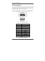
TABLE OF CONTENTS
Introduction
Special Features............................................................................2
Package Contents .........................................................................2
Design Features
Repeater Functions .......................................................................3
Jabber Lock-up Protection.............................................................3
Fragment Extension.......................................................................3
Collision-Handling..........................................................................3
Automatic Partitioning/Reconnection.............................................4
Link Test ........................................................................................4
Hardware Installation
Front Panel ....................................................................................5
Power LED ....................................................................5
Utilization LEDs .............................................................5
Collision LEDs ...............................................................5
AUI LED.........................................................................6
BNC LED .......................................................................6
UTP Port LEDs ..............................................................6
Cascade Switch.............................................................7
Rear Panel.....................................................................................8
Power Switch.................................................................8
KNE24TP/RS User’s Guide - Rev. A01
Kingston Technology Company
ii
AC Power Connector .................................................... 8
AUI Port ........................................................................ 8
BNC Port....................................................................... 8
Stacking Ports............................................................... 8
Stacking EtheRx Hubs .................................................................. 9
Network Configurations
Ethernet 5-4-3 Rule..................................................................... 10
Ethernet Star Network................................................................. 10
Linear Bus Network..................................................................... 11
Horizontal Cascading.................................................................. 11
Cascading with Stacked Hubs .................................................... 12
Appendices
Appendix A
Pin Assignments................................................... 14
Appendix B
Cabling Guidelines ............................................... 16
Appendix C
Specifications ....................................................... 19
Appendix D
Mounting Templates ............................................. 21
Appendix E
Product Warranties and Notices........................... 22
Limited Warranty Statement ....................................... 22
Duration of Warranty................................................... 23
Free Technical Support .............................................. 23
Disclaimers ................................................................. 23
FCC Certification / CE Notice ..................................... 24
Kingston Technology Company
KNE24TP/RS User’s Guide - Rev. A01
General Information
1
Introduction
Intended Audience: This manual assumes that the user has a general working
knowledge of networking principles and architecture and is familiar with
network systems in general.
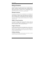
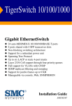
Congratulations on the purchase of your new Kingston Pro-Series® 19-inch
rack-mount, stackable 10BASE-T Ethernet Hub. There are two models: the
KNE16TP/RS and KNE24TP/RS, 16-Port and 24-Port Ethernet hubs,
respectively. The Pro-Series models offer several new enhancements. The
Stack-n-Play® feature allows for easy installation without the need to configure
ID switches. The Hot-Stack® feature allows adding new hubs without powering
down. The Smart Monitor® feature offers network traffic monitoring through a
bar-graph LED display.
The EtheRx hubs provide sixteen (16) or twenty-four (24) UTP (Unshielded
Twisted-Pair) ports for 10BASE-T Ethernet connections, one BNC port for
10BASE2 thin Ethernet connection, and one AUI (Attachment Unit Interface)
port for either 10BASE2 Cheapernet, 10BASE5 thick Ethernet, 10BASE-T,
10BASE-FL, or FOIRL (Fiber Optic Inter Repeater Link) segment using a
proper external transceiver. The last UTP port (i.e., Port 16 or Port 24) uses a
cascade switch to support both crossover and straight-thru cable wiring for
uplinking to another 10BASE-T hub.
The EtheRx models can also be stacked up to five hubs using the stacking
cable (provided) expanding your network to a maximum of 80 or 120 UTP
ports (depending on the model) as a single repeater unit. The EtheRx hubs can
be used on desktop or 19-inch rack-mount installations (mounting hardware
included). The front panel includes pull handles for rack-mounting and a
variety of diagnostic LEDs including: Power, five levels of Utilization and
Collision status, AUI, BNC, and UTP port LEDs which display Link, Activity
and Partition status.
KNE16TP/RS
Stackable Ethernet Hub
1
2
3
4
5
6
7
8
9
10
11
12
13
14
15
16
LINK / ACT / PARTITION
1
UTIL %
PWR
2
3
4
5
6
7
CABLE TYPE
8
AUI BNC
9 10 11 12
COLL %
13 14 15 16
KNE24TP/RS
Stackable Ethernet Hub
UTIL %
PWR
1
2
3
4
5
6
7
8
9
10
11
12
13
14
15
16
17
18
19
20
21
22
23
24
LINK / ACT / PARTITION
1
2
3
4
8
9 10 11 12
17 18 19 20
5
6
7
21 22 23 24
CASCADE
CABLE TYPE
AUI BNC
COLL %
13 14 15 16
CASCADE
Models KNE16TP/RS and KNE24TP/RS
KNE24TP/RS User’s Guide - Rev. A01
Kingston Technology Company
2
General Information
Special Features
•
•
•
•
•
•
•
•
•
•
•
•
•
•
•
•
Stack-n-Play™ ports connect up to five EtheRx hubs as a
single repeater unit
Hot-Stack™ additional hubs without powering down
Smart Monitor™ bar-graph LEDs for network traffic monitoring
16 or 24 UTP ports for 10BASE-T connections
1 BNC port for 10BASE2 thin Ethernet connection
1 AUI port for backbone or mixed media connection
Cascade switch on last UTP port
UTP Link, Activity, and Partition Status LEDs for easy troubleshooting
BNC Activity and Partition LED
AUI Activity and Partition LED
5 Utilization LEDs to monitor network traffic
5 Collision LEDs to monitor data collision
Automatic partition and reconnection
Internal auto-sensing power supply operating at 110VAC or 240VAC
Complies with IEEE 802.3 and 802.3i Ethernet standards
19-inch rack mountable (mounting kit included)
Package Contents
Your EtheRx package should contain the following items:
ο
ο
ο
ο
ο
KNE16TP/RS or KNE24TP/RS Ethernet Hub
5.5” shielded stacking cable
AC power cord
BNC T-connector
Mounting kit includes:
(2) Angle brackets
(8) Bracket mounting screws
(4) 10/32” Rack-mount screws
(4) Rubber Feet
ο
User's Guide
If any of the items are missing or damaged, please contact your Kingston
dealer for a replacement. Be sure the items you receive are genuine Kingston
Technology products. If the Kingston name and logo are not on the front panel
of your unit, it’s not a genuine Kingston product.
Kingston Technology Company
KNE24TP/RS User’s Guide - Rev. A01
Design Features
3
Design Features
The EtheRx Pro-Series hubs comply with the full set of repeater functions as
defined by IEEE802.3 CSMA/CD and IEEE 802.3i 10BASE-T Ethernet
standard. These functions include all Repeater Functions, Signal Regeneration,
Jabber Lockup Protection, Fragment Extension, Collision-Handling, Auto
Partitioning/Reconnection and Link Test. These functions are usually
transparent to all network activities and are summarized below.
Repeater Functions
If any single port senses the start of a valid packet on its receiving line, the
EtheRx hub will re-transmit the received data to all other ports on the network.
The re-transmission of packets complies with the IEEE 802.3 specification in
terms of preamble structure, voltage amplitude, and timing characteristics.
These timing regenerations prevent cumulative signal loss, jitter, and distortion
caused by the network cabling, and allow the EtheRx hubs to be cascaded to
other Ethernet hubs.
Jabber Lock-up Protection
The EtheRx hubs implement a built-in jabber protection scheme to ensure that
the network is not disabled due to transmission of excessively long data
packets. This protection scheme will automatically interrupt the reception of
abnormally long streams of data to prevent jabber lock-up.
Fragment Extension
If the total packet length received by the EtheRx hub is less than 96 bits,
including preamble, then the hub will automatically extend the repeated packet
length to 96 bits by appending a jam sequence to the original fragment. The
extension of a fragmented packet allows the reliable detection of a collision by
all stations attached to the network.
Collision-Handling
The EtheRx hubs will perform collision detection and respond to collision
conditions as defined in the IEEE 802.3 specifications.
KNE24TP/RS User’s Guide - Rev. A01
Kingston Technology Company
4
Design Features
Automatic Partitioning/Reconnection
If any of the ports on the EtheRx hub experience excessive numbers of
consecutive collisions, duration collisions, or faulty conditions, that particular
port can be partitioned. Once partitioned, the hub will continue to monitor that
port. If the error conditions have been corrected or a good data packet is
transmitted or received without incurring a collision, the hub will automatically
reconnect that port to the network.
Link Test
For UTP port connections, the EtheRx hub implements the link integrity test
function as specified in the IEEE 802.3i 10BASE-T standard. The hub will
transmit link test pulses to any UTP port after that port’s transmitter is inactive
for a range of 8ms to 17ms. These pulses are sent to confirm that a valid
connection exists between each UTP port on the hub and its attached device.
Kingston Technology Company
KNE24TP/RS User’s Guide - Rev. A01
Hardware Installation
5
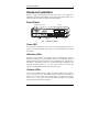
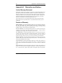
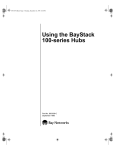
Hardware Installation
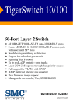
Before you begin installing network cables, please take a few moments to
familiarize yourself with the EtheRx 16-Port and 24-Port Ethernet Hubs. The
functions on the front and rear panels are illustrated below.
Front Panel
Utilization LEDs
Collision LEDs
UTP Ports
KNE16TP/RS
Pro-Series Ethernet Hub
2
3
4
5
6
7
2
3
4
5
6
7
8
9
10
11
12
13
14
15
16
CABLE TYPE
8
AUI BNC
9 10 11 12
COLL %
13 14 15 16
KNE24TP/RS
Pro-Series Ethernet Hub
1
2
3
4
5
6
7
8
9
10
11
12
13
14
15
16
17
18
19
20
21
22
23
24
LINK / ACT / PARTITION
1
UTIL %
PWR
2
3
4
8
9 10 11 12
17 18 19 20
5
6
7
21 22 23 24
CASCADE
CABLE TYPE
AUI BNC
13 14 15 16
COLL %
Power
LED
1
LINK / ACT / PARTITION
1
UTIL %
PWR
AUI
LED
BNC
LED
Link /Activity / Partition
LEDs
UTP Ports
CASCADE
Cascade Switch
(MDI-X or MDI)
Fig. 1. Hub Front Panels
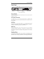
Power LED
The green LED indicates the power status. The LED will light when the AC
power cord is connected from a power source to the hub and the power switch
is turned on.
Utilization LEDs
Kingston’s Smart Monitor™ bar-graph LEDs for utilization and collision
provide easy monitoring of network traffic. There are five Utilization LEDs to
display the amount of network traffic in five percentage levels. The amount of
data traffic is measured in frames per second (FPS), then calculated into the
following percentage forms: 1%, 7%, 15%, 30%, and 60%. The LEDs will
light in a bar-graph fashion based on the network activity.
Collision LEDs
There are five Collision LEDs to display the amount of data packet collisions
in five percentage levels. The amount of data collisions is measured in
collisions per second (CPS), then calculated into the following percentage
levels: 1%, 7%, 15%, 30%, and 60%. The LEDs will light in a bar-graph
fashion based on the amount of collisions.
KNE24TP/RS User’s Guide - Rev. A01
Kingston Technology Company
6
Hardware Installation
AUI LED
The two-color LED displays two states of operation for the Activity and
Partition status on the AUI port. When data is received, the LED will flash
green. If the port has been partitioned due to excessive collision or other faulty
condition, it will display solid red.
Note: Upon power up, the AUI port LED will not be lit unless a transceiver is
attached to the port and there is activity.
BNC LED
The two-color LED displays the Activity and Partition status on the BNC port.
When data is received, the LED will flash green. If the port is partitioned due
to excessive collision or other faulty condition, it will display solid red.
Note: Upon power up, if the BNC port has no cable attached or is not properly
terminated at both ends, the LED will display red to show the port has been
partitioned. Upon receipt of good packets, the LED will automatically change
from red to green indicating that the port is functioning properly.
UTP Port LEDs
The sixteen or twenty-four UTP Port LEDs offer condition status for Link,
Activity, and Partition. If a good link is established on any given port, the
green LED will be continuously lit, indicating a valid network connection
between the network node and the hub. When data is received, the LED will
flash green. If the port is partitioned, the LED will display solid red.
If the LED does not display solid green indicating a good link, check the
following:
1.
Make sure the power is turned on for both the PC
and EtheRx Hub. The power LED should be lit.
2.
Verify the network drivers have been loaded from the PC. Some
adapters require the drivers to be loaded to establish a proper link.
3.
Make sure the correct cable type is selected.
4.
Make sure the cable is wired properly and connected on both ends.
5.
If steps 1, 2, 3, and 4 are correct, the cable may be defective or
not wired correctly. Replace the cable and try again. Please
refer to Appendix A for pin assignments and Appendix B for
cabling guidelines.
Kingston Technology Company
KNE24TP/RS User’s Guide - Rev. A01
Hardware Installation
7
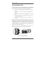
Cascade Switch
The cascade switch provides cable wiring flexibility on the last UTP Port (i.e.,
Port 16 or Port 24) for connecting to a workstation or cascading to another hub.
By default, the last UTP port is set to “Crossover” (left side) as a standard,
internally-crossed port, or MDI-X port. Depending on the wiring of your UTP
cable (normally “Straight-Thru”), the port is used to connect a workstation.
For cascading to another hub using a straight-thru cable, move the cascade
switch to “Straight-Thru” (right side). If a crossover UTP cable is used to
cascade to another hub, leave the cascade switch in the “Crossover” position.
Using a Straight-Thru Cable
"Crossover"
Default Position
CABLE TYPE
24
for NIC/Router
connections
(MDI-X to MDI)
CASCADE
CABLE TYPE
24
"Straight-Thru"
Position
for hub to hub
cascading
(MDI to MDI-X)
CASCADE
Using a Crossover Cable
"Crossover"
Default Position
CABLE TYPE
24
for hub to hub
cascading
(MDI-X to MDI-X)
CASCADE
CABLE TYPE
24
"Straight-Thru"
Position
for NIC/Router
connections
(MDI to MDI)
CASCADE
MDI (Media Dependent Interface) is the standard that defines the mechanical
and electrical configuration of a UTP port. For any two devices to
communicate on the network, the transmitter of one device must be connected
to the receiver of the other device. This can be achieved by using a crossover
cable, or by using one MDI-X port that implements the cross-over internally.
Switch
Position
Port
Config
For Connection to
Another Hub Port (MDI-X)
For Connection to a Network
Adapter or Router (MDI)
MDI-X
Use Crossover cable
Use Straight-Thru cable
MDI
Use Straight-Thru cable
Use Crossover cable
Table 1. Switch Position and Cable Types
KNE24TP/RS User’s Guide - Rev. A01
Kingston Technology Company
8
Hardware Installation
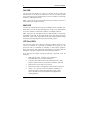
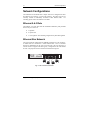
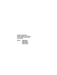
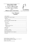
Rear Panel
100-240VAC 50-60HZ 1A
STACK-IN STACK-OUT
PORT #16 OR PORT #24
CASCADE CONFIGURATION
For cascading to another MDI-X
hub port using straight-thru cable.
For connection to workstation NIC
using cross-over cable.
For cascading to another MDI-X
hub port using cross-over cable.
For connection to workstation NIC
using straight-thru cable.
Stacking Ports
BNC
EXTERNAL TRANSCEIVER
( SQE JUMPER DISABLED)
1% Green
7% Green
UTILIZATION % - Bar graph indication
(in percentage) of the traffic rate in
ON
UTIL % 15% Green reference to the 10 Mbps Ethernet
30% Amber bandwidth.
60% Orange
1% Amber COLLISION % - Bargraph indication
7% Amber (in percentage) of the packet collision
COLL % 15% Amber rate in the network.
AUI
BNC Port
AUI Port
30% Amber
60% Red
OFF
AC Power Power
Connector Switch
Fig. 2. Hub Rear Panel
Power Switch
The power switch toggles power on and off to the unit. The switch can also be
used to reset the hub.
AC Power Connector
The EtheRx hubs use an auto-sensing 100VAC-240VAC, 50/60Hz internal
power supply. Connect the AC power cord from the rear of the unit to an AC
electrical outlet.
AUI Port
The AUI port is a 15-pin D-sub connector. It is a general purpose port for
backbone or mixed media connections for 10BASE2, 10BASE5, 10BASE-T,
or FOIRL connections using a proper external transceiver.
BNC Port
This port is labeled BNC, and has a built-in transceiver for direct 10BASE2
connection using thin coaxial cable. Use RG-58 A/U or RG-58 C/U type
cable. Refer to Appendix B for 10BASE2 cabling guidelines when connecting
to this port.
Stacking Ports
The two ports are labeled“Stack-In” and “Stack-Out” for stacking up to five
(5) EtheRx Pro-Series hubs in any combination of 16-Port and 24-Port models.
Refer to the section, “Stacking EtheRx Hubs” on the next page for instructions.
Kingston Technology Company
KNE24TP/RS User’s Guide - Rev. A01
Hardware Installation
9
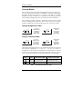
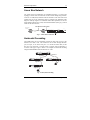
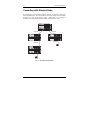
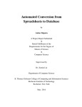
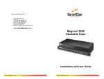
Stacking EtheRx Hubs
The EtheRx hubs use stacking ports located on the rear panel to stack up to five
hubs in any combination of 16-Port KNE16TP/RS and 24-Port KNE24TP/RS
models. Follow the directions below to stack up to five hubs together:
1.
Locate the 5.5” shielded stacking cable included with your package
contents.
2.
Plug one end of the cable into the port labeled, “Stack-Out” on the
first hub.
3.
Plug the other end of the cable into the “Stack-In” port on the second
hub.
4.
Connect the AC power cord to each hub, then flip the power switch
to turn on power to the unit.
5.
Repeat the process to stack additional hubs up to a maximum of five
(5) hubs.
Kingston’s Stack-n-Play™ feature offers greater scalabilty to add UTP ports
without the need to configure ID or termination switches. EtheRx hubs when
stacked together are recognized as a single repeater unit on the network. By
stacking hubs together, you can expand the total number of UTP port
connections from 16 to 80 or from 24 to 120 UTP ports, depending on the
model. A maximum of five (5) Pro-Series hubs can be stacked in any
combination of 16 and 24-Port hub models.
Kingston’s Hot-Stack™ feature allows the addition of new hubs to the top or
bottom of a stack without the need to power down the existing hubs.
STACK-IN STACK-OUT
PORT #16 OR P
CASCADE CONFIG
For cascading to
hub port using s
For connection t
using cross-ove
For cascading to
hub port using c
For connection t
using straight-th
100-240VAC 50-60HZ 1A
STACK-IN STACK-OUT
PORT #16 OR P
CASCADE CONFIG
For cascading to
hub port using s
For connection t
using cross-ove
For cascading to
hub port using c
For connection t
using straight-th
STACK-IN STACK-OUT
PORT #16 OR PORT #24
CASCADE CONFIGURATION
For cascading to another MDI-X
hub port using straight-thru cable.
For connection to workstation NIC
using cross-over cable.
For cascading to another MDI-X
hub port using cross-over cable.
For connection to workstation NIC
using straight-thru cable.
BNC
EXTERNAL TRANSCEIVER
( SQE JUMPER DISABLED)
BNC
EXTERNAL TRANSCEIVER
( SQE JUMPER DISABLED)
1% Green
7% Green
UTILIZATION % - Bar graph indication
(in percentage) of the traffic rate in
ON
UTIL % 15% Green reference to the 10 Mbps Ethernet
30% Amber bandwidth.
60% Orange
1% Amber COLLISION % - Bargraph indication
7% Amber (in percentage) of the packet collision
COLL % 15% Amber rate in the network.
AUI
30% Amber
60% Red
OFF
100-240VAC 50-60HZ 1A
STACK-IN STACK-OUT
PORT #16 OR PORT #24
CASCADE CONFIGURATION
For cascading to another MDI-X
hub port using straight-thru cable.
For connection to workstation NIC
using cross-over cable.
For cascading to another MDI-X
hub port using cross-over cable.
For connection to workstation NIC
using straight-thru cable.
BNC
EXTERNAL TRANSCEIVER
( SQE JUMPER DISABLED)
BNC
EXTERNAL TRANSCEIVER
( SQE JUMPER DISABLED)
1% Green
7% Green
UTILIZATION % - Bar graph indication
(in percentage) of the traffic rate in
ON
UTIL % 15% Green reference to the 10 Mbps Ethernet
30% Amber bandwidth.
60% Orange
1% Amber COLLISION % - Bargraph indication
7% Amber (in percentage) of the packet collision
COLL % 15% Amber rate in the network.
AUI
30% Amber
60% Red
Stack
up to
5 hubs
maximum
OFF
100-240VAC 50-60HZ 1A
STACK-IN STACK-OUT
STACK-IN STACK-OUT
PORT #16 OR P
CASCADE CONFIG
For cascading to
hub port using s
For connection t
using cross-ove
For cascading to
hub port using c
For connection t
using straight-th
PORT #16 OR PORT #24
CASCADE CONFIGURATION
For cascading to another MDI-X
hub port using straight-thru cable.
For connection to workstation NIC
using cross-over cable.
For cascading to another MDI-X
hub port using cross-over cable.
For connection to workstation NIC
using straight-thru cable.
1% Green
7% Green
UTILIZATION % - Bar graph indication
(in percentage) of the traffic rate in
ON
UTIL % 15% Green reference to the 10 Mbps Ethernet
30% Amber bandwidth.
60% Orange
1% Amber COLLISION % - Bargraph indication
7% Amber (in percentage) of the packet collision
COLL % 15% Amber rate in the network.
AUI
30% Amber
60% Red
OFF
100-240VAC 50-60HZ 1A
STACK-IN STACK-OUT
PORT #16 OR PORT #24
CASCADE CONFIGURATION
For cascading to another MDI-X
hub port using straight-thru cable.
For connection to workstation NIC
using cross-over cable.
For cascading to another MDI-X
hub port using cross-over cable.
For connection to workstation NIC
using straight-thru cable.
BNC
EXTERNAL TRANSCEIVER
( SQE JUMPER DISABLED)
1% Green
7% Green
UTILIZATION % - Bar graph indication
(in percentage) of the traffic rate in
ON
UTIL % 15% Green reference to the 10 Mbps Ethernet
30% Amber bandwidth.
60% Orange
1% Amber COLLISION % - Bargraph indication
7% Amber (in percentage) of the packet collision
COLL % 15% Amber rate in the network.
AUI
30% Amber
60% Red
OFF
Fig. 3. Stacking Additional Hubs
KNE24TP/RS User’s Guide - Rev. A01
Kingston Technology Company
10
Network Configurations
Network Configurations
The installation of the EtheRx hub is simple and can be configured for either
the Ethernet Star topology or Linear Bus topology. The hubs may also be
vertically stacked or horizontally cascaded to other Ethernet hubs. For
cascading, please observe the Ethernet 5-4-3 Rule.
Ethernet 5-4-3 Rule
The Ethernet 5-4-3 rule states that the maximum transmission path permitted
between any two stations is:
•
5 segments
•
4 repeater sets
•
3 coax segments. The remaining 2 segments may be linked segments
Ethernet Star Network
The typical network configuration for 10BASE-T Ethernet is a Star Topology,
in which nodes are connected to a central Ethernet hub. Since a Crossover
function is implemented on all ports (except the last UTP port which uses a
cascade switch to support both cable types), a straight-thru UTP cable should
be used. The physical network connection is illustrated in Figure 4.
KNE24TP/RS
Pro-Series Ethernet Hub
UTIL %
PWR
1
2
3
4
5
6
7
8
9
10
11
12
13
14
15
16
17
18
19
20
21
22
23
24
LINK / ACT / PARTITION
1
2
3
4
8
9 10 11 12
17 18 19 20
5
6
7
21 22 23 24
CABLE TYPE
AUI BNC
COLL %
13 14 15 16
CASCADE
Fig. 4. Star Network Connection
Kingston Technology Company
KNE24TP/RS User’s Guide - Rev. A01
Network Configurations
11
Linear Bus Network
The typical network configuration for 10BASE2 networks is a Linear Bus
topology in which nodes are connected via thin coaxial cabling using the BNC
connector. A 50Ω (Ohm) terminator must be attached to each end of the trunk
segment and one of the terminators must be grounded. The maximum cable
length is 185M per segment. To minimize cable-related problems, do not mix
single filament (black PVC jacket) with stranded filament (DEC grey) coaxial
cables on the same network.
Thin Ethernet Coax Cable
50-Ohm Terminator
on last Node
100-240VAC 50-60HZ 1A
PORT #16 OR PORT #24
CASCADE CONFIGURATION
STACK-IN STACK-OUT
EXTERNAL TRANSCEIVER
( SQE JUMPER DISABLED)
BNC
For cascading to another MDI-X
hub port using straight-thru cable.
For connection to workstation NIC
using cross-over cable.
For cascading to another MDI-X
hub port using cross-over cable.
For connection to workstation NIC
using straight-thru cable.
es
Up to 30 Nod
UTIL %
COLL %
AUI
1% Green UTILIZATION % - Bar graph indication
7% Green (in percentage) of the traffic rate in
15% Green reference to the 10 Mbps Ethernet
30% Amber bandwidth.
60% Orange
1% Amber COLLISION % - Bargraph indication
7% Amber (in percentage) of the packet collision
15% Amber rate in the network.
30% Amber
60% Red
ON
OFF
50-Ohm Grounded
Terminator
Fig. 5. Linear Bus Connection
Horizontal Cascading
The EtheRx hubs can be horizontally cascaded to other hubs as long as the
Ethernet 5-4-3 Rule is met. This connection can be made through the BNC
port, AUI port, or one of the UTP ports. To cascade to another hub, use the
last UTP port which has a cascade switch to support either straight-thru or
crossover cable types. Figure 6 below is an example of horizontal cascading
using the KNE24TP/RS under the Ethernet 5-4-3 rule.
KNE24TP/RS
Slick-Stack Ethernet Hub
1
2
3
4
5
6
7
8
9
10
11
12
13
14
15
16
17
18
19
20
21
22
23
24
LINK / ACT / PARTITION
1
UTIL %
PWR
2
3
4
8
9 10 11 12
17 18 19 20
5
6
7
21 22 23 24
CABLE TYPE
AUI BNC
13 14 15 16
COLL %
CASCADE
Segment 4
Segment 3
KNE24TP/RS
Slick-Stack Ethernet Hub
UTIL %
PWR
1
2
2
3
3
LINK / ACT / PARTITION
4
5
6
7
4
8
9 10 11 12
17 18 19 20
21 22 23 24
1
2
13
14
5
3
4
15
16
6
7
5
8
6
7
8
9
10
11
12
19
20
21
22
23
24
8
KNE24TP/RS
CABLE TYPE
PWR
13 14 15 16
17
18
KNE24TP/RS
UTIL %
PWR
2
3
4
8
9 10 11 12
17 18 19 20
5
6
7
21 22 23 24
2
3
4
13 14 15 16
8
9 10 11 12
17 18 19 20
5
6
7
21 22 23 24
2
3
4
5
6
7
8
9
10
11
12
14
15
16
17
18
19
20
21
22
23
24
CABLE TYPE
Segment 5
1
2
3
4
5
6
7
8
9
10
11
12
13
14
15
16
17
18
19
20
21
22
23
24
LINK / ACT / PARTITION
1
1
13
LINK / ACT / PARTITION
1
AUI BNC
COLL %
CASCADE
Segment 2
Slick-Stack Ethernet Hub
Slick-Stack Ethernet Hub
UTIL %
AUI BNC
COLL %
CASCADE
100M max.
per segment
CABLE TYPE
AUI BNC
COLL %
13 14 15 16
CASCADE
Segment 1
Fig. 6. Horizontal Cascading
KNE24TP/RS User’s Guide - Rev. A01
Kingston Technology Company
12
Network Configurations
Cascading with Stacked Hubs
By stacking up to five Pro-Series hubs per segment, the number of UTP ports
increases dramatically. The total number of UTP ports changes from 90 (shown
in Figure 6) to 474 (shown below). Figure 7 listed below is an example of
horizontal cascading with stacked hubs under the Ethernet 5-4-3 rule.
KNE24TP/RS
Slick-Stack Ethernet Hub
UTIL %
PWR
1
2
3
4
5
6
7
8
9
10
11
12
13
14
15
16
17
18
19
20
21
22
23
24
LINK / ACT / PARTITION
1
2
3
4
8
9 10 11 12
17 18 19 20
5
6
7
21 22 23 24
CABLE TYPE
AUI BNC
13 14 15 16
COLL %
KNE24TP/RS
Slick-Stack Ethernet Hub
UTIL %
PWR
1
2
3
4
5
6
7
8
9
10
11
12
13
14
15
16
17
18
19
20
21
22
23
24
LINK / ACT / PARTITION
1
2
3
4
8
9 10 11 12
17 18 19 20
5
6
7
21 22 23 24
CASCADE
CABLE TYPE
AUI BNC
13 14 15 16
COLL %
KNE24TP/RS
Slick-Stack Ethernet Hub
UTIL %
PWR
1
2
3
4
5
6
7
8
9
10
11
12
13
14
15
16
17
18
19
20
21
22
23
24
1
2
3
4
5
6
7
8
9
10
11
12
13
14
15
16
17
18
19
20
21
22
23
24
1
2
3
4
5
6
7
8
9
10
11
12
13
14
15
16
17
18
19
20
21
22
23
24
LINK / ACT / PARTITION
1
2
3
4
8
9 10 11 12
17 18 19 20
5
6
7
21 22 23 24
CASCADE
CABLE TYPE
AUI BNC
13 14 15 16
COLL %
KNE24TP/RS
Slick-Stack Ethernet Hub
UTIL %
PWR
LINK / ACT / PARTITION
1
2
3
4
8
9 10 11 12
17 18 19 20
5
6
7
21 22 23 24
CASCADE
CABLE TYPE
AUI BNC
13 14 15 16
COLL %
KNE24TP/RS
Slick-Stack Ethernet Hub
UTIL %
PWR
LINK / ACT / PARTITION
1
2
3
4
8
9 10 11 12
17 18 19 20
5
6
7
21 22 23 24
CASCADE
CABLE TYPE
AUI BNC
COLL %
13 14 15 16
CASCADE
Segment 3
KNE24TP/RS
Slick-Stack Ethernet Hub
UTIL %
PWR
Segment 4
1
2
3
4
5
6
7
8
9
10
11
12
13
14
15
16
17
18
19
20
21
22
23
24
1
2
3
4
5
6
7
8
9
10
11
12
LINK / ACT / PARTITION
1
2
3
4
8
9 10 11 12
17 18 19 20
5
6
7
21 22 23 24
KNE24TP/RS
CABLE TYPE
PWR
13 14 15 16
KNE24TP/RS
UTIL %
PWR
LINK / ACT / PARTITION
1
2
3
4
8
9 10 11 12
17 18 19 20
5
6
7
21 22 23 24
KNE24TP/RS
Slick-Stack Ethernet Hub
UTIL %
PWR
14
15
16
17
18
19
20
21
22
23
24
1
2
3
4
5
6
7
8
9
10
11
12
13
14
15
16
17
18
19
20
21
22
23
24
1
2
3
4
5
6
7
8
9
10
11
12
13
14
15
16
17
18
19
20
21
22
23
24
LINK / ACT / PARTITION
1
2
3
4
8
9 10 11 12
17 18 19 20
5
6
7
21 22 23 24
KNE24TP/RS
Slick-Stack Ethernet Hub
UTIL %
PWR
CABLE TYPE
2
3
4
8
9 10 11 12
17 18 19 20
5
6
7
21 22 23 24
UTIL %
PWR
2
3
4
8
9 10 11 12
17 18 19 20
5
6
7
21 22 23 24
1
2
3
4
5
6
7
8
9
10
11
12
14
15
16
17
18
19
20
21
22
23
24
Slick-Stack Ethernet Hub
2
3
4
8
9 10 11 12
17 18 19 20
5
6
7
21 22 23 24
6
7
7
8
9 10 11 12
21 22 23 24
2
3
4
8
9 10 11 12
17 18 19 20
5
6
7
21 22 23 24
2
3
4
5
6
7
8
9
10
11
12
14
15
16
17
18
19
20
21
22
23
24
1
2
3
4
5
6
7
8
9
10
11
12
13
14
15
16
17
18
19
20
21
22
23
24
1
2
3
4
5
6
7
8
9
10
11
12
13
14
15
16
17
18
19
20
21
22
23
24
1
2
3
4
5
6
7
8
9
10
11
12
13
14
15
16
17
18
19
20
21
22
23
24
CABLE TYPE
CASCADE
CABLE TYPE
CASCADE
CABLE TYPE
LINK / ACT / PARTITION
1
2
3
4
13 14 15 16
8
9 10 11 12
17 18 19 20
5
6
7
21 22 23 24
KNE24TP/RS
CABLE TYPE
Slick-Stack Ethernet Hub
UTIL %
CASCADE
CABLE TYPE
1
2
3
4
5
6
7
8
9
10
11
12
13
14
15
16
17
18
19
20
21
22
23
24
LINK / ACT / PARTITION
1
2
3
4
8
9 10 11 12
17 18 19 20
5
6
7
21 22 23 24
CASCADE
CABLE TYPE
AUI BNC
COLL %
13 14 15 16
CASCADE
CASCADE
Segment 5
1
2
3
4
5
6
7
8
9
10
11
12
13
14
15
16
17
18
19
20
21
22
23
24
1
2
3
4
5
6
7
8
9
10
11
12
13
14
15
16
17
18
19
20
21
22
23
24
1
2
3
4
5
6
7
8
9
10
11
12
13
14
15
16
17
18
19
20
21
22
23
24
LINK / ACT / PARTITION
1
6
AUI BNC
COLL %
PWR
KNE24TP/RS
UTIL %
PWR
9 10 11 12
21 22 23 24
5
CASCADE
Segment 2
Slick-Stack Ethernet Hub
5
17 18 19 20
LINK / ACT / PARTITION
1
13 14 15 16
UTIL %
13
8
17 18 19 20
KNE24TP/RS
CABLE TYPE
LINK / ACT / PARTITION
1
13 14 15 16
4
AUI BNC
COLL %
AUI BNC
COLL %
4
CASCADE
PWR
KNE24TP/RS
Slick-Stack Ethernet Hub
Slick-Stack Ethernet Hub
UTIL %
LINK / ACT / PARTITION
1
13 14 15 16
3
KNE24TP/RS
AUI BNC
COLL %
2
13 14 15 16
CASCADE
PWR
13 14 15 16
3
LINK / ACT / PARTITION
1
AUI BNC
COLL %
AUI BNC
COLL %
Slick-Stack Ethernet Hub
UTIL %
13
1
13
LINK / ACT / PARTITION
2
13 14 15 16
KNE24TP/RS
CABLE TYPE
PWR
13 14 15 16
1
AUI BNC
COLL %
CASCADE
AUI BNC
COLL %
Slick-Stack Ethernet Hub
UTIL %
AUI BNC
COLL %
Slick-Stack Ethernet Hub
CABLE TYPE
AUI BNC
13 14 15 16
COLL %
KNE24TP/RS
Slick-Stack Ethernet Hub
UTIL %
PWR
LINK / ACT / PARTITION
1
2
3
4
5
6
7
8
9 10 11 12
17 18 19 20
21 22 23 24
CASCADE
CABLE TYPE
AUI BNC
13 14 15 16
COLL %
KNE24TP/RS
Slick-Stack Ethernet Hub
UTIL %
PWR
LINK / ACT / PARTITION
1
2
3
4
8
9 10 11 12
17 18 19 20
5
6
7
21 22 23 24
CASCADE
CABLE TYPE
AUI BNC
13 14 15 16
COLL %
KNE24TP/RS
Slick-Stack Ethernet Hub
UTIL %
PWR
1
2
3
4
5
6
7
8
9
10
11
12
13
14
15
16
17
18
19
20
21
22
23
24
LINK / ACT / PARTITION
1
2
3
4
8
9 10 11 12
17 18 19 20
5
6
7
21 22 23 24
CASCADE
CABLE TYPE
AUI BNC
13 14 15 16
COLL %
KNE24TP/RS
Slick-Stack Ethernet Hub
UTIL %
PWR
1
2
3
4
5
6
7
8
9
10
11
12
13
14
15
16
17
18
19
20
21
22
23
24
LINK / ACT / PARTITION
1
2
3
4
8
9 10 11 12
17 18 19 20
5
6
7
21 22 23 24
CASCADE
CABLE TYPE
AUI BNC
COLL %
13 14 15 16
CASCADE
Segment 1
Fig. 7. Cascading Stacked Hubs
Kingston Technology Company
KNE24TP/RS User’s Guide - Rev. A01
13
Appendices
KNE24TP/RS User’s Guide - Rev. A01
Kingston Technology Company
14
Appendix A Pin Assignments
Appendix A
Pin Assignments
UTP Pin Assignments
UTP Ports use RJ-45 Unshielded Twisted Pair (UTP) cabling. Cable Pin
Numbers and Pin Wiring Assignments are listed below in Figure A-1 and Table
A-2, respectively. Twisted-Pair cables can be wired with either Straight-Thru
or Crossover pin assignments. Both wiring schemes are mentioned in
"Appendix B Cabling Guidelines" for reference in creating a twisted-pair cable.
1
2
3
4
5
6
7
9
10
11
12
13
14
15
1 2 3 4 5 6 7 8
Fig. A-1 RJ-45 Connector Pin Numbers
Pin Number
1
MDI-X /
MDI /
Receive Data +
Transmit Data +
2
Receive Data -
Transmit Data -
3
Transmit Data +
Receive Data +
4,5
Not Used
Not Used
6
Transmit Data -
Receive Data -
7,8
Not Used
Not Used
Table A-1 UTP Pin Assignments
Kingston Technology Company
KNE24TP/RS User’s Guide - Rev. A01
Appendix A
Pin Assignments
15
AUI Pin Assignments
The AUI port, labeled AUI on the rear panel of the hub, is a general purpose
port for backbone or mixed media connection using: 10BASE2 thin coaxial,
10BASE5 thick coaxial, 10BASE-T UTP, 10BASE-FL and Fiber Optic InterRepeater Link (FOIRL), using an external transceiver.
When attaching a 10BASE-T hub to a Thinnet or Thicknet network through the
AUI port, the SQE jumper must be disabled on the attaching transceiver.
EXTERNAL TRANSCEIVER
( SQE JUMPER DISABLED )
AUI
8 7 6 5 4 3 2 1
15 14 13 12 11 10 9
Fig. A-3 AUI Connector on Rear Panel
Pin Number
1
2
3
4
5
6
7
8
9
10
11
12
13
14
15
Function
Collision Shield
Collision +
Transmit +
Receive Shield
Receive +
Power Return
Not Used
Circuit Shield
Collision Transmit Transmit Shield
Receive Voltage +
Voltage Shield
Not Used
Table A-4 AUI Pin Assignments
KNE24TP/RS User’s Guide - Rev. A01
Kingston Technology Company
16
Appendix B
Appendix B
Cabling Guidelines
Cabling Guidelines
Cable Types
When connecting network cables, the following table shows appropriate
networking guidelines associated with each cable type.
10BASE5
10BASE2
10BASE-T
Cable Type:
Ethernet Standard:
RG-11
RG-58/U
Max. Segment
Length:
Max. Number of
Nodes per Segment:
Connector:
500M
(1640ft)
185M
(600ft)
UTP CAT
3, 4 or 5
100M
(328ft)
100
15-pin D-Sub
30
BNC
1024
RJ-45
Linear Bus
Linear Bus
Star
Network Topology:
Table B-1 Network Cable Guidelines
UTP Cable Wiring
10BASE-T unshielded twisted-pair cables can be wired as "Straight-Thru" or,
in some cases, "Crossover" depending on the application. For workstations
connected to a hub, use "Straight-Thru' wiring illustrated below in Table B-2.
In some instances (e.g. cascading from one hub to another), you may use
"Crossover" wiring illustrated below in Table B-3.
"Straight-Thru"
Cable Wiring
Crossover”
Cable Wiring
Pin Number
Pin Number
Pin Number
Pin Number
1 (TRX +)
1 (TRX +)
1 (TRX +)
3 (RCV +)
2 (TRX -)
2 (TRX -)
2 (TRX -)
6 (RCV -)
3 (RCV +)
3 (RCV +)
3 (RCV +)
1 (TRX +)
6 (RCV -)
6 (RCV -)
6 (RCV -)
2 (TRX -)
4, 5, 7, 8
Not Used
4, 5, 7, 8
Not Used
Table B-2. Straight-Thru Wiring
Kingston Technology Company
Table B-3. Crossover Wiring
KNE24TP/RS User’s Guide - Rev. A01
Appendix B
Cabling Guidelines
17
Cabling Suggestions
When connecting UTP network cables, the following guidelines are suggested
for trouble-free operation.
• Use CAT 5 Equipment for Future 100Mbps Networks
For true Category 5 compliance, all components including: UTP trunk
cables, UTP patch cables, patch panels and modular wall plugs must be
CAT 5 certified. A CAT 5 cable certifier may be used to ensure CAT 5
compliance.
• Never Exceed a Cable’s Minimum Bend Radius
For Category 5 cables, the cable may not be bent beyond 5 times its own
diameter (i.e., 1.25”).
• Do Not Exceed the Maximum Tensile Loading
The maximum tensile load is the amount of stress a cable can withstand
before performance begins to decline. This level usually occurs far
before the breaking point of the cable. Tensile loading is measured in
pound-foot (lbf). For 24 AWG Category 5 cables, the maximum tensile
loading should not exceed 25 lbf.
• Do Not Over-Cinch the Cables
When grouping a set of cables with cable ties, cords, or staples, overcinching can cause the cable jackets to compress causing a deterioration
of cable integrity. Use proper cable clamps or “D” rings which allow for
the cable’s width and girth.
• Do Not Untwist the Pairs on CAT 5 Cables Beyond 0.5”
Care should be taken to never untwist the pairs beyond 0.5 inches from
the point of termination. This rule is in accordance with TIA/EIA-568
guidelines.
• Keep UTP Cables Away From Power Lines
A minimum of five inches should be kept from electrical fixtures, such
as fluorescent lights, transformers, and other high power devices to avoid
possible interference.
• Do Not Run Cables Longer Than The Maximum Length
The maximum cable lengths includes all patch cords from node to wall
plug and patch panel to hubs.
KNE24TP/RS User’s Guide - Rev. A01
Kingston Technology Company
18
Appendix B
Cabling Guidelines
Cable Wiring Standards
There are two governmental agencies: the Electronic Industry Association
(EIA) and the Telecommunications Industry Association (TIA), which set the
standard for all cable wiring requirements for commercial buildings.
With the advent of 100Mb/s networking products, it is best to use higher
quality CAT 5 cables like Belden or Helix as well as CAT 5-compliant patch
panels, patch cables, and connectors while following the EIA/TIA wiring
standards. 100 Ω UTP CAT 5 type cables use 4-pair UTP wiring.
Refer to the illustrations below for 4-pair wiring using either T568A (Fig. B-4)
or T568B (Fig. B-5) wiring standards. Both T568A and T568B wiring is
compatible with 10BASE-T and 100BASE-TX and require no special
configurations, but stick to one wiring standard. If your building is wired for
T568A, any changes or additions must be done with the T568A wiring scheme.
Mixing the T568A and T568B wiring schemes will not work.
Pair 2
Pair 3
Pair 3 Pair 1 Pair 4
Pair 2 Pair 1 Pair 4
12345678
12345678
T568A
T568B
Fig. B-4. 4-Pair T568A Wiring
T568A
Pairs
Strand
Pin 1
Pair 3
Blue
Pin 2
Pair 3
Pin 3
Pair 2
Solid
Fig. B-5. 4-Pair T568B Wiring
T568B
Pairs
Strand
Solid
White/Green
Pin 1
Pair 2
Black
White/Orange
Orange
Green/White
Pin 2
Pair 2
Yellow
Orange/White
Black
White/Orange
Pin 3
Pair 3
Blue
White/Green
Pin 4
Pair 1
Red
Blue/White
Pin 4
Pair 1
Red
Blue/White
Pin 5
Pair 1
Green
White/Blue
Pin 5
Pair 1
Green
White/Blue
Pin 6
Pair 2
Yellow
Orange/White
Pin 6
Pair 3
Orange
Green/White
Pin 7
Pair 4
Brown
White/Brown
Pin 7
Pair 4
Brown
White/Brown
Pin 8
Pair 4
White
Brown/White
Pin 8
Pair 4
White
Brown/White
Table. B-6. 4-Pair T568A Wiring
Kingston Technology Company
Table B-7. 4-Pair T568B Wiring
KNE24TP/RS User’s Guide - Rev. A01
Appendix C
Specifications
Appendix C
19
Specifications
EtheRx Model KNE16TP/RS
Compliance:
IEEE 802.3 CSMA/CD standard
IEEE 802.3i 10BASE-T standard
Media Interface:
16 UTP ports for 10BASE-T connection
1 BNC port for 10BASE2 connection
1 AUI port for mixed media connection
Diagnostic LEDs:
16 UTP LEDs for Link (solid Green) /
Activity (flashing Green) /
Partition (solid Red)
5 Utilization LEDs
5 Collision LEDs
1 Power LED
1 BNC LED for activity (flashing Green) /
partition (solid Red)
1 AUI LED for activity (flashing Green) /
partition (solid Red)
Cable Connections:
10BASE-T
RJ-45 CAT 3, 4, 5 or better (26 to 22 AWG)
10BASE2
BNC, thin coax (RG58/U)
Stacking Ports:
5.5” braid-shielded straight-thru cable (26AWG)
Environmental:
Operating Temp.
0°C to 45°C (32°F to 113°F)
Storage Temp.
-20°C to 60°C (-4°F to 140°F)
Relative Humidity
10% to 90% non-condensing
Electrical:
Input Voltage:
100VAC - 240VAC, 50/60Hz
Auto-sensing
Output Voltage:
5VDC / 12VDC
Power Consumption:
6.77 Watts
Physical:
Dimension
1.64” x 17.32” x 6.69”
(H x L x D):
(41.75mm x 440mm x 170mm)
Weight:
5.34 lbs (2.42 kg)
Certification
EMI Standards:
FCC Class A, CE CISPR A
EMC Standards:
EN55022, IEC801-2, IEC801-3, IEC801-4
Low Voltage Directive
EN60950
Safety Standards:
UL, cUL, TUV
KNE24TP/RS User’s Guide - Rev. A01
Kingston Technology Company
20
Appendix C
Specifications
EtheRx Model KNE24TP/RS
Compliance:
IEEE 802.3 CSMA/CD standard
IEEE 802.3i 10BASE-T standard
Media Interface:
24 UTP ports for 10BASE-T connection
1 BNC port for 10BASE2 connection
1 AUI port for mixed media connection
Diagnostic LEDs:
24 UTP LEDs for Link (solid Green) /
Activity (flashing Green) /
Partition (solid Red)
5 Utilization LEDs
5 Collision LEDs
1 Power LED
1 BNC LED for activity (flashing Green) /
partition (solid Red)
1 AUI LED for activity (flashing Green) /
partition (solid Red)
Cable Connections:
10BASE-T
RJ-45 CAT 3, 4, 5 or better (26 to 22 AWG)
BNC, thin coax (RG58/U)
10BASE2
Stacking Ports:
5.5” braid-shielded straight-thru cable (26AWG)
Environmental:
Operating Temp.
0°C to 45°C (32°F to 113°F)
Storage Temp.
-20°C to 60°C (-4°F to 140°F)
Relative Humidity
10% to 90% non-condensing
Electrical:
Input Voltage:
100VAC - 240VAC, 50/60Hz
Auto-sensing
Output Voltage:
5VDC / 12VDC
Power Consumption:
8.77W
Physical:
Dimension
1.64” x 17.32” x 6.69”
(H x L x D):
(41.75mm x 440mm x 170mm)
Weight:
5.69 lbs (2.58 kg)
Certification
EMI Standards:
FCC Class A, CE CISPR A
EMC Standards:
EN55022, IEC801-2, IEC801-3, IEC801-4
Low Voltage Directive
EN60950
Safety Standards:
UL, cUL, TUV
Kingston Technology Company
KNE24TP/RS User’s Guide - Rev. A01
Appendix D
Mounting Templates
Appendix D
21
Mounting Templates
The EtheRx hubs can be stationed on a flat surface using the four rubber feet
provided, or mounted to a standard 19-inch rack by using the mounting
brackets on each side of the unit.
Rubber Feet for Desktops
The EtheRx hubs may use rubber feet applied to the bottom of the unit for
desktop surfaces or stacking hubs on top of one another. The four (4) rubber
feet have peel-off adhesive backing. Remove the backing and attach the feet to
the bottom of the hub.
Brackets for Rack Mounting
The EtheRx hubs can also be mounted to a standard 19-inch rack by attaching
the angle brackets to each side of the hub. Align the holes in the brackets with
the side mount holes on the hub. Use the 8 bracket screws provided to attach
the brackets. When the hub is placed into a 19-inch rack, use the 4 large knob
rack mount screws to secure the hub to the rack. See Figure D-1 below:
Fig. D-1-Attaching the Mounting Brackets
KNE24TP/RS User’s Guide - Rev. A01
Kingston Technology Company
22
Appendix E
Appendix E
Warranties and Notices
Warranties and Notices
Limited Warranty Statement
KINGSTON TECHNOLOGY COMPANY ("Kingston") warrants that this product is free
from defects in material and workmanship. Subject to the conditions and limitations set
forth below, Kingston will, at its option, either repair or replace any part of this product
which proves defective by reason of improper workmanship or materials. Repair parts or
replacement products will be provided by Kingston on an exchange basis, and will be
either new or refurbished to be functionally equivalent to new.
This warranty does not cover any damage to this product which results from accident,
abuse, misuse, natural or personal disaster, or any unauthorized disassembly, repair or
modification.
Duration of Warranty
Lifetime Warranty: The following Kingston products are covered by this warranty for
life: solid state memory (e.g., memory modules and boards), networking adapters,
networking hubs without cooling fans (excluding the power supply), solid state PC Card
(PCMCIA) adapters, and microprocessor upgrade products.
Seven Year Warranty: The following Kingston products are covered by this warranty for
a period of seven years from the date of original retail purchase: storage enclosures
(including the power supply), cables, terminators, and accessories.
Five Year Warranty: The following Kingston products are covered by this warranty for
a period of five years from the date of original retail purchase: the power supply in
networking hubs without cooling fans; and all other Kingston products (other than those
products covered by a three-year, two-year, or one-year warranty, as provided below).
Three Year Warranty: The following Kingston products are covered by this warranty for
a period of three years from the date of original retail purchase: networking hubs with
cooling fans (including the power supply).
Two Year Warranty: The following Kingston products are covered by this warranty for a
period of two years from the date of original retail purchase: Solid State Floppy Disk
Cards (SSFDC), and Winchester hard disk drives in a 2.5 inch, 3.5 inch or 5.25 inch form
factor.
One Year Warranty: The following Kingston products are covered by this warranty for a
period of one year from the date of original retail purchase: Winchester hard disk drives
in a 1.8 inch form factor, optical storage products, and magnetic tape storage products.
Kingston Technology Company
KNE24TP/RS User’s Guide - Rev. A01
Appendix E
Warranties and Notices
23
Warranty Claim Requirements
To obtain warranty service, return the defective product, freight prepaid and insured, to
your local authorized Kingston dealer or distributor, or to the Kingston factory service
center located at 17600 Newhope Street, Fountain Valley, California 92708, U.S.A. You
must include the product serial number (if applicable) and a detailed description of the
problem you are experiencing. You must also include proof of the date of original retail
purchase as evidence that the product is within the applicable warranty period. If you
return the product directly to the Kingston factory, you must first obtain a Return
Material Authorization ("RMA") number by calling Kingston Customer Service at
(714) 438-1810, and include the RMA number prominently displayed on the outside of
your package. Products must be properly packaged to prevent damage in transit.
Free Technical Support
Kingston provides free technical support. If you experience any difficulty during the
installation or subsequent use of a Kingston product, please contact Kingston’s Technical
Support department prior to servicing your system.
Kingston Technical Support can be reached in the U.S. at (714) 435-2639 or toll-free at
(800) 435-0640 (U.S. and Canada only). Kingston European Technical Support can be
reached from within the U.K. at 01932 738858. Kingston provides other service numbers
when calling from Germany 0130 115 639 or fax 0130 860 599, from Austria 0660 5569
or fax 06 607 434, from Switzerland 0800 557 748 or fax 0800 552 182, from France
0800 905 701 or fax 0800 900 910, or from Belgium (in English) 0800 72763.
This warranty covers only repair or replacement of defective Kingston products, as
provided above. Kingston is not liable for, and does not cover under warranty, any costs
associated with servicing and/or the installation of Kingston products.
Disclaimers
The foregoing is the complete warranty for Kingston products and supersedes all
other warranties and representations, whether oral or written. Except as expressly
set forth above, no other warranties are made with respect to Kingston products and
Kingston expressly disclaims all warranties not stated herein, including, to the
extent permitted by applicable law, any implied warranty of merchantability or
fitness for a particular purpose. In no event will Kingston be liable to the
purchaser, or to any user of the Kingston product, for any damages, expenses, lost
revenues, lost savings, lost profits, or any other incidental or consequential damages
arising from the purchase, use or inability to use the Kingston product, even if
Kingston has been advised of the possibility of such damages.
Rev. 10/97
Copyright © 1997 Kingston Technology Company. All rights reserved. Printed in the U.S.A. Kingston Technology
and the Kingston logo are trademarks of Kingston Technology Company.
KNE24TP/RS User’s Guide - Rev. A01
Kingston Technology Company
24
F.C.C. Certification
This device has been tested and found to comply with limits for Class A digital
device, pursuant to Part 15 of the FCC Rules. Operation is subject to the
following two conditions:
(1) This device may not cause harmful interference, and
(2) This device must accept any interference received;
including interference that may cause undesired
operation.
CE Notice
The official CE symbol indicates compliance of this Kingston Technology
product to the EMC directive of the European Community. The CE symbol
found here or elsewhere indicates that this Kingston product meets or exceeds
the following standards:
❑ EN50081-1
“Electromagnetic Compatibility-generic emissions
standard”
EN55022: “Limits and methods of measurement of radio
interference characteristics.”
❑ EN50082-1
“Electromagnetic Compatibility-generic immunity
standard”
IEC 801-2: “Electrostatic discharge requirements”
IEC 801-3: “Radiated immunity requirements”
IEC 801-4: “Electrical fast transient requirements”
❑ EN60950
“Low Voltage Directive (LVD)”
❑ Declaration of CE Conformity in accordance with the above standards
has been made and is on file at Kingston Technology.
Kingston Technology Company
KNE24TP/RS User’s Guide - Rev. A01