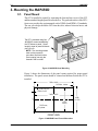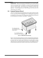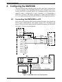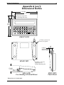
1
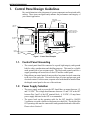
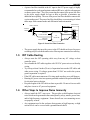
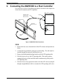
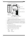
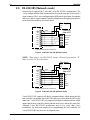
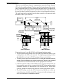
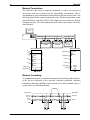
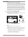
1010-0046A, REV 00
INSTALLATION MANUAL
A
H
O
B
I
P
SHIFT
C
J
Q
V
D
K
R
W
E
L
S
X
F
M
T
Y
G
N
U
Z
#
:
,
1
4
7
SPACE
?
%
$
=
2
5
8
0
*
/
+
-
3
CLEAR
6
DELETE
9
.
E
N
T
E
R
Secure online ordering 24/7/365 from
International Headquarters:
European Headquarters:
707 Dayton Rd. - P.O. Box 1040 - Ottawa, IL 61350 USA
Westlink Commercial Park Oranmore, Co. Galway, Ireland
808 134th Street SW, Suite 120 • Everett, WA 98204
• USA • 425/745-3229
www.bb-elec.com
www.bb-europe.com
Fax:
Phone: 815-433-5100
Fax: 815-433-5104
425/745-3429
• E-mail: [email protected]
• URL: www.maple-systems.com
[email protected]
Phone: +353 91 792444
[email protected]
[email protected]
Fax +353 91 792445
[email protected]
2
MAP450D
COPYRIGHT NOTICE
This manual is a publication of Maple Systems, Inc., and is provided for use by its customers only. The
contents of the manual are copyrighted by Maple Systems, Inc.; reproduction in whole or in part, for use
other than in support of Maple Systems equipment, is prohibited without the specific written permission
of Maple Systems.
WARRANTY
Maple Systems warrants each product to be free from electrical and mechanical defects in materials and
workmanship for a period of one year from the date of shipment. This warranty does not apply to defects
in the Products caused by abuse, misuse, accident, casualty, alteration, negligence, repair not authorized
by Maple Systems, use on current or voltages other than specified by Maple Systems, or application or
installation not in accordance with published instruction manuals. This warranty is in lieu of any other
warranty either expressed or implied.
Maple Systems’ liability is limited to the repair or replacement of the Product only, and not costs of
installation, removal, or damage to user’s property or other liabilities. If Maple Systems is unable to
repair or replace a nonconforming Product, it may offer a refund of the amount paid to Maple Systems
for such Product in full satisfaction of its warranty obligation. Maximum liability of Maple Systems is
the cost of the Product.
Information furnished by Maple Systems, Inc., is believed to be accurate and reliable. However, no
responsibility is assumed by Maple Systems for the use of this information nor for any infringements of
patents or other rights of third parties which may result from its use. No license is granted by
implication, or otherwise, under any patent or patent rights of Maple Systems, Inc. Maple Systems
retains the right to revise or change its products and documentation at any time without notice.
IF SERVICE IS REQUIRED
Package the unit in its original packaging container or, if unavailable, any suitable rigid container. If a
substitute container is used, surround the unit with shock absorbing material; damage in shipment is not
covered by the warranty. Include a letter with the unit describing the difficulty and designating a contact
person. Send to the following address: Maple Systems, Inc., 808 134th Street SW, Suite 120, Everett,
WA 98204.
Only Products that have been issued a Return Material Authorization (RMA) number from Maple
Systems may be returned. All RMAs must be accompanied with a written purchase order for tracking
purposes or, in the case of out-of-warranty repairs, for repair charges on a time and material basis.
All returns will be tested to verify customer claims of noncompliance with the product warranty.
Improper return packaging which makes verification impossible will void the warranty. Products
passing the tests will be returned “AS IS” to the customer.
If noncompliance is verified and is not due to customer abuse or the other exceptions described with
product warranty, Maple Systems will, at its option, repair or replace the Product returned to it, freight
prepaid, which fail to comply with the foregoing warranty, provided Maple Systems is notified of such
noncompliance within the one-year warranty period.
APPLICATIONS ASSISTANCE
This manual is designed to provide the necessary information for trouble-free installation and operation
of your new Operator Interface Terminal (OIT). However, if you need assistance, please call Maple
Systems at 425-745-3229 or visit our web site at www.maple-systems.com.
1010-0046A, REV 00
INSTALLATION MANUAL
3
Read Me First!
Your new Maple Systems OIT comes from the factory configured with the default
communication settings: 9600 baud, no parity, 8 data bits, 1 stop bit, no
handshaking, no turn-around delay, 90° viewing angle, interactive mode, CR line
terminator, underline cursor, 1 space tab width, local echo enabled, local setup
enabled, local keyboard enabled, key click enabled, block echo enabled. You can
change these settings through the MAP450D’s local setup menus or by using the
STEPware-100 configuration software (sold separately). If you want to store
messages in the MAP450D, you must use STEPware-100.
To ensure that the OIT meets CE compliance, it is necessary to follow all
installation procedures described in this manual.
Introduction
Thank you for purchasing a Maple Systems MAP450D. You have selected a
rugged, reliable, and powerful operator interface for your application. This booklet
describes the steps necessary to ensure trouble-free OIT system operation. Please
read this booklet carefully!!
Static Awareness
It is best NOT to remove the rear cover on the OIT except when accessing the
terminal block pins or panel mounting the OIT. When the rear cover is removed,
the circuitry inside is exposed to possible damage by electrostatic discharge during
handling. Minimize the possibility of electrostatic discharge by:
CAUTION
•
•
•
•
Discharging personal static by grounding yourself prior to handling the OIT.
Handling the OIT at static-free, grounded work stations.
Connecting the chassis of the OIT to a clean ground.
Placing the OIT into an anti-static bag during transport.
Unpacking the Unit
Carefully unpack the OIT. Please read any instructions or cautions that appear on
the shipping container. Check all material in the container against the enclosed
packing list. Maple Systems, Inc., will not accept responsibility for shortages
against the packing list unless notified within 30 days. The equipment and its
accessories were inspected and tested by Maple Systems before shipment; all of the
equipment should be in good working order. Examine the equipment carefully; if
any shipping damage is evident, notify the carrier immediately. You are
responsible for claim negotiations with the carrier. Save the shipping container and
packing material in case the equipment needs to be stored, returned to Maple
Systems, or transported for any reason.
1010-0046A, REV 00
4
MAP450D
TABLE OF CONTENTS
1. Control Panel Design Guidelines . . . . . . . . . . . . . . . . . . . . . . . . . . . . . . . . . . . 5
1.1. Control Panel Grounding . . . . . . . . . . . . . . . . . . . . . . . . . . . . . . . . . . . . 5
1.2. Power Supply Selection . . . . . . . . . . . . . . . . . . . . . . . . . . . . . . . . . . . . . 5
1.3. OIT Cable Routing . . . . . . . . . . . . . . . . . . . . . . . . . . . . . . . . . . . . . . . . . 6
1.4. Other Steps to Improve Noise Immunity . . . . . . . . . . . . . . . . . . . . . . . . 6
2. Connecting the MAP450D to a Host Controller. . . . . . . . . . . . . . . . . . . . . . . . 7
2.1. RS-232 (Interactive & Block modes) . . . . . . . . . . . . . . . . . . . . . . . . . . . 9
2.2. RS-422/485 (Interactive & Block modes). . . . . . . . . . . . . . . . . . . . . . . . 9
2.3. RS-422/485 (Network mode) . . . . . . . . . . . . . . . . . . . . . . . . . . . . . . . . 10
2.4. Set Jumper for 3-Wire RS-422/485. . . . . . . . . . . . . . . . . . . . . . . . . . . . 13
3. Mounting the MAP450D . . . . . . . . . . . . . . . . . . . . . . . . . . . . . . . . . . . . . . . . 14
3.1. Panel Mount . . . . . . . . . . . . . . . . . . . . . . . . . . . . . . . . . . . . . . . . . . . . . 14
3.2. Pedestal/Pendent Mount . . . . . . . . . . . . . . . . . . . . . . . . . . . . . . . . . . . . 15
3.3. Benchtop Mount . . . . . . . . . . . . . . . . . . . . . . . . . . . . . . . . . . . . . . . . . . 16
4. Configuring the MAP450D. . . . . . . . . . . . . . . . . . . . . . . . . . . . . . . . . . . . . . . 17
4.1. Connecting the MAP450D to a PC . . . . . . . . . . . . . . . . . . . . . . . . . . . . 17
Appendix A: OIT Hardware Specifications. . . . . . . . . . . . . . . . . . . . . . . . . . . . . 18
Appendix B: Differences Between MAP450D and MAP450B. . . . . . . . . . . . . . 20
1010-0046A, REV 00
INSTALLATION MANUAL
5
1. Control Panel Design Guidelines
Pay careful attention to the placement of system components and associated cable
routing. These items can significantly enhance the performance and integrity of
your control application.
SHIELDED
COMMUNICATION
CABLE
GROUND
STRAP
CONTROLLER
OIT OPERATING
CABLE
OIT REAR
COVER
OIT
CONTROL PANEL
TIED TO RELIABLE
EARTH GROUND
OIT
POWER
SUPPLY
LINE
FILTER
I / O CONTROL LINES
GROUND WIRES
QUIET
GROUND
POWER LINE
FILTER
QUIET GROUND(ISOLATED)
Figure 1 Control Panel Example
1.1. Control Panel Grounding
• The control panel should be connected to a good, high-integrity earth ground
both for safety considerations and shielding purposes. This must be a reliable
earth ground with a low-resistance path. The ideal earth ground would be a
copper grounding rod located close to the OIT and the control panel.
• Hinged doors on control panels do not provide a long term electrical connection
to the rest of the enclosure. Corrosion develops over time and prevents good
electrical contact. For this reason, a separate wire braid should be installed from
the hinged control panel to the rest of the enclosure.
1.2. Power Supply Selection
• The power supply used to power the OIT should have an output between +12
and +30 VDC. The voltage should measure between +12 and +30V at the OIT
between Pins 2 and 3 of the OIT terminal block. A 24 VDC, 0.5 amp linear
power supply dedicated to the OIT is recommended.
• The power leads on the operating cable for the OIT should be 18AWG
2-conductor wire with a shield wire and protective shield foil. The shield of the
OIT operating cable must be connected to earth ground at both ends of the cable.
Please refer to Section 2.
1010-0046A, REV 00
6
MAP450D
• A power line filter installed at the AC input to the OIT power supply is highly
recommended as a safeguard against conducted RF noise, which is often present
on factory power lines. The wires connecting the output of the power line filter
to the power supply should be kept as short as possible to minimize any
additional noise pickup. The case of the power line filter should be connected to
a quiet earth ground. The power line filter should have a current rating of at least
three amps with common mode and differential mode attenuation.
POWER SUPPLY
"QUIET" GROUND
KEEP SHORT
TO EARTH
GROUND
GREEN
WHITE TO
110VAC NEUTRAL
N
G
BLACK TO
110VAC LOAD(HOT)
L
N
WHITE
AC
LINE FILTER
GND
AC
AC
L
BLACK
Figure 2 Power Line Filter Connection
• The power supply that provides power to the OIT should not be used to power
switching relays or solenoids unless noise filter caps are connected to each relay.
1.3. OIT Cable Routing
• Always route the OIT operating cable away from any AC voltage or host
controller wires.
• Never bundle the OIT cables together with 120 VAC power wires or with relay
wiring.
• Try to keep at least 8 inches (20 cm) of separation between the OIT cables and
other power wiring. If voltages greater than 120 VAC are used in the system,
greater separation is required.
• If the OIT cables must come near AC wiring, make sure they cross at 90 degrees.
• Running AC power wires in a separate grounded conduit is the preferred method
for electrical noise reduction.
• Keep the lengths of the OIT cables as short as possible. Do not coil excess cable
and place it next to AC powered equipment.
1.4. Other Steps to Improve Noise Immunity
• Always install the OIT’s rear cover. This provides a shield against electrical
noise which can be generated in the control panel by relays, motors, power lines,
and/or high frequency equipment. Ensure that all rear cover mounting screws
are properly secured.
• Any equipment used in the enclosure that operates at high frequency or high
current levels can be covered with a grounded metal shield.
1010-0046A, REV 00
INSTALLATION MANUAL
7
2. Connecting the MAP450D to a Host Controller
It is necessary to follow all installation procedures described in this chapter for
electrical noise immunity and CE compliance.
Host/Controller
Operating Cable
specific for the
Host/Controller
Tighten
OIT Operating
Cable
Install the
ferrite coil here
OIT Power Supply
Output
Case GND
Terminal
Block
Figure 3 MAP450D Cable Connections
STEPS
1.
Remove the four screws from the back of the OIT enclosure and open the two
halves.
2.
A strain relief is provided for wiring access and sealing. The cable must be
inserted through the strain relief and into the cover.
3.
Remove the black heatshrink tubing from the end of the OIT operating cable.
4.
Slide the ferrite coil over the OIT operating cable. This usually requires
rotating the ferrite coil back and forth while simultaneously pulling on the
OIT operating cable.
5.
Slide the ferrite coil up against the inside wall of the OIT enclosure and pull
through enough additional cable to reconnect the OIT operating cable wires.
1010-0046A, REV 00
8
MAP450D
6.
Connect the OIT operating cable wires to the terminal block. Refer to
sections 2.1 through 2.3 and Figure 4.
Function Pin #
1
+24V
2
COM
3
RXD+ 4
RXD5
TXD+ 6
7
TXDRTN
8
RXD
9
TXD
10
CTS
11
RTS
12
Ferrite coil
Heatshrink tubing
POWER +24V
Connection to
communication
wires of
Host/Controller
COM
RXD+
RXDRS485 TXD+
TXDRTN
RXD
RS232 TXD
CTS
RTS
TB1
1
2
3
4
5
6
7
8
9
10
11
12
Chassis shield wire
Figure 4 Terminal Block Pinout Connection
7.
Pull out any slack from the OIT operating cable.
8.
Rotate the rear of the OIT enclosure back into position while gently pulling
out the new slack generated in the cable as you proceed.
CAUTION: Due to the large size of the ferrite coil, it must be positioned very
carefully. Make sure that when the OIT enclosure halves are brought together, the
ferrite coil is positioned so there is no internal interference. The ferrite coil must be
positioned up against the inside wall of the OIT enclosure with the protruding OIT
operating cable kept short.
9.
Tighten the cable strain relief nut.
10. Re-install the four screws into the back of the OIT enclosure
11. Route the operating cable to the host controller and connect.
12. Route the power pigtail to the OIT power supply.
13. Install the wires into the power supply as follows:
1010-0046A, REV 00
RED
+output
BLACK
-output
SHIELD
case ground.
INSTALLATION MANUAL
9
2.1. RS-232 (Interactive & Block modes)
Interactive and Block modes support the 3-wire RS-232 configuration with TXD,
RXD and signal common. The cable requires an overall shield to protect against
electrical noise. Xon and Xoff can be used for communication handshaking.
3-Wire RS-232
Host Controller
MAP450D Terminal Block
TXD
Pin 9 - RXD
RXD
Pin 10 - TXD
Signal Ground
Pin 8 - Return
2.2. RS-422/485 (Interactive & Block modes)
Interactive and Block modes support the 3-wire and 5-wire RS-422/485
configurations. The 3-wire configuration has both transmit and receive on the same
pair of wires plus a signal common. The 5-wire configuration has differential signal
pairs for transmit and receive plus a signal common. In both configurations the
signal pairs must be twisted and surrounded by an overall shield.
NOTE: When using 3-wire RS-422/485, Jumper JP4 must be in position “B”.
Refer to section 2.4 for instructions.
3-Wire RS-422/485
Host Controller
MAP450D Terminal Block
TXD+ & RXD+
Pins 4 & 6 - RXD+ & TXD+
TXD- & RXD-
Pins 5 & 7 - RXD- & TXD-
Signal Ground
Pin 8 - Return
5-Wire RS-422/485
Host Controller
MAP450D Terminal Block
TXD+
Pin 4 - RXD+
TXD-
Pin 5 - RXD-
RXD+
Pin 6 - TXD+
RXD-
Pin 7 - TXD-
Signal Ground
Pin 8 - Return
1010-0046A, REV 00
10
MAP450D
2.3. RS-422/485 (Network mode)
Network mode supports the 3-wire and 5-wire RS-422/485 configurations. The
3-wire configuration has both transmit and receive on the same pair of wires plus a
signal common. The 5-wire configuration has differential signal pairs for transmit
and receive plus a signal common. In both configurations the signal pairs must be
twisted and surrounded by an overall shield.
Power Supply
+24V
OIT
TB1
1
GND
2
From or To
Host or OIT
* COM
3
RXD+
4
CHASSIS GND
RXD-
5
TXD+
6
TXD* RTN
7
8
+24V
Shield
RXD+/TXD+
RXD-/TXDSIG GND
SIG GND
* RTN and COM are internally connected in OIT.
Figure 5 3-Wire RS-422/485 (Network mode)
NOTE: When using 3-wire RS-422/485, Jumper JP4 must be in position “B”.
Refer to section 2.4 for instructions.
Power Supply
+24V
OIT
+24V
TB1
1
GND
Shield
2
From or To
Host or OIT
* COM
3
RXD+
4
CHASSIS GND
TXD+
RXD-
5
TXD-
TXD+
6
RXD+
TXD* RTN
7
8
RXDSIG GND
SIG GND
* RTN and COM are internally connected in OIT.
Figure 6 5-Wire RS-422/485 (Network mode)
5-wire RS-422/485 supports full-duplex communications; which means that the
host controller can trasmit data to the OITs and receive data from the OITs at the
same time. 3-wire RS-422/485 only supports half-duplex communications; which
means that the host controller cannot transmit and receive data at the same time.
Although 3-wire RS-422/485 installations may be less costly than 5-wire
installations, the increased complexity in programming the host controller for
3-wire RS-422/485 may increase development time.
1010-0046A, REV 00
INSTALLATION MANUAL
11
See
Detail A & B
Less than
4000'
Less than 12"
Shielded Cable
OIT #1
OIT #2
TERMINATOR
HOST
2 Pair Twisted
Shielded Cable
24 Gage Wire
TERMINATOR
There are several different forms of communications networks. Maple Systems’
OITs utilize the multidrop format. The host controller, located at one of the network
ends, is connected to the OITs via a continuous com-link. Each OIT is connected to
the network by locally tapping into the com-link with short stub cables. The end of
the com-link must be properly terminated to reduce noise pickup and interference.
The total length of the com-link, from the host controller to the network cable
terminator, can be up to 4,000 feet.
OIT #100
3 Pair Twisted
Shielded Cable
24 Gage Wire
From Host or
Previous OIT
From Host or
Previous OIT
To More
OITs
SIG GND
RXD-
SIG GND
TXD-
RXD+
TXD+
CHASSIS GND
SIG GND
SIG GND
RXD-/TXD-
Drain
Wires
SIG GND
RXD+/TXD+
RXDTXD-
CHASSIS
GND
Drain
Wires
RXD+
TXD+
CHASSIS GND
To More
OITs
TO OIT
TO OIT
Detail A
5 Wire Termination
Detail B
5 Wire Termination
If you decide to use 3-wire RS-422/485, the following limitations apply:
• The host controller must disable or tri-state its RS-485 transmitter when it is not
sending data to the OITs on the network. To simplify programming, the host
should disable or tri-state its RS-485 receiver whenever transmitting.
• The ability to stay logged on to a particular OIT by sending the command terminator
instead of the line terminator is not available in this mode. Therefore, each command
sent from the host controller should end with the appropriate line terminator.
• If the host controller sends a command that requires a response from the OIT, the
host controller must wait for a response from the OIT before sending another
command. Otherwise, a situation can occur in which the OIT and the host
controller attempt to transmit at the same time cuasing unpredictable results.
• The ASCII strings sent by the OIT’s function keys should not include any
control characters which the other OITs on the network could misinterpret, such
as the line terminator or command terminator.
1010-0046A, REV 00
12
MAP450D
Network Termination
The com-link cable must be properly terminated to reduce the amount of
interference and noise pickup from the surrounding environment. This is
accomplished by using a termination circuit at both ends of the network cable. The
following figure shows a typical termination circuit. The host termination is only
needed if the host controller’s RS-422/485 adapter does not contain any built-in
terminator circuitry. The end termination must be done at the extreme end of the
com-link cable.
TERMINATOR
TERMINATOR
HOST
OIT3600
Vcc
MAP460D
OIT3160
HOST TERMINATION
END TERMINATION
FROM HOST +
Tx+
Tx-
Rx+
RxSIGNAL GND
FROM HOST -
470 Ohm
to
10 KOhm
120 Ohm
to
240 Ohm
TO HOST +
120 Ohm
to
240 Ohm
470 Ohm
to
10 KOhm
TO HOST SIGNAL GND
SHIELD
CHASSIS GND
DO NOT
CONNECT
EARTH
GROUND
Network Grounding
To communicate properly, serious attention must be paid to the grounding scheme
of the devices connected to the com-link. Improper grounding, improper
termination, and faulty shielding of the com-link are the most common causes of
system failure in a multidrop network.
Shield
Signal Ground
Signal Ground
From Host +
From Host -
From Host
To Host +
To Host -
To Host
Shield
To OIT
1010-0046A, REV 00
To OIT
INSTALLATION MANUAL
13
The cable shield must not be used as the signal ground.
It is tempting to try and reduce the cost of 5-wire cabling by using a 4-wire cable
with the shield used as the signal ground. DON’T DO IT. The initial cost savings
are always exceeded by the maintenance costs once the system is operating under
field conditions. It is often necessary to completely replace the network com-link
with the proper cable (5-wire plus shield) to eliminate noise problems in the system.
The signal ground must not be connected to the chassis or earth ground.
The chassis or earth ground is intended as a safety ground for power supplies, EMI
filters, voltage spike protection circuits, 120 VAC neutral returns, and all manner of
AC and DC driven devices. As a result, the chassis or earth ground can carry large
voltage potentials and currents. Connecting the signal ground to chassis or earth
ground can damage the devices connected to the com-link.
2.4. Set Jumper for 3-Wire RS-422/485
This step is required only if the OIT will be communicating with the host controller
using RS-485 half-duplex 3-wire communication.
JP4
A
(Display)
B
A
JP4
(CPU Board)
B
JP4
A
B
Position "A",
Position "B",
Normal
Half-Duplex 3-Wire
RS485
Figure 7 MAP450D Jumper Installation
STEPS
1.
Remove the protective cover from the rear of the unit.
CAUTION: When the rear cover is removed, the circuitry inside is exposed to
possible damage by electrostatic discharge. Refer to Static Awareness on page 4.
2.
Locate jumper “JP4” using Figure 7 as a guide. The jumper is installed on
the upper two pins of a 3-pin header. This is called Position “A”.
3.
Move the jumper to the lower two pins of the 3-pin header (Position “B”).
Ensure that the jumper is pressed fully into place.
4.
Replace the rear cover and the four retaining screws.
1010-0046A, REV 00
14
MAP450D
3. Mounting the MAP450D
3.1. Panel Mount
The OIT is installed in a panel by separating the front and rear covers of the OIT,
and then sandwiching the panel between the two. The gasketed surface of the OIT’s
front cover provides the environmental seal to NEMA 4 and NEMA 12 standards.
The rear cover helps shield the OIT from dust, dirt, induced electrical noise, and
physical damage.
The OIT is mounted using four
#6-32UNC screws sandwiching
the OIT halves to panel. Screw
length is equal to panel thickness
plus 1/2 inch.
NOTE: The mounting screws
must not be torqued to
more than 18 pound-inches.
Over-torquing can strip the
threads in the front half.
Figure 8 MAP450D Panel Mounting
Figure 9 shows the dimensions of the panel cutout required for proper panel
installation. The panel cutout should be cleaned and deburred before the OIT is
installed.
7.580 +/-0.010
0.156 dia., 4 holes
0.180 +/-0.015
0.060 +/-0.015
7.460 +/-0.015
4.460
+/-0.010
CL
4.100
+/-0.015
R 0.03 max.,
4 places
CL
FRONT VIEW
Figure 9 MAP450D Panel Cutout Dimensions
1010-0046A, REV 00
INSTALLATION MANUAL
15
IMPORTANT: When panel mounting the MAP450D, do not catch the display
connector on the panel cutout. The display is exposed while panel mounting and
extra care should be taken. The display can be damaged if the display cable
connector, which protrudes from the panel cutout, is touching the panel when
tightened. To avoid damage, place the MAP450D gently onto the panel while
monitoring for this condition.
3.2. Pedestal/Pendent Mount
The OIT is installed onto a pedestal/pendent by removing the four rubber feet from
the rear cover of the OIT, then attaching the OIT to a mounting plate using the four
pre-tapped holes in the rear cover. The OIT enclosure and cable strain relief provide
the environmental seal to NEMA 4 and NEMA 12 standards.
Four #6 external tooth
star lockwashers provide
chassis ground
Four #6-32UNC mounting
screws secure OIT to pedestal
Figure 10 MAP450D Pedestal Mounting
Figure 11 shows the minimum dimensions of the pedestal/pendant mounting plate.
The area on the pedestal/pendant mounting plate around the mounting holes (where
the heads of the screws make contact) should have any existing paint or plating
removed to allow for a good chassis ground connection. The mounting screws are
installed using external tooth star washers to ensure a positive ground connection.
1010-0046A, REV 00
16
MAP450D
5.400 +/-0.015
2 places
0.156 dia. nominal,
4 holes(clearance
for #6 screws)
PEDESTAL
MOUNTING
PLATE
4.600 +/-0.015
2 places
5.00 nominal
(1/8" thick min. recommended)
6.00 nominal
Figure 11 Pedestal/Pendant Mounting Plate Dimensions
The OIT is connected to the mounting plate with four #6-32UNC screws. The
length of the mounting screws is equal to the plate thickness plus 1/4 inch.
NOTE: The mounting screws must not be torqued to more than 18 pound-inches.
Over-torquing can strip the threads in the enclosure.
3.3. Benchtop Mount
The MAP450D’s rear cover has two legs set at a five degree angle to give the display
and keypad a sloped front while sitting on a bench. Four rubber feet are attached to
the legs to prevent slippage as well as damage to the surface of the bench.
Figure 12 MAP450D Benchtop Mounting
1010-0046A, REV 00
INSTALLATION MANUAL
17
4. Configuring the MAP450D
The MAP450D has many operating parameters that control how it communicates
to the host controller. These operating parameters can be changed in three ways:
from the MAP450D’s keyboard when it is in Configuration mode, when the host
controller sends a Configuration Control Command, or by downloading a
STEPware-100 project. This chapter explains how to connect the MAP450D to a
PC so you can download a project from the STEPware-100 configuration software.
4.1. Connecting the MAP450D to a PC
First, remove the operating cable from the terminal block pins. Next, connect an
RS-232 serial communications cable (Maple Systems P/N 7431-0048) to the
proper COM port on your computer and the terminal block pins on the MAP450D.
See Figure 13 below for pin assignments.
Power
Supply
GND
Red
Black
PC
9S
+24V
GND
5
TXD
3
RXD
2
DCD
1
DTR
4
DSR
6
RTS
7
CTS
8
OIT
Black
TB1
Shield
Red
Blk
Green
White
PC
1
2
3
+24V
COM
9 RXD
10 TXD
OIT
Back
of
OIT
Printer
Com2 Com1
OIT Power Supply
GND -
+
Maple Systems
OIT to PC cable
(If mouse is using
Com 1, use Com2)
7431-0048
Figure 13 MAP450D to PC RS-232 Communication
1010-0046A, REV 00
18
MAP450D
Appendix A
OIT Hardware Specifications
Mechanical
Material: Cast aluminum enclosure sealed to NEMA 4/12
Mounting: Panel, pedestal, pendant, or benchtop
Wiring: Unit is field-wired by user to internal terminal block pins
Weight: 2 pounds (0.90 kg)
Environmental
Operating Temp: +32 to +122°F (0 to +50°C)
Storage Temp: -4 to +158°F (-20 to +70°C)
Electric Noise Immunity
Emissions:
Immunity:
EN55011 (Group 1, Class B) — Generic commercial, light, and heavy industrial environments
EN50081-1 — Generic domestic and light industrial environments
EN50081-2 — Generic heavy industrial environment
EN50082-1 — Generic domestic and light industrial environments
EN50082-2 — Generic heavy industrial environment
Power Requirements
Input Voltage: 12 to 30 VDC
Power Usage: 2.5 watts typical
Display
Display Type (MAP450D-003): Liquid Crystal Display (LCD)—5 x 7 dot matrix with cursor
Display Type (MAP450D-004): Backlit Liquid Crystal Display (LCD)—5 x 7 dot matrix with cursor
Display Character Size: 2 lines by 40 characters, 0.2 inches (5 mm) high
Display Viewing Angle: Approximately 120 degrees
Keypad
Key Type: Membrane switch
Feedback: Internal buzzer
Layout: 42 alphanumeric keys arranged in 4 rows of 11 keys
Operational Life: Five million operations, minimum
Customizing: Custom keypad overlay available
Communications
Serial Port: RS-232, RS-422, or RS-485
Baud Rates: 300, 600, 1200, 2400, 4800, 9600, or 19.2k
Internal Features
Memory: 128K x 8 Flash PROM for firmware, protocol and configuration data—no battery required
1010-0046A, REV 00
INSTALLATION MANUAL
19
Appendix A (con’t)
Dimensional Outline
8.12 [206]
7.10 [180]
Waterproof strain relief
for operating cable entry
5.75
[146]
5.00
[127]
FRONT VIEW
6-32UNC x 0.50 [12.7]
screw, SS, 4 places
REAR VIEW
(Panel)
0.90 [23]
depth behind the
front of a panel
6-32UNC x 0.30 [7.6]
deep threads, for
Pedestal Mounting only
1.70 [43]
overall
SIDE VIEW,
Free-Standing & Pedestal-Mount
SIDE VIEW,
Panel-Mount
Dimensions are in inches [mm].
1010-0046A, REV 00
20
MAP450D
Appendix B
Differences Between MAP450D and MAP450B
The MAP450D uses the same enclosure, display, keyboard and overlay as the MAP450B, but
includes the following differences:
1.
The MAP450D can be configured using the Windows-based STEPware-100 configuration
software.
2.
The MAP450D stores and displays up to 500 user-definable messages.
3.
The MAP450D stores the configuration parameters and user-definable messages in flash
memory.
4.
The MAP450D is CE certified; it passes strenuous tests for noise immunity and emissions.
5.
Local setup mode is entered by pressing and holding the Clear key instead of the S key
while the <<<Initializing>>> prompt is on the display. Local setup mode can also be
entered after initialization by pressing the Enter key three times.
6.
The power supply input requirement is +12 to 30 VDC instead of +5or 8 to 13 VDC.
7.
The MAP450D offers 2 LCD viewing angles instead of 10.
8.
The MAP450D uses a non-removable terminal block instead of a removable terminal block
for both the communications and power wiring.
9.
The Set Serial Interface Command (ESC S) is no longer supported. To maintain backwards
compatibility the command is recognized but ignored.
1010-0046A, REV 00