1
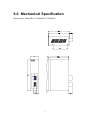
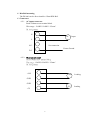
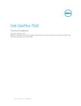
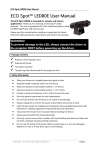
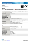
DP-660
Industrial Power Supply
User’s Manual
Introductions ..................................................................................................................1
1.0
Input Specifications ...............................................................................1
2.0
Output Specifications.............................................................................1
3.0
General Features ....................................................................................2
4.0
Environment specifications....................................................................2
5.0
International standards ...........................................................................3
6.0
Mechanical Specification.......................................................................4
Introductions
The DP-660 is a dual output, DIN-Rail mounted, 65 watts switching power supply.
It has over voltage protection in main output and over load latch off mode
protection on all output.
1.0 Input Specifications
1.1 Input voltage
The range of input voltage is from 85VAC to 270VAC
1.2 Input Frequency
The range of input frequency is from 47Hz to 63Hz.
1.3 Input current
The maximum input current is 2A at 115VAC or 1A at 230VAC.
1.4 Inrush current
The inrush current will not exceed 60A at 115VAC input or 30A at 230VAC
input, cold start, 25deg. C.
2.0 Output Specifications
2.1 Load range
Output
Min. load
Rated load
Peak load
Voltage accuracy
+24V
0A
2.5A
6A
23.76V to 24.24V
+5V
0a
0.5A
4.75V to 5.25V
At Factory, all outputs in 60% rated load conditions, the +24V output is set
to between 23.76V and 24.24V and 5V is checked to be within the specified
voltage accuracy range.
Peak load can test for 10 sec. Typical when other output at rated load, AC
input at 115VAC.
2.2 Ripple and noise
the peak-to-peak ripple and noise for each output is less then 1% of output
voltage at rated load. Measuring is done by 15MHz bandwidth limited
oscilloscope and terminated each output with a 0.47uF capacitor.
2.3 Line regulation
the line regulation for each output is less then +/- 1% while measuring at
1
rated load and +/- 10% of input voltage changing.
2.4 Load regulation
The load regulation for +24V is less then +/-1%, for +5V is less then +/-5%,
measuring is done by changing the measured output load +/-40% from 60%
rated load, and keep other output at 60% rated load.
2.5 Step regulation
When +24V load changes from min. to peak load or from load to min. load ,
the 5V should keep within 5V +/-5% at rated load.
3.0 General Features
3.1 Efficiency
The efficiency is higher than 75% while measuring at nominal line and rated
load.
3.2 Hold up time
The old up time is longer than 16ms at 115VAC input and rated load, which
is measured from the end of the last charging pulse to when the main output
drops down to 95% output voltage.
3.3 Protection
For some reason the power supply fails to control itself, the build-in over
voltage protection circuit will shut down the outputs to prevent damaging
external circuits. The trip point is around 26V to 31V. The power supply will
go into latch-off mode against short circuit or over load conditions, and have
to OFF and ON the AC input to restart the power supply.
4.0 Environment specifications
4.1 Operation temperature
0 deg C to 50 deg C (Normal output current)
50 deg C to 75 deg C (65% output current)
4.2 Storage temperature
-40 deg C to 85 deg C
4.3 Altitude
will operate properly at any altitude between 0 to 10000ft.
2
5.0 International standards
The following data is by open frame testing (Board only).
Internal PCB model No.: SNP-9069
5.1 Safety standards
Designed to meet the following standards:
UL 1950 D3
CSA 22.2 No. 234
VDE EN 60 950
5.2 EMI standards
Designed to meet the following conducted limits.:
FCC docket 20780 curve “B”
VFG 243
3
6.0 Mechanical Specification
Dimensions: 44mm(W)x 150mm(H)x 122mm(D)
6.1
y
l
p
p
u
S
r
e
w
o
P
l
a
i
r
t
s
u
d
n
I
DP-660
D
N
G
D
N
G
5
t
u
p
t
u
O
A
5
.
2
/
V
4
2
+
C
D
A
5
.
0
/
V
5
+
C
D
N
L
.
C
.
N
C
A
V
4
6
2
~
5
8
.
G
.
F
A
z
2
H
/
0
~
6
V
/
5
0
1
5
1
t
u
p
n
I
A
1
/
~
V
0
3
2
4
6.1 Din-Rail mounting
The DP-660 can be direct install to 35mm DIN-Rail.
6.2 Connectors
6.2.1 AC inputs connector:
Pitch 5.08mm screw terminal block
Wire range : 12AWG~22AWG / 2.5mm²
Pin Assignments:
N
AC
Input
L
No connection
N.C.
Frame Ground
F.G.
6.2.2
DC output connector:
Pitch 5.08mm screw terminal block
Wire range : 12AWG~22AWG / 2.5mm²
Pin Assignments:
+24V
+24V
Loading
+5V
Loading
GND
GND
+5V
5