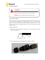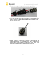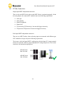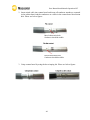
1
User Manual Installation & Operation V4.7 I NDEX Index .......................................................................................................................................................................................... 1 1. 2. 3. 4. 5. Notes on this manual........................................................................................................................................ 3 1.1 Scope of Validation...........................................................................................................3 1.2 Symbols Used...................................................................................................................4 1.3 Target Group....................................................................................................................5 Preparation .............................................................................................................................................................. 6 2.1 System Demonstration......................................................................................................6 2.2 Safety Instructions............................................................................................................7 2.3 Explanations of Symbols on Inverter ..................................................................................9 Product Information ......................................................................................................................................10 3.1 Overview .......................................................................................................................10 3.2 Major Characteristics......................................................................................................11 3.3 Datasheet ......................................................................................................................12 Unpacking................................................................................................................................................................13 4.1 Assembly parts...............................................................................................................13 4.2 Product Appearance .......................................................................................................15 4.3 Product Identification .....................................................................................................18 4.4 Further Information........................................................................................................19 4.5 Customer notice .............................................................................................................19 Installation..............................................................................................................................................................20 5.1 Safety ............................................................................................................................20 5.2 Mounting Instructions.....................................................................................................21 5.3 Safety Clearance .............................................................................................................22 5.4 Mounting Procedure.......................................................................................................23 5.5 Safety Lock.....................................................................................................................26 5.6 Check Varistors...............................................................................................................28 1 User Manual Installation & Operation V4.7 6. Electrical Connection.....................................................................................................................................30 6.1 Safety ............................................................................................................................30 6.2 Overview of Connection Area..........................................................................................31 6.3 AC Side Connection.........................................................................................................33 6.4 DC Side Connection ........................................................................................................36 6.5 DC Side Adapter plug & Cable requirements .....................................................................42 6.6 DC Side Disconnection ....................................................................................................43 6.7 Communication and Monitoring Device ...........................................................................44 7. Configuration........................................................................................................................................................45 7.1 LCD Display ....................................................................................................................45 7.2 Setup .............................................................................................................................47 7.3 Event number table ........................................................................................................53 7.4 Further information for the event record .........................................................................54 8. Recycling and Disposal .................................................................................................................................61 9. Guaranty Scope and Guaranty Service............................................................................................62 9.1 Macsolar Factory Guaranty Scope....................................................................................62 9.2 Guaranty Conditions.......................................................................................................62 9.3 Guaranty Exclusion .........................................................................................................63 10. Contact ...................................................................................................................................................................64 11. System Commissioning Confirmation Report......................................................................65 Abbreviation....................................................................................................................................................................71 2 User Manual Installation & Operation V4.7 1. NOTES ON THIS MANUAL 1.1 Scope of Validation The main purpose of this User’s Manual is to provide instructions and detailed procedures for installing, operating, maintaining, and troubleshooting the following Macsolar Grid-Tied Solar Inverter: Macsol-TL3K Macsol-TL3.6K Macsol-TL4K Macsol-TL5K Please keep this manual all time available in case of emergency. 3 User Manual Installation & Operation V4.7 1.2 Symbols Used DANGER DAN GER indicates a hazardous situation which, if not avoided, will result in death or serious injury. WARNING WARNING indicates a hazardous situation which, if not avoided, can result in death or serious injury or moderate injury. CAUTION CAUTION indicates a hazardous condition which, if not avoided, can result in minor or moderate injury. or moderate injury. NOTICE NOTICE indicates a situation that can result in property damage, if not avoided. 4 User Manual Installation & Operation V4.7 1.3 Target Group Chapter 1, 2, 3, 4, 7, 8, 9, 10 and Chapter 11 are intended for anyone who is intended to use Macsolar Grid-Tied Solar Inverter. Before any further action, the operators must first read all safety regulations and be aware of the potential danger to operate highvoltage devices. Operators must also have a complete understanding of this device’s features and functions. WARNING Do not use this product unless it has been successfully installed by qualified personnel in accordance with the instructions in Chapter 5, “Installation”. Chapter 5, and Chapter 6 are only for qualified personnel who is intended to install or uninstall the Macsolar Grid-Tied Solar Inverter. NOTICE Hereby qualified personnel means he/she has the professional training, knowledge, and experience in: • Installing electrical equipment and PV power systems (up to 1000 V). • Applying all applicable installation codes. • Analyzing and reducing the hazards involved in performing electrical work. • Selecting and using Personal Protective Equipment (PPE). All installation, commissioning, maintenance, repair and recycling of Macsolar Inverter must be done only by qualified personnel. 5 User Manual Installation & Operation V4.7 2. PREPARATION 2.1 System Demonstration Solar energy generation systems, based on photovoltaic modules, nowadays represent the most suitable solution, in particular for domestic power levels, to reduce the energy consumption produced by oil and gas. Moreover in different European countries, electricity companies are providing money incentives for the energy produced by renewable sources and injected into the utility grid. The solar inverter is a critical component in a solar energy system. It performs the conversion of the variable DC output of the PV modules into a clean sinusoidal 50 or 60 Hz AC current that is then applied directly to the commercial electrical grid or to a local grid electrical network. Typically, communications capability is included so users can monitor the inverter and report on power and operating conditions, provide firmware updates and control the inverter grid connection. Depending on the grid infrastructure wired (RS-485, CAN, Power Line Communication, Ethernet) or wireless (Bluetooth, ZigBee/IEEE802.15.4, 6loWPAN) networking options can be used. 6 User Manual Installation & Operation V4.7 2.2 Safety Instructions DANGER DANGER due to electrical shock and high voltage DO NOT touch the operating component of the inverter, it might result in burning or death. TO prevent risk of electric shock during installation and maintenance, please make sure that all AC and DC terminals are plugged out. DO NOT touch the surface of the inverter while the housing is wet, it might lead to electrical shock. DO NOT stay close to the instruments while there are severe weather conditions including, storm lighting, and etc. WARNING The installation service recycling and disposal of the inverters must be performed by qualified personnel only in compliance with national and local standards and regulations. Please contact your dealer to get the information of authorized repair facility for any maintenance or repairmen. Any unauthorized actions including modificatio n of product functionality of any form will affect the validation of warranty service,Macsolar may deny the obligation of warranty service accordingly. 7 User Manual Installation & Operation V4.7 CAUTION The PV inverter will become hot during operation please don’t touch the heat sink or peripheral surface during or shortly after operation. Risk of damage due to improper modifications. Never modify or manipulate the inverter or other components of the system. NOTICE Public utility only The PV inverter designed to feed AC power directly to the public utility power grid,do not connect AC output of the device to any private AC equipment. The electricity just for consult in the Arm board of inverter, not use for calculate 8 User Manual Installation & Operation V4.7 2.3 Explanations of Symbols on Inverter Symbol Description Dangerous electrical voltage This device is directly connected to public grid, thus all work to the inverter shall only be carried out by qualified personnel. DANGER to life due to high electrical voltage! There might be residual currents in inverter because of large capacitors. Wait 10 MINUTES before you remove the front lid. NOTICE, danger! This device directly connected with electricity generators and public grid. Danger of hot surface The components inside the inverter will release a log of heat during operation, DO NOT touch aluminum housing during operating. A record has occurred Please go to Chapter 7.4 “ Further information for the event record” to remedy the record. This device SHALL NOT be disposed of in residential waste Please go to Chapter 8 “Recycling and Disposal” for proper treatments. Without Transforme r This inverter does not use transformer for the isolation function. German mark of conformity The inverter complies with the requirement of the German Grid Regulations. Certified Safety The inverter complies with the requirements of the Equipment and Product Safety Act in Europe. CE Mark Equipment with the CE mark fulfils the basic requirements of the Guideline Governing Low-Voltage and Electromagnetic Compatibility. No unauthorized perforations or modifications Any unauthorized perforations or modifications are strictly forbidden, if any defect or damage (device/person) is occurred, Macsolar shall not take any responsibility for it. 9 User Manual Installation & Operation V4.7 3.PRODUCT I NFORMATION 3.1 Overview 10 User Manual Installation & Operation V4.7 3.2 Major Characteristics Macsolar inverter has following characteristics which make Macsolar inverter “High Efficiency, High Reliability, High Cost Effective Ratio” • High DC input voltage, can be connected with more PV panels. • Wide MPPT voltage range can fit in different locations or various weather conditions. • High MPP tracking accuracy, catch most of energy from panels and converts it into money in your pocket. • Complete set of protection methods. Also, following protection methods are integrated in Macsolar inverter: • • • • • • • Internal overvoltage DC insulation monitoring Ground fault protection Grid monitoring Ground fault current monitoring DC current Injection monitoring Integrated DC switch 11 User Manual Installation & Operation V4.7 3.3 Datasheet 12 User Manual Installation & Operation V4.7 4. UNPACKING 4.1 Assembly parts After you receive the Macsolar inverter, please check if there is any damage on the carton. Also, please check the inside completeness and for any visible external damage on the inverter or any accessories. Contact your dealer if anything is damaged or missing. 13 User Manual Installation & Operation V4.7 Object A(customized) A1(customized) A2(customized) A3(customized) A4(customized) A5(customized) A6(customized) B C D E F G H I J K Quantity Description 1 Inverter Macsol- TL3K 1 Inverter Macsol- TL3.6K 1 Inverter Macsol- TL4K 1 Inverter Macsol- TL5K 1 Inverter Macsol- TL3K(2MPPT) 1 Inverter Macsol- TL3.6K(2MPPT) 1 Inverter Macsol- TL4K(2MPPT) 1 Rear panel 1sets or 2 sets DC connector 1 AC connector 4 ST6×50 Expansion screw 4 Expansion tube 1 M6×12 cross recessed pan head screw and washer connecting the rear panel with inverter 1 Ring tool to disconnect DC connector 4 Washer Ф 6 1 Installation guide, including user manual 1 Quality certificate card 14 User Manual Installation & Operation V4.7 4.2 Product Appearance Front: B C D E A Object A B C D E F Description Removable front lid for potential maintenance and repair LED light-RUN LED light-FAULT LED light-POWER LCD screen for checking the operating status and configuration Control keyboard for displays and configuration of parameters 15 F User Manual Installation & Operation V4.7 Bottom: Single - input MPPT display picture C A D B E PV1 G F PV2 Ipv1 ≦ Max. Input Current Upv1 ≦ Absolute DC Voltage Object Description A B DC switch to turn off the inverter manually DC input , Anode connected with anode ,cathode connected with cathode, the summation of two route import electricity ≤inverter the biggest import electricity , the same two route pressure and import pressure ≤ inverter the biggest import pressure. C D E F G Plugs for connecting the RS485 communication module. AC output Heat sink Extra lock Inductor box 16 User Manual Installation & Operation V4.7 Dual- input MPPT display picture A C B E F PV1 D G PV2 Connect method see 6.4 Dual-input MPPT independent connection Object Description A B C D E F G DC switch to turn off the inverter manually DC input Plugs for connecting the RS485 communication module. AC output Heat sink Extra lock Inductor box 17 User Manual Installation & Operation V4.7 4.3 Product Identification You can identify the inverter by the side type label. Information such as serial number (SN.), type of the inverter, as well as inverter specifications are specified on the side type label. The type label is on the middle part of the right side of the inverter housing. ( Side type label example as on Macsol-TL5K ) 18 User Manual Installation & Operation V4.7 4.4 Further Information If you have any further questions concerning the type of accessories or installation, please check our website www.macsolar-power.com or contact our service hotline. 4.5 Customer notice After purchase this product, post guarantee slip back to company, or take a picture of guarantee slip, upload the electron picture on the website, our company can supply the service for the customer, no guarantee slip ,the company will not irresponsible for the customer. Address:Level 4, 7/836 Shengli Road, Pudong, 201201, Shanghai, P.R. China Tel: (+86)-21-50720885 / (+86)-21-68689998 Fax: (+86)-21-50720639 Consignee:SHANGHAI MACSOLAR POWER CO.,LTD website:www.macsolar-power.com 19 User Manual Installation & Operation V4.7 5. INSTALLATION 5.1 Safety DANGER DAN GER to life due to potential fire or electricity shock. DO NOT install the inverter near any inflammable or explosive items. This inverter will be directly connected with HIGH VOLTAGE power generation device, the installation must be performed by qualified personnel only in compliance with national and local standards and regulations. Setting the inverter, do not set the inverter under the range of sunshine. Suggest set back PV or under eave, avoid the sun shine shooting straight. NOTICE NOTICE d ue to the inappr opr ia te or the har mo nized ins ta lla tio n e nviro nme nt ma y jeop ard ize the life s pa n o f the inve rte r. Installation directly expose under intensive sunshine is not recommended. The installation site MUST have good ventilation condition. 20 User Manual Installation & Operation V4.7 5.2 • • • • • • • • • • Mounting Instructions Macsolar inverter is designed for installation both indoors and outdoors Please only mount the inverter in the direction as illustrated above Installation of the inverter in the vertical direction is recommended Tilted backwards by max.15 degree is allowed Never install the device with a forward tilt, horizontally or even upside down For the convenience of checking the LCD display and possible maintenance activities, please install the inverter at eye level Make sure the wall you selected is strong enough to handle the screws and the weight of the inverter Ensure the device is properly fixed to the rear panel It is not recommended to install the inverter directly exposed in strong sunshine, the excess heating might lead to power reduction Make sure the ventilation of the installation spot, not sufficient ventilation may affect the operating performance of the electronic components inside the inverter and the life span of the inverter might be jeopardized 21 User Manual Installation & Operation V4.7 5.3 Safety Clearance To make sure the ventilation of the installation spot, if there are multiple Macsolar inverters installed in the same area, the following safety clearance shall be followed for proper ventilation conditions. Direction Above Below Side Front Minimum Clearance 30 cm 50 cm 30 cm 5 cm 22 User Manual Installation & Operation V4.7 5.4 Mounting Procedure 1. Use the rear panel in the package as a drilling template and mark the positions of holes to be drilled (A/B/C/D1 or D2/E). Depending on the dimension of the wall, you have the free choice to mark position D1 or D2 for hole drilling. A B C D1 D2 E 23 User Manual Installation & Operation V4.7 2. According to the marks, drill 4 holes (A/B/C/D1 or D2) in the wall, and then place four expansion tubes in the holes using a rubber hammer. 3. Mount the rear panel. Wring four screws into the expansion tubes and tightly mount the rear panel on the wall. 24 User Manual Installation & Operation V4.7 4. Carefully attach the inverter to the rear panel according to the position of the screws. Make sure the backside of the inverter is closely against the rear panel. When two people transport the inverter, make sure each one use the hand grip in right position as illustrated in the picture. 5. When the inverter is tightly attached to the rear panel, wring the screw in position E. 6. Please carefully check the accessories and original carton to make sure during the installation every necessary part is used and nothing is missing. 25 User Manual Installation & Operation V4.7 5.5 Safety Lock To prevent possible theft activity, Macsolar gives you an extra guard for your property. It is possible to lock the inverter to the rear panel with a padlock. Recommended padlock dimension: A B C 6~9 mm A.Shackle Diameter 8~15 mm B.Vertical Clearance 12~20 mm C.Horizontal Clearance Stainless, solid hanger and secured lock cylinder NOTICE For fur the r ma inte na nce a nd po ss ib le rep a ir, p le ase keep the ke y o f the pad lock in a sa fe p lace. 26 User Manual Installation & Operation V4.7 After the inverter is attached to the rear panel, look at the bottom of the inverter, then the lock position will show as the following picture: 27 User Manual Installation & Operation V4.7 5.6 Check Varistors If the one or more of the varistors might be out of function, please check or replace the varistors according to the following steps: 1. Loosen all 6 captive screws of the removable front lid. Right after the 6 captive screws are removed, please keep them at a distance. Lift the lid upwards and remove it. 2. Then you will see the 5 varistors in 2 groups: 4 in the left side and 1 in the middle area. 28 User Manual Installation & Operation V4.7 2 Remove and install the varistors Remove: First use specified tool and insert it to three holes in the left side of the varistor, then press it to the end. Pull the varistor out. Install: Use specified tool and insert it to three holes in the left side of the varistor, then press it to the end. Press the varistor in. 3 Put the lid back and re-screw all 6 screws, make sure the lid is tighten to the inverter. 29 User Manual Installation & Operation V4.7 6. ELECTRICAL C ONNECTION 6.1 Safety DANGER DAN GER to life due to potential fire or electricity shock. With the inverter powered, comply with all prevailing national regulations on accidents prevention. This inverter will be directly connected with HIGH VOLTAGE power generation device, the installation must be performed by qualified personnel only in compliance with national and local standards and regulations. NOTICE Elec tr ica l co nnec tio ns s ha ll be car r ied o ut in ac cord a nce with the app lic ab le r e gulatio ns, s uc h a s co nd uc tor sectio ns, fuses , P E co nnec tio n. 30 User Manual Installation & Operation V4.7 6.2 Overview of Connection Area Bottom: Single- input MPPT display picture C D B A L E F G PE PV1 PV2 N L Ipv1 ≦ Max. Input Current Upv1 ≦ Absolute DC Voltage Object Description A B DC switch to turn off the inverter manually DC input, Anode connected with anode ,cathode connected with cathode, the one route import electricity ≤inverter the biggest import electricity , the one route pressure and import pressure ≤ inverter the biggest import pressure. C D E F G Plugs for connecting the RS485 communication module. AC output (left-PE, right-N, down-L) Heat sink Extra lock Inductor box 31 User Manual Installation & Operation V4.7 Dual-input MPPT display picture A B E C G F PV1 D PV2 Connect method see 6.4 Dual-input MPPT independent connection Object Description A B C D E F G DC switch to turn off the inverter manually DC input Plugs for connecting the RS485 communication module. AC output (left-PE, right-N, down-L) Heat sink Extra lock Inductor box 32 User Manual Installation & Operation V4.7 6.3 AC Side Connection DANGER DAN GER to life due to potential fire or electricity shock. NEVER connect or disconnect the connectors under load. Integrated RCD and RCM The Macsolar inverter is equipped with integrated RCD (Residual Current Protective Device) and RCM (Residual Current Operated Monitor). The current sensor will detect the volume of the leakage current and compare it with the pre-set value. If the leakage current is above the permitted range, the RCD will disconnect the inverter from the AC load. Assembly Instructions: 1. Strip the cable with the length 0.276 inches (9/32”) - (7mm) and please be careful NOT to nick conductors. 2. Screw off and separate each component of AC connector as follows. 33 User Manual Installation & Operation V4.7 3. Pass the cable through each component from left to the right as follows. 4. Use a screw driver and loose the three screws at the side of the straight plug. Then insert the stripped N, L and PE cable accordingly to the corresponding position and fully tighten the screws. 5. Aim the terminals on the straight plug to the holes of the grommet, and then compress them together. It is recommended to use the AC connection cable wrapping three stranded conductors (circled part in picture below), whose performance is qualified to pass the insulation as well as Hi-Pot tests. 34 User Manual Installation & Operation V4.7 6. Finally, connect the straight plug to the AC terminal on inverter. Pay attention to the polarity of the terminals to avoid wrong connecting. AC output terminal from the inverter 7. The diameter of DC and AC cable should be featured with sufficient currentcarrying capability. 35 User Manual Installation & Operation V4.7 6.4 DC Side Connection Single- input MPPT independent connection There is only one MPP Tracker (the second MPP Tracker is optional equipped), for the two string inputs, the connected PV modules must meet following requirements: Same type Same quantity Identical alignment Identical tilt PV1electricity+PV2electricity≦inverter the biggest electricity PV1pressure=PV2pressure≦inverter the biggest electricity Dual- input MPPT independent connection There are two MPP Trackers, thus each string input can connected with different type of PV modules as long as they meet following requirements The inverter with dual- input MPPT configuration: the dual- input PV input terminals need to be connected with two- group independent PV strings respectively. The inverter can achieve the maximum output power. 40%-60% of the Max. DC Power 40%-60% of the Max. DC Power √ 36 User Manual Installation & Operation V4.7 Dual- input MPPT paralleled connection: The following three methods are not be permitted. 40%-60% of the Max. DC Power 40%-60% of the Max. DC Power × 40%-60% of the Max. DC Power 40%-60% of the Max. DC Power × 40%-60% of the Max. DC Power 40%-60% of the Max. DC Power × If inverter connects to PV strings use above method, you may face the following risks: Inverter maybe cannot output the maximum power. The lifetime of the inverter maybe decrease. The manufacture shall not be liable for consequences of any inexpert connection method or alterations. 37 User Manual Installation & Operation V4.7 Inverter Type Macsol-TL3K Macsol-TL3.6K Macsol-TL4K Macsol-TL5K MPP Tracker 1(Standard) /2(Optional) 2 Max. DC Power Max. DC Voltage 3400W 4100W 4550W 5650W 580V Max. DC Current 21A 21A 21A 28A DANGER DAN GER to life due to potential fire or electricity shock. NEVER connect or disconnect the connectors under load. NOTICE I f o nly o ne s tr ing inp ut is us ed fo r DC co nne ctio n, p lea se us e the se a ling p lug to sea l the le ft DC inp ut s et to e ns ure the inver te r IP 6 5 pro te ctio n. 38 User Manual Installation & Operation V4.7 The DC connectors come pre-assembled and the caps are loose. The whole connector will include the male side and female side as showed below: Female side connector (F) Male side connector (M) Assembly Instructions: 1. Strip the cable with the length 0.276 inches (9/32”) - (7mm) and please be careful NOT to nick conductors. Use specified strip tool in this step. Adjust the striper stopper and put the cable in corresponding notch to strip the length of 7mm. Please see below figures. 39 User Manual Installation & Operation V4.7 2. Insert striped cable into contact barrel and insure all conductor strands are captured in the contact barrel and the conductors are visible in the contact barrel observation hole. Please see below figures. Barrel observation hole Conductor should be visible Barrel observation hole Conductor should be visible 3. Crimp contact barrel by using the hex crimping die. Please see below figures. 40 User Manual Installation & Operation V4.7 4. Insert contact cable assembly into back of male and female connector. A “click” should be heard or felt when the contact cable assembly is seated correctly. Please see below figures. Female side connector (F) Male side connector (F) 5. Wrest the cap by using the torque of 2.6~2.9NM. 6. After wrest the cap tightly, align the 2 half connectors and mate them together by hand until a “click” is heard or felt. 41 User Manual Installation & Operation V4.7 6.5 DC Side Adapter plug & Cable requirements Des 2Adapter plug 2Adapter socket Cable requirem ents Cable jacket specification/style Pic PV-130510-000 Degree of protection: IP 68 Ambient temperature range:-40℃…+90℃ PV-130510-000 Degree of protection: IP 68 Ambient temperature range:-40℃…+90℃ Contact Size :6mm²/10AWG Rated current :52A,Rated voltage:1000V Socket contact material: Copper, Tin plated Contact resistance 0.25mΩ TYP. Strip length7mm Cable jacket Diameter:4.5~7.5mm NOTICE P leas e us e the mac hine attac hed ter mina l to co nnect with the mac hine. 42 User Manual Installation & Operation V4.7 6.6 DC Side Disconnection When the separation of DC connectors is necessary, please use the specified tool (Ring tool or wrench tool) to separate them. While using the ring tool or wrench tool, please make sure the wedge side of the fingers faces the female connector and push the tool down. Then separate the connector by hand. See below figures. Separation by ring tool Separation by wrench tool 43 User Manual Installation & Operation V4.7 6.7 Communication and Monitoring Device There are 1 plug in the bottom side of the Macsolar inverter: 1 × RS485---COM1 (using for connect with the inverte rs) All communication and monitoring plugs in Macsolar inverter are simply “plug and use”. Please select the appropriate one according to the desired functionality and usage. 44 User Manual Installation & Operation V4.7 7. CONFIGURATION 7.1 LCD Display Front: B C D E A Object A B C D E F Description Removable front lid for potential maintenance and repair LED light-RUN LED light-FAULT LED light-POWER LCD screen for checking the operating status and configuration Control keyboard for displays and configuration of parameters 45 F User Manual Installation & Operation V4.7 Press any key from the control keyboard to illuminate the LCD screen. Item Function “Right” key Depending on the selection: To navigate right To navigate to the next level menu “Down” key Depending on the selection: To navigate down Change to the next number “Left” key Depending on the selection: To navigate left To navigate to the previous level menu “Up” key Depending on the selection: To navigate up Change to the previous number “OK” key Depending on the selection: To confirm a selection To enter the main menu NOTICE Macso la r inver te r is no t a n a ligned me as ur ing instr ume nt for c urr e nt, vo lta ge or p owe r co ns umptio n. A s light de via tio n o f a few pe rce nt p o ints is intr ins ic to the s yste m, the re s ults fro m the inve rte r ca nno t be us ed for gr id ba la nce ca lc ulatio ns . An a ligne d me ter will be req uired to mak e ca lc ula tio ns for the utility co mpa ny. 46 User Manual Installation & Operation V4.7 7.2 Setup Illustration for reference only, please subject to real sample in case of any discrepancy NOTICE Make sure the DC switch shall switch to “Open”, otherwise Macsolar inverter cannot work due to power shortage. DISP LA Y After the inverter has started, programs will be initialized with the screen showing as follows; Macsolar-Power Initialize... 23/02/2012 12:00 Once fault occurs, Inverter shall display error as shown in below figure, please refer to 7.3 for different error codes. If fault cleared, error display shall disappear immediately while recent 30 fault events shall be recorded. 47 User Manual Installation & Operation V4.7 When Inverter get booted normally, it shall display data as following: Daily generated power, Current inverter power, Total generated power and Total time endurance. Current date and time shall be displayed at the bottom. After reviewing all information relevant to the system, you are able to enter the main menu by pressing the “OK” button on display panel and acquire any parameter concerning the product which interests you, such as fault info, configuration, language, device info.etc. 48 User Manual Installation & Operation V4.7 Fault info. Press “Left” key to exit from the submenu and back to main menu. Press the “down” key to select the “Fault Info.” option with “OK” for confirmation. You are able to check all record information generated at different moments during the running of inverter. The complete record information including Record code. and definition are summarized in section 7.3. You can also learn about the specific record description according to the corresponding event No. by referring to chapter 7.4 “Further information for the event record”. Configuration Press “Left” button to exit from the submenu and back to main menu. Press the “down” key to select the “Configuration” option with “OK” for confirmation. Subsequently, you are eligible to set up the “Date/Time”, “Address”, through manipulation of “up” and “down” button. “Date/Time” Setup: Use “Up/Down” key to set the number and confirm the settings by “OK” button; 49 User Manual Installation & Operation V4.7 “Address” Setup: Use “Up/Down” key to set the number and confirm the settings by “OK” button; NOTICE Possible communication failure due to wrong configuration Selection of the inverter’s address will directly affect the performance of the data logger. “ 50 User Manual Installation & Operation V4.7 Language Device info. Press “Left” key to exit from the submenu and back to main menu. Press the “down” key to select the “Device Info.” option with “OK” for confirmation. Then you can get access to system information involving control software, ARM software, serial number, machine type and safety type. Inverter Rating 51 User Manual Installation & Operation V4.7 Safety Type Serial Number Firmware Version 52 User Manual Installation & Operation V4.7 7.3 Event number table If any of the following messages occurs in LCD Screen, or the status LED Light “Fault” is on, there is one or more event that has been detected by Macsolar Inverter. Event NO. Information 0 Grid Voltage Fault 01 Grid Overvoltage.10min Fault 02 Grid Frequency Fault 03 Grid Voltage Loss 04 DC Bus Overvoltage 05 GFCI Fault 06 Inverter Overheat 07 Varistor Fault 08 PV Overvoltage 09 Consistence Fault 10 Isolation Fault 11 DC Injection Fault 12 Device Fault 13 GFCI Device Fault 14 Comm. Disturbed 15 Current Sensor Fault 16 CPU Ref 2.5V Fault 17 EEPROM R/W Fault 18 DC Injection Device Fault 19 Relay Fault 20 AC Over Current 21 ARM-Ctrl Comm 53 User Manual Installation & Operation V4.7 7.4 Further information for the event record Table 1 Record originated from inverter fault Event No. Message and course Corrective measures 10 “Isolation Fault” Check the isolation of the PV panel. If this event occurs continuously and the inverter doesn’t work: Please contact your franchiser. The isolation resistance between the DC side to earth is too low. Following conditions might lead to this error: The isolation of the PV panel is not so good. Internal fault of the inverter. The inverter will not feed power to the grid when this event occurs. 12 “Device Fault” A fault has occurred in one or more major components of the inverter. For safety consideration, the inverter will shutdown. 13 “GFCI Device Fault” A fault has occurred to the GFCI detecting circuit. For safety consideration, the inverter will shut down. 14 “Comm. Disturbed” A fault has occurred in the internal communication of the inverter. For safety consideration, the inverter will shut down. 54 If this event occurs: If alarm frequently and the machine cannot work, please write the feedback information form, connect with supplier. If this event occurs: If alarm frequently and the machine cannot work, please write the feedback information form, connect with supplier. If this event occurs: If alarm frequently and the machine cannot work, please write the feedback information form, connect with supplier. User Manual Installation & Operation V4.7 15 “Current Sensor Fault” A fault has occurred in one or more current sensor of the inverter. For safety consideration, the inverter will shut down itself. 16 “CPU Ref 2.5V Fault” The CPU voltage that detected by internal sensor is deviating the pre-set 2.5V reference line. 17 “EEPROM R/W Fault” Internal device fault. For safety consideration, the inverter will shut down. 18 “DC Injection Device Fault” A fault has occurred to the DC current inject detecting circuit. For safety consideration, the inverter will shut down. 19 “Relay Fault” A fault has occurred to the grid-connecting relay. For safety consideration, the inverter will shut down. 55 If this event occurs: If alarm frequently and the machine cannot work, please write the feedback information form, connect with supplier. If this event occurs: If alarm frequently and the machine cannot work, please write the feedback information form, connect with supplier. If this event occurs: If alarm frequently and the machine cannot work, please write the feedback information form, connect with supplier. If this event occurs: If alarm frequently and the machine cannot work, please write the feedback information form, connect with supplier. Please disconnect the DC input then reconnect after a short while. If this event occurs continuously and the inverter doesn’t work: Please contact your franchiser. User Manual Installation & Operation V4.7 Table 2 Other record Event No. Message and course Corrective measures 0 “Grid Voltage Fault” Check the grid voltage. If this event occurs continuously and the inverter doesn’t work: Please contact your franchiser. The grid voltage has exceeded the permitted range according to local gird regulations. Following conditions might lead to this error: Grid voltage is out of the range rating. Sudden change to the grid. Grid impedance at the terminal of the inverter is too high. For safety consideration, the inverter will disconnect from the grid for a short time till the grid return to normal. 01 “Grid Over voltage 10min Fault” The average gird voltage in 10 minutes has exceeded the permitted range according to local gird regulations. Following condition might lead to this error: Check the grid voltage. If this event occurs continuously and the inverter doesn’t work: Please contact your franchiser. Grid voltage is too high. For safety consideration, the inverter will disconnect from the grid for a short time till the grid return to normal. 02 “Grid Frequency Fault” The grid voltage has exceeded the permitted range according to local gird regulations. Following conditions might lead to this error: Grid frequency is out of the range rating. Sudden change to the grid. Incorrect safety guide setting. For safety consideration, the inverter will 56 If this event occurs continuously and the inverter doesn’t work: Please contact your franchiser. User Manual Installation & Operation V4.7 disconnect from the grid for a short time till the grid return to normal. 03 “Grid Voltage Loss” The inverter has detected an error in the cabling and cannot connect to the grid. Following conditions might lead to this error: Network connection installation inappropriate. Cabling inappropriate. Grid power-off. AC output fuse open. Event 0 and event 2 may be reported additionally. 04 is “DC Bus Over voltage” The voltage of the DC Bus is too high. Following conditions might lead to this error: The input voltage of the PV string is too high. The DC to DC function is out of control. For safety consideration, the inverter will disconnects itself from the grid. 05 “GFCI Fault” The inverter has detected a ground fault in the PV system. 57 Check AC installation. Check network connection. Check fuse. If this event occurs continuously and the inverter doesn’t work: Please contact your franchiser. Please immediately disconnect the inverter from the PV strings (see chapter 6.5 “DC side Disconnection”). Measure the DC voltage of the strings to find out whether the value is in the range of specified DC voltage from datasheet. If the voltage is still too high, please make consultation with the system installer. Otherwise, please contact your franchiser. Please refer to the PV system installer to renovate the ground fault. If this event occurs continuously and the inverter doesn’t work: Please contact your User Manual Installation & Operation V4.7 06 “Inverter Over heat” The temperature of the heat sink is too high. Following conditions might lead to this error: Sensor of the temperature defective. Overheating inside. Not sufficient ventilation. For safety consideration, the inverter will disconnect from the grid until the temperature return to normal. 07 franchiser. Please ensure sufficient ventilation. If this event occurs continuously and the inverter doesn’t work: Please contact your franchiser. “Varistor Fault” The varistor on the DC side is defected. Following conditions might lead to this error: Varistor is burst due to high voltage surge such as thunder lightning. Varistor is ageing invalid 08 “PV Over voltage” The DC input voltage which connects to the inverter is too high. Following conditions might lead to this error: The open-circuit voltage of the PV generator is higher than the maximum DC input voltage of the inverter. Sudden DC surge. Junction temperature of solar panel too low. Event 8 may be reported additionally. 09 “Consistence Fault” If Internal fault has occurred for the inverter. 58 If this event occurs: Please check the varistors as chapter 5.6 “Check Varistors”. If this error is not solvable: please contact your franchiser. Please immediately disconnect the inverter from the PV strings (see chapter 6.5 “DC side Disconnection”) . Check the DC voltage of the strings for adherence to the maximum input voltage of the inverter, before you reconnect the inverter to the PV strings. this event occurs continuously and the inverter doesn’t work: Please contact your franchiser. User Manual Installation & Operation V4.7 11 “DC Injection Fault” The direct current injecting to the grid exceeds the permitted range. Following conditions might lead to this error: 20 Sudden input power change due to cloud. Internal fault of the inverter. “AC Over Current” The detected AC current has exceeded the preset Max. AC Current. Following causes might lead to this error: Short circuit happens in the grid. 21 “ARM-Ctrl Comm” because no communication between ARM board and Control board so the fault keeping exist Following causes might lead to this error: board fall off with control board 59 If this event occurs continuously and the inverter doesn’t work: Please contact your franchiser. Check the AC network to find out the short circuit, then restart the inverter manually. If this event occurs continuously and the inverter doesn’t work: Please contact your franchiser. If this event occurs continuously and the inverter doesn’t work: Please contact your franchiser. User Manual Installation & Operation V4.7 Table 3 Explanation of fault grades Power (Green LED) Run (Yellow LED) Fault grades Description A Inverter is stopped due to equipment fault. On Off B Inverter is stopped due to restorable faults and environment faults. On Off C voltage dependent resistor fault On On 60 Fault (Red LED) Event No. On 10,12,13,14, 15,16,17,18, 19,21 Flash (1Hz) Flash (1Hz) 0,01,02,03,0 4,05,06,08,0 9,11,20 07 User Manual Installation & Operation V4.7 8. RECYCLING AND DISPOSAL WARNING This device SHALL NOT be dis posed of in residential waste. To comply with European Directive 2002/96/EC on waste Electrical and Electronic Equipment and its implementation as national law, electrical equipment that has reached the end of its life must be collected separately and returned to an approved recycling facility. Any device that you no longer required must be returned to your dealer or you must fine an approved collection and recycling facility in your area. Ignoring this EU Directive may have severe affects on the environment and your health. 61 User Manual Installation & Operation V4.7 9. GUARANTY SCOPE AND GUARANTY SERVICE 9.1 Macsolar Factory Guaranty Scope This guaranty declaration is solely applied to the following Macsolar Grid-Tied Solar Inverter: Macsol-TL3K Macsol-TL3.6K Macsol-TL4K Macsol-TL5K For the above named products, you will receive a Macsolar factory warranty card which will valid for 5 years from the date of purchase. The Macsolar factory warranty covers any costs which you incur for repair or replacement parts during the agreed period beginning at the date of purchase of the device, subject to the conditions listed below. This is not associated with a durability warranty. You have the possibility of purchasing an extension of this Macsolar factory warranty within the 5 year term of the Macsolar factory warranty. The prices are based on the respective Macsolar price list valid at the time the warranty extension was signed. 9.2 Guaranty Conditions This guaranty declaration is solely applied when any defect of Macsolar inverter is detected. If a device becomes defective during the Macsolar guaranty period, and it is proved that further functional performance is impossible, the device will be, as selected by Macsolar: Repair the defect at the factory free of charge within the guaranty period. Exchange for a replacement device of equivalent value according to model and age. If it is the latter case, the remainder of the warranty entitlement will be automatically transferred to the replacement device. In this case, you will not receive a new certificate since your entitlement is already documented at Macsolar. 62 User Manual Installation & Operation V4.7 NOTICE If exchange for a replacement device of equivalent value according to model and age is needed. The defected unit must, where possible, be returned in its original or equivalent packaging. Macsolar will only perform guaranty service only if the user provides a copy of invoice which was issued to the user by the dealer and a completed warranty card. If any one of these two is missing, Macsolar has the rights to deny the guaranty service or only provide paid service. 9.3 Guaranty Exclusion Guaranty declaration is excluded in the following cases: Transport damage Improper installation and installation that does not comply with standards Use of the devices in ways not intended Improper operations without following the user manual Operation of units with defective protective equipment which might lead to damage Unauthorized modifications to the units or repair attempts Influence of foreign objects and force majeure (lightning, grid overvoltage, severe weather, fire) Insufficient ventilation of the unit Failure to observe the relevant safety regulations If the device becomes defective when in any of the above cases, Macsolar will not perform guaranty service and the user shall take whole responsibility for the defects. 63 User Manual Installation & Operation V4.7 10. CONTACT Shanghai Headquarter Level 4, 7/836 Shengli Road , Pudong ,CN-201201 , Shanghai. P.R. China Tel: (+86)-21-50720885 / (+86)-21-68689998 Fax: (+86)-21-50720639 Email: [email protected] www.macsolar-power.com Service line Tel: (+86)-21-50720885 / (+86)-21-68689998 Fax: (+86)-21-50720639 Email: [email protected] www.macsolar-power.com 64 User Manual Installation & Operation V4.7 11. SYSTEM C OMMISSIONING C ONFIRMATION R EPORT This report confirms successful commissioning of a Photovoltaic-Inverter System connected to the public electricity distribution network. One Commissioning Sheet per installation is to be returned to the Authorized Distributor to activate any and all inverter warranty. Failure to return this Commissioning Report may void all inverter warranty. Site Details Address of Installation: No; Street: Town: State: Post Code: Address Telephone Number: Distribution Network Operator: Contact Details Inverter Owner: Contact Person: Contact Telephone Number: Contact E-mail Address: Macsolar Inverter Details Inverter Model: Inverter Serial Number: Software Version Numbers: (a)Control Software: (b)Display Software: Inverter Rating(kW): Number of Inverter MPPT Inputs: Location of Inverter Within Place a × in the Installation: appropriate box Outside Under Array Outside Exposed to Weather Outside Under Cover Inside Building Other Location of dc array isolator: 65 × User Manual Installation & Operation V4.7 Installed Photovoltaic Modules Array String Number Of Modules/String 1 2 3 4 String1 String2 String3 String4 String 1 Module Details MPPT Input: √ the MPPT number Module Brand and Type: Module Nominal Power(Wp): Voc @ 25Deg.C(V dc): Isc @ 25Deg.C(A dc): Max Power @ 25Deg.C(W): No. of Cells in module: 1 2 1 2 1 2 1 2 String 2 Module Details MPPT Input: √ the MPPT number Module Brand and Type: Module Nominal Power(Wp): Voc @ 25Deg.C(V dc): Isc @ 25Deg.C(A dc): Max Power @ 25Deg.C(W): No. of Cells in module: String 3 Module Details MPPT Input: √ the MPPT number Module Brand and Type: Module Nominal Power(Wp): Voc @ 25Deg.C(V dc): Isc @ 25Deg.C(A dc): Max Power @ 25Deg.C(W): No. of Cells in module: String 4 Module Details MPPT Input: √ the MPPT number Module Brand and Type: Module Nominal Power(Wp): Voc @ 25Deg.C(V dc): Isc @ 25Deg.C(A dc): Max Power @ 25Deg.C(W): No. of Cells in module: String Test: Voc (V): Isc (A): Sun Intensity When Measured: High Medium 66 Low User Manual Installation & Operation V4.7 Wiring and Connection to Grid Protective Device (dc Side): Type: Rating (A dc): Rating (V dc): Capacity (kA dc): mm² mm² Array Wiring: Earth: Polarity and Insulation Array Insulation Test Voltage: Positive Earth (MΩ ): Negative Earth (MΩ ): V dc Protective Device (ac Side): Type: Rating (A ac): Rating (V ac): Capacity (kA ac): mm² mm² AC wiring: Earth: 67 User Manual Installation & Operation V4.7 PV System – Installation Check List General installation □ Equipment compliant with standards. correctly selected & not damaged □ Equipment accessible for operation, Inspection & maintenance □ Equipment and accessories correctly connected □ Particular protective measures for special location □ Equipment and protective measures appropriate to external influences □ System installed to prevent mutual detrimental influence □ Conductors connected and identified □ Conductors selected for current carrying capacity and voltage drop □ Conductors routed in safe zone or protected against mechanical damage □ Presence of fire barriers, seals and protection against thermal effects General installation (mechanical) □ Ventilation provided behind array to prevent overheating/fire risk □ Array frame & material corrosion proof □ Array frame correctly fixed and stable; Roof fixings weatherproof □ Cable entry weatherproof Protection against overvoltage/electric shock □ Live parts insulated, protected by barrier/enclosure, placed out of reach or Class II □ Array frame equipotential bonding present (only relevant if required) □ Surge protection devices present (only relevant if required) □ RCD provided (only relevant if required) □ Frame correctly integrated with existing LPS installation DC System □ Physical separation of ac and de cables □ Dc switch disconnect fitted □ Dc cables – protective and reinforced insulation (only relevant if required) □ All dc components rated for operation at max dc system voltage (Voc stc x 1.25) □ PV strings fused or blocking diodes fitted (only relevant if required) AC System □ Ac isolator lockable in off position only □ Inverter protection settings to local regulations Labeling & identification □ General labeling of circuits, protective devices, switches and terminals □ PV system schematic displayed on site □ Protection setting & installer details displayed on site □ Emergency shutdown procedure displayed on site □ Ac isolator clearly labeled □ Ac isolator / junction boxes suitably labeled □ Signs &labels suitably affixed and durable 68 User Manual Installation & Operation V4.7 Comments (Separate Page if Necessary) 69 User Manual Installation & Operation V4.7 Installer Company Name: Registration No.: Installation Supervisor Name: Contractor License Number.: Contact Telephone: Email Address: Date Installed: Signature: Name: Date: 70 User Manual Installation & Operation V4.7 A BBREVIATION LCD LED MPPT PV GFCI Vdc Vac Vmpp Impp Voc Isc AC DC VDE 0126-1-1 DC Switch Liquid Crystal Display Light Emitting Diode Maximum Power Point Tracking Photovoltaic Ground Fault Circuit Interrupter Voltage at the DC side Voltage at the AC side Voltage at the Maximum Power Point Amperage at Maximum Power Point Open Circuit Voltage Short Circuit Current Alternating Current ( Form of electricity supplied by Utility Company ) Direct Current ( Form of electricity generated by PV modules ) German standards for establishing suitability for Grid Connection of the Inverter. Switch in the DC Circuit. Disconnects DC source from Inverter. May be integrated or external to Inverter. 71