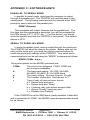
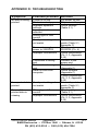
1
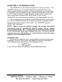
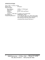
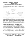
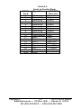
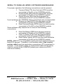
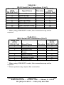
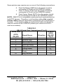
Parallel to Serial and Serial to Parallel Converter Model 232SPS2 Document No. 232SPS24595 B&B Electronics Mfg. Co. Inc. P.O. Box 1040 -- Ottawa, IL 61350 PH (815) 433-5100 -- FAX (815) 434-7094 Internet: http://www.bb-elec.com [email protected] [email protected] B&B Electronics -- June 1995 232SPS24595 Manual Cover Page B&B Electronics -- PO Box 1040 -- Ottawa, IL 61350 PH (815) 433-5100 -- FAX (815) 434-7094 Table of Contents CHAPTER 1: INTRODUCTION....................................................... 1 PACKING LIST................................................................................ 1 SPECIFICATIONS............................................................................ 2 CHAPTER 2: PARALLEL TO SERIAL INSTALLATION.............. 3 CONNECTING THE 232SPS2 TO YOUR PARALLEL PORT...... 3 CONNECTING THE 232SPS2 TO YOUR SERIAL PRINTER...... 3 CHAPTER 3: SERIAL TO PARALLEL INSTALLATION.............. 4 CONNECTING THE 232SPS2 TO YOUR PARALLEL PRINTER4 CONNECTING THE 232SPS2 TO YOUR SERIAL PORT............ 4 CHAPTER 4: POWER CONNECTIONS.......................................... 5 CHAPTER 5: SELECTING DIPSWITCH SETTINGS.................... 7 APPENDIX A: PARALLEL PORT CONNECTIONS................... A-1 APPENDIX B: SERIAL PORT CONNECTIONS......................... B-1 SERIAL TO PARALLEL MODE, HARDWARE HANDSHAKING 1 SERIAL TO PARALLEL MODE, SOFTWARE HANDSHAKING2 PARALLEL TO SERIAL MODE, HARDWARE HANDSHAKING 4 PARALLEL TO SERIAL MODE, SOFTWARE HANDSHAKING4 APPENDIX C: SOFTWARE HINTS............................................. C-1 PARALLEL TO SERIAL MODE................................................. C-1 SERIAL TO PARALLEL MODE................................................. C-1 APPENDIX D: TROUBLESHOOTING........................................ D-1 232SPS24595 Manual Table of Contents B&B Electronics -- PO Box 1040 -- Ottawa, IL 61350 PH (815) 433-5100 -- FAX (815) 434-7094 i CHAPTER 1: INTRODUCTION The 232SPS2 is a bi-directional parallel to serial converter. The 232SPS2 allows you to convert data from your parallel port to a serial communication format or to convert data from your serial port to a parallel communication format. Standard baud rates from 1200 to 115.2k with a variety of data formats can be used to match the user's serial port requirements. Both kinds of flow control, XON/XOFF and hardware handshaking, are supported by this unit. The unit may be port-powered using DTR and RTS on the serial port. If the 232SPS2 cannot be powered using the handshake lines, it may be powered using a 2.5mm jack. The 232SPS2 requires 12VDC @ 2 milliamps. NOTE: When using an external supply, the supply should be connected only to specifically labeled power inputs (power jack, terminal block, etc.). Connecting an external power supply to the handshake lines may damage the unit. Contact technical support for more information on connecting an external power supply to the handshake lines. PACKING LIST Examine the shipping carton and contents for physical damage. If damage is found, file a claim with B&B Electronics immediately. The following items should be in the shipping carton: 1. 232SPS2 unit 2. This manual If any of these items are missing contact B&B Electronics. 232SPS24595 Manual 1 B&B Electronics -- PO Box 1040 -- Ottawa, IL 61350 PH (815) 433-5100 -- FAX (815) 434-7094 SPECIFICATIONS Size: 3.8"L x 2.4"W x 0.9"H Buffer Size: 96 bytes Data Formats: Baud Rates: 1200 to 115.2k baud Data Bits: 7 or 8 Parity: Even, Odd, and None Stop Bits: 1 NOTE: 7 data bits, no parity is not supported. Handshaking: XON/XOFF, DTR Power Requirement: 7-18 Volts DC @ 2 ma. (This value does not include the power that is provided by the serial port and the power that is consumed by external devices.) 2 232SPS24595 Manual B&B Electronics -- PO Box 1040 -- Ottawa, IL 61350 PH (815) 433-5100 -- FAX (815) 434-7094 CHAPTER 2: PARALLEL TO SERIAL INSTALLATION When converting data from your parallel port to a serial communication format, position #8 of the dipswitch must be "ON". The other seven positions should be set to match the data format of your serial printer. Refer to Table 5.1 for dipswitch setting specifications. Data Flow 232PS 232SPS2 Parallel Port Serial Printer CONNECTING THE 232SPS2 TO YOUR PARALLEL PORT The 232SPS2 uses most of the available pins on the parallel port. To insure proper operation, you should use a cable that connects all 25 pins from connector to connector. B&B's Model 232AMM5 is recommended. For detailed information on which pins are connected on the parallel port, refer to Appendix A. CONNECTING THE 232SPS2 TO YOUR SERIAL PRINTER The connections required between your 232SPS2 and your serial printer depend on the type of flow control used. There are two kinds of flow control, XON/XOFF control and hardware handshaking control. Dipswitch position #4 must be "OFF" for XON/XOFF control. Dipswitch position #4 must be "ON" for DTR handshaking. For more detailed information on serial port connections, refer to Appendix B. 232SPS24595 Manual 3 B&B Electronics -- PO Box 1040 -- Ottawa, IL 61350 PH (815) 433-5100 -- FAX (815) 434-7094 CHAPTER 3: SERIAL TO PARALLEL INSTALLATION When converting data from your serial port to a parallel communication format, position #8 of the dipswitch must be "OFF". The other seven positions should be set to match the data format of your computer's serial port. Refer to Table 5.1 for dipswitch setting specifications. CONNECTING THE 232SPS2 TO YOUR PARALLEL PRINTER The 232SPS2 has a DB-25 female connector on its parallel port. Most parallel printers use a Centronics 36-pin connector. To insure proper operation, you should use a cable that connects all 25 pins from the DB-25 connector to the appropriate pins on a Centronics 36-pin connector. B&B's Model CPC is recommended. For detailed information on which pins are connected on the parallel port, refer to Appendix A. CONNECTING THE 232SPS2 TO YOUR SERIAL PORT The connections required between your 232SPS2 and your serial port depend on the type of flow control used. The type of flow control used depends on the software you are using. If you are unsure which type of flow control your software uses or if you plan to run different kinds of software, you should use a cable that connects all 9 pins from connector to connector and set the handshaking mode to be XON/XOFF control. In this mode both DTR handshaking and XON/XOFF control are used for flow control. Dipswitch position #4 should be "OFF" for XON/XOFF control. For more detailed information on serial port connections, refer to Appendix B. 4 232SPS24595 Manual B&B Electronics -- PO Box 1040 -- Ottawa, IL 61350 PH (815) 433-5100 -- FAX (815) 434-7094 CHAPTER 4: POWER CONNECTIONS The unit may be port-powered using DTR and RTS on the serial port. If the 232SPS2 cannot be powered using the handshake lines, it may be powered externally using +7 to +18 volts DC at 2 milliamps. If you are using an external supply, simply plug a 2.5 mm plug from an appropriate DC source into the power jack on the side of the 232SPS2 module. Power supplies are available through B&B. (Model 232PS is recommended.) 232SPS24595 Manual 5 B&B Electronics -- PO Box 1040 -- Ottawa, IL 61350 PH (815) 433-5100 -- FAX (815) 434-7094 CHAPTER 5: SELECTING DIPSWITCH SETTINGS The 232SPS2 is set up using an eight-position dipswitch. In order for the 232SPS2 to function properly, it must be set up to match your system's requirements. The following parameters on the 232SPS2 are set on the dipswitch: converter direction, baud rate, flow control, number of data bits, and the type of parity. Each of the parameters are briefly described below. For specific parameter settings, refer to Table 5.1. Converter direction - Can operate as a parallel to serial converter or as a serial to parallel converter. The direction is set by dipswitch position 8. Baud rate - Can be set from 1200 to 115.2k baud. The baud rate is determined by dipswitch positions 1-3. Flow control - Can be set for DTR control or XON/XOFF control. The type of flow control used is determined by dipswitch position 4. Data bits - Can be set for 7 or 8 data bits. The number of data bits is determined by dipswitch position 5. Parity - Can be enable or disabled by dipswitch position 6. If parity is enabled, dipswitch position 7 determines whether the parity is even or odd. 232SPS24595 Manual 7 B&B Electronics -- PO Box 1040 -- Ottawa, IL 61350 PH (815) 433-5100 -- FAX (815) 434-7094 Table 5.1 Setting 1200 Baud 2400 Baud 4800 Baud 9600 Baud 19.2K Baud 38.4 Baud 57.6K Baud 115.2K Baud XON/XOFF DTR control 8 Data bits 7 Data bits No parity Parity enable Even parity Odd parity Serial to Par. Par. to Serial 1 OFF ON OFF ON OFF ON OFF ON X X X X X X X X X X 2 OFF OFF ON ON OFF OFF ON ON X X X X X X X X X X DIP SWITCH POSITION 3 4 5 6 7 OFF X X X X OFF X X X X OFF X X X X OFF X X X X ON X X X X ON X X X X ON X X X X ON X X X X X OFF X X X X ON X X X X X OFF X X X X ON X X X X X OFF X X X X ON X X X X X OFF X X X X ON X X X X X X X X X X 8 X X X X X X X X X X X X X X X X OFF ON Example #1 - Parallel to Serial Mode, hardware handshaking, 9600 baud, 8 data bits, no parity Dipswitch position settings for Example #1 ("X" = don't care) 1 ON 2 ON 3 OFF 4 ON 5 OFF 6 OFF 7 X 8 ON Example #2 - Serial to Parallel Mode, XON/XOFF flow control, 2400 baud, 7 data bits, odd parity Dipswitch position settings for Example #2 1 ON 8 2 OFF 3 OFF 4 OFF 5 ON 6 ON 7 ON 8 OFF 232SPS24595 Manual B&B Electronics -- PO Box 1040 -- Ottawa, IL 61350 PH (815) 433-5100 -- FAX (815) 434-7094 APPENDIX A: PARALLEL PORT CONNECTIONS The parallel port connections for the parallel to serial and serial to parallel mode are shown in Table A-1, and Table A-2, respectively. The connections required are the same for both modes of handshaking. The error lines on the parallel port are forced to the "no error" states. If the printer is off-line, out of paper, etc., the 232SPS2 will force the busy line (Pin #11) on the parallel port high (logic "1") when in parallel to serial mode. If a error occurs in serial to parallel mode, the XOFF character will be sent or DTR will be lowered depending on type of flow control used. (NU - Indicates a signal is not used or is not “passed through”) Table A-1 Parallel to Serial Mode DB-25 Signal Name 232SPS2 Pin # Direction 1 Strobe Input 2 Data bit #0 Input 3 Data bit #1 Input 4 Data bit #2 Input 5 Data bit #3 Input 6 Data bit #4 Input 7 Data bit #5 Input 8 Data bit #6 Input 9 Data bit #7 Input 10 Acknowledge Output 11 Busy Output 12 PE "0" Output 13 SLCT “1” Output 14 Auto Feed Input (NU) 15 Error "1" Output 16 INIT Input (NU) 17 SLCT IN Input (NU) 18-25 GND 232SPS24595 Manual Appendix A A-1 B&B Electronics -- PO Box 1040 -- Ottawa, IL 61350 PH (815) 433-5100 -- FAX (815) 434-7094 DB-25 Pin # 1 2 3 4 5 6 7 8 9 10 11 12 13 14 15 16 17 18-25 Table A-2 Serial to Parallel Mode Signal Name 232SPS2 Direction Strobe Output Data bit #0 Output Data bit #1 Output Data bit #2 Output Data bit #3 Output Data bit #4 Output Data bit #5 Output Data bit #6 Output Data bit #7 Output Acknowledge Input Busy Input PE Input (NU) SLCT Input (NU) Auto Feed “1” Output Error Input (NU) INIT “1” Output SLCT IN “1” Output GND Appendix A A-2 232SPS24595 Manual B&B Electronics -- PO Box 1040 -- Ottawa, IL 61350 PH (815) 433-5100 -- FAX (815) 434-7094 APPENDIX B: SERIAL PORT CONNECTIONS The next four sections will cover the required serial port connections on the 232SPS2. Each section will list the required connections and the optional connections that some systems may require. Connections to the serial port of the 232SPS2 are made on a female DB-25 connector. SERIAL TO PARALLEL MODE, HARDWARE HANDSHAKING The serial port of the 232SPS2 module is wired as a DCE device. For proper operation the following connections must be present: 1. Transmit Data (TD) from the host (DTE) must be connected to Pin #2 on the 232SPS2 module. 2. Data Set Ready (DSR) from the host must be connected to Pin #6 on the 232SPS2 module. 3. Signal Ground (SG) from the host must be connected to Pin #7 on the 232SPS2 module. If port powering the 232SPS2, these connections are recommended: 4. Request to Send (RTS) from the host must be connected to Pin #4 on the 232SPS2 module. 5. Data Terminal Ready (DTR) from the host must be connected to Pin #20 on the 232SPS2 module. Some software may require one or more of the following connections: 6. Clear To Send (CTS) from the host should be connected to Pin #5 on the 232SPS2 module. 7. Data Carrier Detect (DCD) from the host should be connected to Pin #8 on the 232SPS2 module. NOTE: IBM PC’s (or compatible) serial ports and serial printers are both DTE devices. Therefore, a null modem cable ( like a serial printer cable!) must be used when connecting a PC’s serial port to a printer. A null modem cable or serial printer cable should not be used to connect to the 232SPS2 (unless your device is a DCE -such as a modem). 232SPS24595 Manual Appendix B B-1 B&B Electronics -- PO Box 1040 -- Ottawa, IL 61350 PH (815) 433-5100 -- FAX (815) 434-7094 SERIAL TO PARALLEL MODE, SOFTWARE HANDSHAKING For proper operation the following connections must be present: 1. Transmit Data (TD) from the host (DTE) must be connected to Pin #2 on the 232SPS2 module. 2. Receive Data (RD) from the host (DTE) must be connected to Pin #3 on the 232SPS2 module. 3. Signal Ground (SG) from the host must be connected to Pin #7 on the 232SPS2 module. If port powering the 232SPS2, these connections are recommended: 4. Request to Send (RTS) from the host must be connected to Pin #4 on the 232SPS2 module. 5. Data Terminal Ready (DTR) from t he host must be connected to Pin #20 on the 232SPS2 module. Some software may require one or more of the following connections: 6. Data Set Ready (DSR) from the host must be connected to Pin #6 on the 232SPS2 module. 7. Clear To Send (CTS) from the host should be connected to Pin #5 on the 232SPS2 module. 8. Data Carrier Detect (DCD) from the host should be connected to Pin #8 on the 232SPS2 module. NOTE: IBM PC’s (or compatible) serial ports and serial printers are both DTE devices. Therefore, a null modem cable ( like a serial printer cable!) must be used when connecting a PC’s serial port to a printer. A null modem cable or serial printer cable should not be used to connect to the 232SPS2 (unless your device is a DCE -such as a modem). B-2 Appendix B 232SPS24595 Manual B&B Electronics -- PO Box 1040 -- Ottawa, IL 61350 PH (815) 433-5100 -- FAX (815) 434-7094 TABLE B-1 DB-25 Serial Port Connections (S to P) Serial Port 232SPS2 (DTE) Signal Name Direction (DCE) DB-25S Pin # DB-25P Pin# 2 Transmit Data -----------> 2 3 Receive Data <----------3 4 Request to Send 4 5 Clear to Send <----------5** 6 Data Set Ready <----------6** 7 Signal Ground 7 8 Carrier Detect <----------8** 20 Data Terminal Ready -----------> 20 22 Ring Indicator NC * When using XON/XOFF control, this connection may not be required. TABLE B-2 DB-9 Serial Port Connections (S to P) Serial Port 232SPS2 (DTE) (DCE) DB-9S Pin# Signal Name Direction DB-25P Pin# 1 Data Carrier Detect <----------8** 2 Receive Data <----------3 3 Transmit Data -----------> 2 4 Data Terminal -----------> 20 Ready 5 Signal Ground 7 6 Data Set Ready <----------6** 7 Request to Send 4 8 Clear to Send <----------5** ** Some systems may require this connection. * When using XON/XOFF control, this connection may not be required. ** Some systems may require this connection. 232SPS24595 Manual Appendix B B-3 B&B Electronics -- PO Box 1040 -- Ottawa, IL 61350 PH (815) 433-5100 -- FAX (815) 434-7094 PARALLEL TO SERIAL MODE, HARDWARE HANDSHAKING The serial port of the 232SPS2 module is wired as a DCE device. For proper operation the following connections must be present: 1. Transmit Data (TD) from the printer (DTE) must be connected to Pin #2 on the 232SPS2 module. 2. Data Set Ready (DSR) from the printer must be connected to Pin #6 on the 232SPS2 module. 3. Signal Ground (SG) from the printer must be connected to Pin #7 on the 232SPS2 module. If port powering the 232SPS2, these connections are recommended: 4. Request to Send (RTS) from the host must be connected to Pin #4 on the 232SPS2 module. 5. Data Terminal Ready (DTR) from the host must be connected to Pin #20 on the 232SPS2 module. Some printers may require one or more of the following connections: 6. Clear To Send (CTS) from the printer should be connected to Pin #5 on the 232SPS2 module. 7. Data Carrier Detect (DCD) from the printer should be connected to Pin #8 on the 232SPS2 module. NOTE: IBM PC’s (or compatible) serial ports and serial printers are both DTE devices. Therefore, a null modem cable ( like a serial printer cable!) must be used when connecting a PC’s serial port to a printer. A null modem cable or serial printer cable should not be used to connect to the 232SPS2 (unless your device is a DCE -such as a modem). PARALLEL TO SERIAL MODE, SOFTWARE HANDSHAKING For proper operation the following connections must be present: 1. Transmit Data (TD) from the printer (DTE) must be connected to Pin #2 on the 232SPS2 module. 2. Receive (RD) from the printer must be connected to Pin #3 on the 232SPS2 module. 3. Signal Ground (SG) from the printer must be connected to Pin #7 on the 232SPS2 module. If port powering the 232SPS2, these connections are recommended: 4. Request to Send (RTS) from the host must be connected to Pin #4 on the 232SPS2 module. 5. Data Terminal Ready (DTR) from the host must be connected to Pin #20 on the 232SPS2 module. B-4 Appendix B 232SPS24595 Manual B&B Electronics -- PO Box 1040 -- Ottawa, IL 61350 PH (815) 433-5100 -- FAX (815) 434-7094 Some printers may require one or more of the following connections: 6. Data Set Ready (DSR) from the printer must be connected to Pin #6 on the 232SPS2 module. 7. Clear To Send (CTS) from the printer should be connected to Pin #5 on the 232SPS2 module. 8. Data Carrier Detect (DCD) from the printer should be connected to Pin #8 on the 232SPS2 module. NOTE: IBM PC’s (or compatible) serial ports and serial printers are both DTE devices. Therefore, a null modem cable ( like a serial printer cable!) must be used when connecting a PC’s serial port to a printer. A null modem cable or serial printer cable should not be used to connect to the 232SPS2 (unless your device is a DCE -such as a modem). TABLE B-3 DB-25 Serial Port Connections (P to S) Serial Port 232SPS2 (DCE) (DTE) Signal Name Direction DB-25P Pin # DB-25S 2 Transmit Data -----------> 2 3 Receive Data <----------3 4 Request to Send 4 5 Clear to Send <----------5** 6 Data Set Ready <----------6** 7 Signal Ground 7 8 Carrier Detect <----------8** 20 Data Terminal -----------> 20 Ready 22 Ring Indicator 22 232SPS24595 Manual Appendix B B-5 B&B Electronics -- PO Box 1040 -- Ottawa, IL 61350 PH (815) 433-5100 -- FAX (815) 434-7094 TABLE B-4 DB-9 Serial Port Connections (P to S) Serial Port 232SPS2 (DTE) (DCE) DB-9S Signal Name Direction DB-25P Pin # Pin # 1 Data Carrier Detect <----------8** 2 Receive Data <----------3 3 Transmit Data -----------> 2 4 Data Terminal -----------> 20 Ready 5 Signal Ground 7 6 Data Set Ready <----------6** 7 Request to Send 4 8 Clear to Send <----------5** * When using XON/XOFF control, this connection may not be required. ** Some printers may require this connection. B-6 Appendix B 232SPS24595 Manual B&B Electronics -- PO Box 1040 -- Ottawa, IL 61350 PH (815) 433-5100 -- FAX (815) 434-7094 APPENDIX C: SOFTWARE HINTS PARALLEL TO SERIAL MODE In parallel to serial mode, data from the computer is output through the parallel port. The 232SPS2 will send the data to the serial printer. The following command can be entered at the DOS prompt to send a data out the parallel port: PRINT filename This command will output filename out the parallel port. The first time that this command is executed, you will be prompted for the PRN device (LPT1, LPT2, etc. ). For this device, you should enter the parallel port that the 232SPS2 is connected. The default device is LPT1. SERIAL TO PARALLEL MODE In serial to parallel mode, data is output through the serial port. The 232SPS2 will send the data to the printer. Before data can be sent out the serial port, you must set up the communications to match the serial port settings of the 232SPS2. Your serial port's communications can be set using the "MODE" command as follows: MODE COMn: b,p,s,r The syntax options for the MODE command are: COMn b p s r The port to be configured. COM1, COM2 are two common examples. The baud rate setting. 12=1200, 24=2400, 48=4800, 96=9600, & 19=19200 baud The parity setting. N=none, E=even, O=odd. The number of stop bits. Must be set to "1". Type of retry of time-out error occurs. e = Return busy port error. b = Return busy port "Busy" p = Continue retry until printer accepts data r = Return "Ready" from busy port n = Disable retry (Default) If the 232SPS2 is set for 9600 baud, parity disabled, 8 data bits and is connected to COM1, the MODE command parameters would be as follows: 232SPS24595 Manual Appendix C C-1 B&B Electronics -- PO Box 1040 -- Ottawa, IL 61350 PH (815) 433-5100 -- FAX (815) 434-7094 MODE COM1: 96,n,8,1,p If any of the parameters are omitted, the most recent setting will be used. It is recommended that the "p" option be used for the retry option. If the "p" is not used, a device busy error may occur. To send data out the serial port, the following command can be entered at the DOS prompt: TYPE filename > COM1 This command will send filename out COM1. C-2 Appendix C 232SPS24595 Manual B&B Electronics -- PO Box 1040 -- Ottawa, IL 61350 PH (815) 433-5100 -- FAX (815) 434-7094 APPENDIX D: TROUBLESHOOTING Symptom Possible problem Solution No data is being printed. Printer is off-line Printer is out of paper Improper dipswitch settings Improper mode selected Wrong type of flow control Serial port settings do not match No or not enough power to 232SPS2 Improper connections Connected to wrong port Data sent out wrong port Data not sent from computer Unexpected data printed Serial port settings do not match Some of the printed data is missing Wrong type of flow control Improper connections Put printer on-line Fill printer with paper Check settings (Table 5.1) Set serial ports to match (Table 5.1, Appendix C) Check power on 232SPS2 (Ch. 4) Check connections (Ch. 2, 3, Appendix A, B) Connect to the proper port Check software (Appendix C) Check software (Appendix C) Check connections (Ch. 2, 3, Appendix A, B) Set serial ports to match (Table 5.1, Appendix C) Check settings (Table 5.1) Check connections (Ch. 2, 3, Appendix A, B) 232SPS24595 Manual Appendix D D-1 B&B Electronics -- PO Box 1040 -- Ottawa, IL 61350 PH (815) 433-5100 -- FAX (815) 434-7094 FEDERAL COMMUNICATIONS COMMISSION RADIO FREQUENCY INTERFACE STATEMENT Class A Equipment This equipment has been tested and found to comply with the limits for Class A digital device, pursuant to Part 15 of the FCC Rules. These limits are designed to provide reasonable protection against harmful interference when the equipment is operated in a commercial environment. This equipment generates, uses, and can radiate radio frequency energy and, if not installed and used in accordance with the instructions, may cause harmful interference to radio communications. Operation of this equipment in a residential area is likely to cause harmful interference, in which case the user will be required to correct the interference at personal expense. FCC Class A Equipment Statement