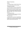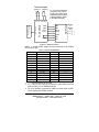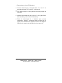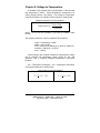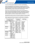
1
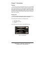
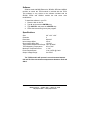
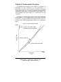
Not Recommended for New Installations.
Please contact Technical Support for more information.
K-type Thermocouple Amplifier
Model TCDA
Documentation Number TCDA0997
This product
Designed and Manufactured
In Ottawa, Illinois
USA
of domestic and imported parts by
B&B Electronics Mfg. Co. Inc.
707 Dayton Road -- P.O. Box 1040 -- Ottawa, IL 61350
PH (815) 433-5100 -- FAX (815) 433-5100
Internet:
http://www.bb-elec.com
[email protected]
[email protected]
Copyright © 1997 by B&B Electronics Mfg. Co. All rights reserved.
Documentation Number TCDA0997 Manual
Cover Page
B&B Electronics -- PO Box 1040 -- Ottawa, IL 61350
PH (815) 433-5100 -- FAX (815) 433-5104
TABLE OF CONTENTS
CHAPTER 1: INTRODUCTION ..................................................................... 1
FEATURES ......................................................................................................... 1
PACKING LIST ................................................................................................... 1
SOFTWARE ........................................................................................................ 2
SPECIFICATIONS ................................................................................................ 2
CHAPTER 2: THERMOCOUPLE OVERVIEW........................................... 3
CHAPTER 3: CONNECTIONS ....................................................................... 5
OVERVIEW ........................................................................................................ 5
THERMOCOUPLE CONNECTIONS........................................................................ 5
POWER SUPPLY CONNECTIONS ......................................................................... 5
OUTPUT CONNECTIONS ..................................................................................... 5
CHAPTER 4: CALIBRATION ........................................................................ 7
OVERVIEW ........................................................................................................ 7
CALIBRATION PROCEDURE FOR STANDARD TCDA MODULES .......................... 7
CALIBRATION PROCEDURE FOR MODIFIED TCDA MODULES ........................... 8
CHAPTER 5: VOLTAGE-TO-TEMPERATURE........................................ 11
CHAPTER 6: SOFTWARE ............................................................................ 13
INSTALLATION ................................................................................................ 13
APPENDIX A: TCDA CIRCUIT SCHEMATIC ......................................... 15
TCDA BOARD LAYOUT .................................................................................. 16
Documentation Number TCDA0997 Manual
Table of Contents
B&B Electronics -- PO Box 1040 -- Ottawa, IL 61350
PH (815) 433-5100 -- FAX (815) 433-5104
i
Chapter 1: Introduction
Features
The TCDA is a thermocouple amplifier that can be used with B&B
Electronics’ Data Acquisition modules to measure temperature using
a PC. The two channels of the TCDA support K-type thermocouples.
The amplifier has an output range of 0VDC to +5VDC. The standard
TCDA can measure temperatures between -50°C and 200°C. The
module can be modified at the factory so that a different temperature
range can be measured.
Packing List
Examine the shipping carton and contents for physical damage. If
there is any damage, contact B&B Electronics immediately.
The following items should be in the shipping carton:
1. The TCDA module.
2. This instruction module
3. 3.5” disk
If any of these items are missing, contact B&B Electronics.
Figure 1.1: TCDA module
Documentation Number TCDA0997 Manual
B&B Electronics -- PO Box 1040 -- Ottawa, IL 61350
PH (815) 433-5100 -- FAX (815) 433-5104
1
Software
Software used with B&B Electronics’ SDAXX, SPDA and ADIO12
modules to control the TCDA module is included with the TCDA.
This software is very similar to the software included with the
SDAXX, SPDA and ADIO12 module but with some minor
modifications.
To install the software in your PC:
1. Place the disk in drive A.
2. Type A: and press the <ENTER> key.
3. Type INSTALL and press the <ENTER> key.
4. Follow the instructions given by the program.
Specifications
Size:
4.8” x 2.2” x 0.9”
Channels:
2
Resolution:
20mV/°C
Input Voltage Offset:
150µV
Input Voltage Offset Drift:
1.5µV/°C
o
Temperature Measurement Range: -50 C to 200°C
0
TCDA Operating Temperature:
0 C to 70°C
Maximum Temperature Error:
+/- 3°C
Power Requirements:
12 to 16VDC @ 10mA
Output Voltage Range:
0 to 5VDC
The TCDA module will operate in an environment between
0°C and 70°C but can measure temperatures between -50°C and
200°C.
2
Documentation Number TCDA0997 Manual
B&B Electronics -- PO Box 1040 -- Ottawa, IL 61350
PH (815) 433-5100 -- FAX (815) 433-5104
Chapter 2: Thermocouple Overview
To understand the operation of the TCDA it is necessary to
understand the basic construction of the thermocouple.
A
thermocouple consists of two solid wires, composed of dissimilar
metals, joined at one end. The joining of dissimilar metals generates
a small DC voltage based on the temperature of this junction. The
TCDA amplifies this small voltage to a usable level for A/D
converters.
The output of a thermocouple does not have a linear relationship
with temperature. A close approximation for a K-type thermocouple
is 40.6µV/°C. This approximation is used with the TCDA. Figure 2.1
contains a plot of thermocouple output voltage over a temperature
range.
Figure 2.1: Thermocouple Non-linearity
0.0406
Output Voltage
( V)
Note: This plot is not to scale, and the
nonlinearity has been exagerated.
Ideal line (40.6uV/C)
Actual thermocouple output
0
0
Temperature
O
( C)
Documentation Number TCDA0997 Manual
B&B Electronics -- PO Box 1040 -- Ottawa, IL 61350
PH (815) 433-5100 -- FAX (815) 433-5104
1000
3
The error caused by the thermocouple non-linearity over the
-50°C to 200°C range is relatively small, so it is ignored in the
factory calibration of the TCDA. If more accurate readings must be
taken, the following techniques can be used:
1. If all temperatures are taken near a certain temperature,
calibrate the TCDA at that particular temperature.
2. Implement a look-up table in your software program to
correct for error.
3. Use a piece-wise linear model for your thermocouple output
to correct for error.
The terminal blocks on the TCDA and the leads of the
thermocouple bead are made from dissimilar metals. This creates a
second, unwanted thermocouple at the terminal blocks. This
unwanted thermocouple is called the cold junction. The temperature
of this cold junction will affect the results of the actual thermocouple.
The TCDA has cold junction compensation that automatically
corrects for small changes in the cold junction temperature. It is
important that nothing comes in contact with the terminal blocks or
the two external diodes near the terminal blocks as this may cause
large, rapid changes in the cold junction. The cold junction should
be kept at a constant temperature, if possible.
Different types of thermocouples are made by joining a wide
variety of metals. The TCDA is designed to amplify K-type
thermocouple only. Thermocouples have a positive(+) and a
negative(-) lead. These two leads must be connected to the correct
terminals on the TCDA module. Connections will be covered in the
next chapter.
4
Documentation Number TCDA0997 Manual
B&B Electronics -- PO Box 1040 -- Ottawa, IL 61350
PH (815) 433-5100 -- FAX (815) 433-5104
Chapter 3: Connections
Overview
This chapter will discuss the connections required to operate the
TCDA thermocouple amplifier. Connections between the A/D
converter and the TCDA should be kept as short as possible.
Thermocouple Connections
The TCDA can amplify voltage from a K-type thermocouple.
Only one thermocouple can be connected to each channel. The
thermocouple connections are made using terminal blocks. The
positive (+) lead of the thermocouple must be connected to T1+ and
the negative (-) lead to T1- (T2+ and T2- for channel 2). Make sure
that both leads of the thermocouple are connected to the same
channel. Color coding is used to designate the thermocouple’s
polarity. A K-type thermocouple’s negative lead is red, and the
positive lead is yellow. Figure 3.1 shows the thermocouple
connections.
Power Supply Connections
A 2.5mm power jack is provided on the side of the TCDA hood.
A 12VDC power supply must be connected to the 2.5mm power
jack. The 232PS is recommended (not included).
Output Connections
The amplified voltage of the thermocouple is available through a
male DB-25P connector. This connector is pin compatible with B&B
Electronics’ ADIO12 and SDAXX line of data acquisition modules.
The FBDA can also be used with the SPDA data acquisition
modules. The pinout of the TCDA is shown if Table 3.1. Figure 3.1
shows the connections required for the TCDA module.
Documentation Number TCDA0997 Manual
B&B Electronics -- PO Box 1040 -- Ottawa, IL 61350
PH (815) 433-5100 -- FAX (815) 433-5104
5
Thermocouples
red
yellow
red
yellow
channel 1 channel 2
Pin 17 and 18 are internally
connected in the TCDA to
provide +5V to REF+ in the
XXXSDAXX and XXXSPDA
modules (AGND to AGND
in the ADIO12 module).
GND
GND
TC #0
TC #1
GND
1
1
7
7
8
8
9
9
17
17
18
18
19
19
A/D Module
TCDA Module
2.5mm Power Jack
Power Supply
T1+ T1- T2+ T2GND
GND
A/D ch.
A/D ch.
+5VDC
REF+
REF-
RS-232
or
RS-485
Port
Figure 3.1: TCDA Connections
NOTE: A 12VDC power supply must be connected to the TCDA’s
2.5mm power jack.
Table 3.1: Pinout of TCDA Module
Pin #
1
2
3
4
5
6
7
8
9
10
11
12
13
Function
GND
------------------------------GND
TC # 0
TC # 1
-------------------------
Pin #
14
15
16
17
18
19
20
21
22
23
24
25
Function
------------------looped to pin 18
looped to pin 17
GND
-------------------------------------
1. ------- denotes that pin is not used.
2. Pin 17 and 18 are internally connected to each other to provide
5VDC to REF+ for the SDAXX modules.
3. Pin 19 is internally connected to GND to provide 0VDC to REFfor the SDAXX and SPDA modules.
6
Documentation Number TCDA0997 Manual
B&B Electronics -- PO Box 1040 -- Ottawa, IL 61350
PH (815) 433-5100 -- FAX (815) 433-5104
Chapter 4: Calibration
Overview
The standard TCDA module is calibrated at the factory for a
temperature range of -50°C to 200°C. With a resolution of 20mV/°C
and an offset voltage of -1.0VDC. The offset voltage shifts the
negative voltages produced at temperatures below 0°C to voltage
greater than 0VDC. The TCDA modules that have modified
temperature ranges are not calibrated at the factory. The user must
calibrate these modules. The calibration process described below is
the process used at the factory. The calibration process for a
different temperature range is similar, but the values will differ.
The non-linearity of the thermocouple over the -50°C to 200°C
range is relatively small, so it is ignored in the factory calibration
process. If you require more accurate readings, you may want to
consider using one of the techniques mentioned in Chapter 2.
Calibration Procedure for Standard TCDA Modules
During the calibration process and while measurements are
being taken, do not touch the terminal blocks or external diodes
near the terminal blocks!
Items required:
1. Small slotted screwdriver.
2. DC voltmeter with 10mV readability (0.01V).
3. Ice slurry - container (cup, glass, etc.) filled with ice and then
add water to cover ice, container of boiling water (be
careful!), or substance of known temperature that can be
used to calibrate the TCDA.
The following steps are used to calibrate channel 1 of the TCDA
module. The TCDA can operate in a temperature between 0°C and
70°C. It is a good idea to calibrate the TCDA at the same ambient
temperature that the module will be taking measurements in.
Information in parenthesis ( ) is used for channel 2 calibration.
Documentation Number TCDA0997 Manual
B&B Electronics -- PO Box 1040 -- Ottawa, IL 61350
PH (815) 433-5100 -- FAX (815) 433-5104
7
1. Remove the cover from the TCDA module.
2. Connect thermocouple to terminal blocks T1+ and T1- as
described in Chapter 3 (T2+ and T2- for channel 2).
3. Plug power supply in 2.5mm power jack and plug supply into
wall outlet.
4. Adjust P2 so that there is -1.0VDC on pin 6 or 7 of U1 (adjust P3
so that there is -1.0VDC on pin 6 or 7 of U3 for channel 2). See
Appendix A for board layout schematic.
5a. If you are using an ice slurry, place the thermocouple in the
center on the ice slurry. Wait several minutes for the ice slurry
to stabilize at 0°C. Adjust P1 so that the voltage on DB-25 pin 8
is 1.00VDC (adjust P4 so that the voltage on DB-25 pin 9 is
1.00VDC for channel 2).
5b. If you are using a container of boiling water, place the
thermocouple in the water as it begins to boil. Adjust P1 so that
the voltage on DB-25 pin 8 is 3.00VDC (adjust P4 so that the
voltage on DB-25 pin 9 is 3.00VDC for channel 2).
5c. If you are using some other substance with a known
temperature, place the thermocouple in the substance. Adjust
P1 so that the voltage on DB-25 pin 8 is equal to the calculated
value of Vout for the temperature of the substance (adjust P4 so
that the voltage on DB-25 pin 9 is the calculated value for Vout
for temperature of the substance).
Calibration Procedure for Modified TCDA Modules
The following is for modified temperature ranges only. If you
have a standard TCDA module, you can skip this section. The
procedure for calibration modified temperature ranges is similar to
the process discussed above. The modified temperature range,
values for Voff and resolution, and the modified Voltage-toTemperature Conversion Equation are included with modified TCDA
modules. Vout is the voltage on DB-25 pin 8 (DB-25 pin 9 for
channel 2) that represents temperature.
8
Documentation Number TCDA0997 Manual
B&B Electronics -- PO Box 1040 -- Ottawa, IL 61350
PH (815) 433-5100 -- FAX (815) 433-5104
1. Remove the cover from TCDA module.
2. Connect thermocouple to terminal blocks T1+ and T1- as
described in chapter 3 (T2+ and T2- for channel 2).
3.
4. Plug power supply in 2.5mm power jack and plug supply into
wall outlet.
5. Adjust P2 so that there is Voff on pin 6 or 7 of U1 (adjust P3 so
there is Voff on pin 6 or 7 of U3 for channel 2).
6. Place the thermocouple in a substance with a known
temperature. Adjust P1 so that the voltage on DB-25 pin 8 is
equal to the calculated Vout (adjust P4 so that the voltage on
DB-25 pin 9 is equal to the calculated Vout for channel 2).
Documentation Number TCDA0997 Manual
B&B Electronics -- PO Box 1040 -- Ottawa, IL 61350
PH (815) 433-5100 -- FAX (815) 433-5104
9
Chapter 5: Voltage-to-Temperature
In standard TCDA modules the low temperature is -50°C and the
high temperature is 200°C. These temperatures correspond to an
output voltage between 0 and 5VDC. The Voltage-to-Temperature
Conversion Equation for standard TCDA modules is shown below.
Voltage-to-Temperature Conversion Equation
Temperature° C =
Vout + Voff
resolution
NOTE: Do not use this equation if you have a modified TCDA
module.
The following values are used for standard TCDA modules:
-50°C < Temperature < 200°C
0VDC < Vout < 5VDC
Vout is measured on DB-25 pin 8 ( pin 9 for channel 2)
resolution = 20mV/°C = 0.02V/°C
Voff = -1.0VDC
TCDA modules with modified temperature measurement ranges
will be supplied with temperature range, values for Voff, and
resolution, and a modified Voltage-to-Temperature Conversion
Equation.
The Fahrenheit-to-Centigrade and
Conversion Equations are shown below.
Centigrade-to-Fahrenheit
C-to-F and F-to-C Conversion Equations
C=
5
× ( F − 32)
9
F=
9
× C + 32
5
Documentation Number TCDA0997 Manual
B&B Electronics -- PO Box 1040 -- Ottawa, IL 61350
PH (815) 433-5100 -- FAX (815) 433-5104
11
Chapter 6: Software
Included with the TCDA module is a diskette with software
examples written in Borland C++, Borland Pascal and Microsoft®
QuickBASIC v4.5. These DOS-based example program show how
to access the TCDA module connected to the following modules:
•
•
•
•
•
•
•
•
•
232SDA10
232SDA12
232SPDA
232SPDACL
485SDA10
485SDA12
485SPDA
485SPDACL
ADIO12
Installation
To install the example files on your hard drive:
•
•
•
•
Place the disk in drive A.
Type A: and press the <ENTER> key.
Type INSTALL and press the <ENTER> key.
Follow the instructions given by the program.
After the software installation is complete, the file, FILES.LST,
contains a list of installed files with a brief description of each. The
file, HISTORY.LST, contains a description of each revision to the
software files. The file, READ.ME, contains corrections and
additions to the printed documentation. The file, MAKEIT.BAT, in the
subdirectory for each module is an example of how to compile and
link the example program in each language. This file may need to be
modified to use the path to your compiler.
Documentation Number TCDA0997 Manual
B&B Electronics -- PO Box 1040 -- Ottawa, IL 61350
PH (815) 433-5100 -- FAX (815) 433-5104
13