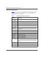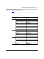
1
Release Notes for Router
Software Version 11.02
Router Software Version 11.02
Site Manager Software Version 5.02
Part No. 114093 Rev. C
June 1997
4401 Great America Parkway
Santa Clara, CA 95054
8 Federal Street
Billerica, MA 01821
Copyright © 1988–1997 Bay Networks, Inc.
All rights reserved. Printed in the USA. June 1997.
The information in this document is subject to change without notice. The statements, configurations, technical data,
and recommendations in this document are believed to be accurate and reliable, but are presented without express or
implied warranty. Users must take full responsibility for their applications of any products specified in this document.
The information in this document is proprietary to Bay Networks, Inc.
The software described in this document is furnished under a license agreement and may only be used in accordance
with the terms of that license. A summary of the Software License is included in this document.
Restricted Rights Legend
Use, duplication, or disclosure by the United States Government is subject to restrictions as set forth in subparagraph
(c)(1)(ii) of the Rights in Technical Data and Computer Software clause at DFARS 252.227-7013.
Notice for All Other Executive Agencies
Notwithstanding any other license agreement that may pertain to, or accompany the delivery of, this computer
software, the rights of the United States Government regarding its use, reproduction, and disclosure are as set forth in
the Commercial Computer Software-Restricted Rights clause at FAR 52.227-19.
Trademarks of Bay Networks, Inc.
ACE, AFN, AN, BCN, BLN, BN, BNX, CN, FN, FRE, GAME, LN, Optivity, PPX, Bay Networks, SynOptics,
SynOptics Communications, Wellfleet and the Wellfleet logo are registered trademarks and Advanced Remote Node,
ANH, ARN, ASN, BayStack, Bay•SIS, BCNX, BLNX, EZ Install, EZ Internetwork, EZ LAN, PathMan, PhonePlus,
Quick2Config, RouterMan, SPEX, Bay Networks Press, the Bay Networks logo and the SynOptics logo are
trademarks of Bay Networks, Inc.
Third-Party Trademarks
All other trademarks and registered trademarks are the property of their respective owners.
Statement of Conditions
In the interest of improving internal design, operational function, and/or reliability, Bay Networks, Inc. reserves the
right to make changes to the products described in this document without notice.
Bay Networks, Inc. does not assume any liability that may occur due to the use or application of the product(s) or
circuit layout(s) described herein.
Portions of the code in this software product are Copyright © 1988, Regents of the University of California. All rights
reserved. Redistribution and use in source and binary forms of such portions are permitted, provided that the above
copyright notice and this paragraph are duplicated in all such forms and that any documentation, advertising materials,
and other materials related to such distribution and use acknowledge that such portions of the software were
developed by the University of California, Berkeley. The name of the University may not be used to endorse or
promote products derived from such portions of the software without specific prior written permission.
SUCH PORTIONS OF THE SOFTWARE ARE PROVIDED “AS IS” AND WITHOUT ANY EXPRESS OR
IMPLIED WARRANTIES, INCLUDING, WITHOUT LIMITATION, THE IMPLIED WARRANTIES OF
MERCHANTABILITY AND FITNESS FOR A PARTICULAR PURPOSE.
In addition, the program and information contained herein are licensed only pursuant to a license agreement that
contains restrictions on use and disclosure (that may incorporate by reference certain limitations and notices imposed
by third parties).
ii
114093 Rev. C
USA Requirements Only
Federal Communications Commission (FCC) Compliance Notice: Radio Frequency Notice
This equipment generates, uses, and can radiate radio-frequency energy. If you do not install and use this equipment
according to the instruction manual, this product may interfere with radio communications. This product has been
tested and found to comply with the limits for a Class A computing device, pursuant to Subpart J of Part 15 of FCC
Rules. Operation is subject to the following two conditions: (1) this device may not cause harmful interference, and
(2) this device must accept any interference received, including interference that may cause undesired operation.
Operating this equipment in a residential area is likely to interfere with radio communications; in which case, the user,
at his/her own expense, must correct the interference.
Shielded-compliant cables must be used with this unit to ensure compliance with the Class A limits.
EN 55 022 Declaration of Conformance
This is to certify that the Bay Networks products in this book are shielded against the generation of radio interference
in accordance with the application of Council Directive 89/336/EEC, Article 4a. Conformity is declared by the
application of EN 55 022:1987 Class A (CISPR 22:1985/BS 6527:1988).
EN 55 022 Declaration of Conformance
This is to certify that the Bay Networks products in this book are shielded against the generation of radio interference
in accordance with the application of Council Directive 89/336/EEC, Article 4a. Conformity is declared by the
application of EN 55 022:1987 Class B (CISPR 22:1985/BS 6527:1988).
114093 Rev. C
iii
Japan/Nippon Requirements Only
Voluntary Control Council for Interference (VCCI) Statement
Voluntary Control Council for Interference (VCCI) Statement
This equipment is in the 1st category (information equipment to be used in commercial and/or industrial areas) and
conforms to the standards set by the Voluntary Control Council for Interference by Data Processing Equipment and
Electronic Office Machines that are aimed at preventing radio interference in commercial and/or industrial areas.
Consequently, when this equipment is used in a residential area or in an adjacent area thereto, radio interference may
be caused to equipment such as radios and TV receivers.
Compliance with the applicable regulations is dependent upon the use of shielded cables. The user is responsible for
procuring the appropriate cables. Read instructions for correct handling.
iv
114093 Rev. C
Canada Requirements Only
Canada CS-03 Rules and Regulations
Note: The Canadian Department of Communications label identifies certified equipment. The certification means that
the equipment meets certain telecommunications network protective operations and safety requirements. The
Department does not guarantee the equipment will operate to the user's satisfaction.
Before installing this equipment, users should ensure that it is permissible to be connected to the facilities of the local
telecommunications company. The equipment must also be installed using an acceptable method of connection. In
some cases, the company's inside wiring associated with a single line individual service may be extended by means of
a certified connector assembly (telephone extension cord). The customer should be aware that compliance with the
above conditions may not prevent the degradation of service in some situations.
Repairs to certified equipment should be made by an authorized Canadian maintenance facility designated by the
supplier. Any repairs or alterations made by the user to this equipment or equipment malfunctions, may give the
telecommunications company cause to request the user to disconnect the equipment.
Users should ensure for their own protection that the electrical ground connections of the power utility, telephone lines
and internal metallic water pipe system, if present, are connected together. This precaution may be particularly
important in rural areas.
Caution: Users should not attempt to make such connections themselves, but should contact the appropriate electric
inspection authority, or electrician, as appropriate.
Canada CS-03 — Règles et règlements
Note: L’étiquette du ministère des Communications du Canada indique que l’appareillage est certifié, c’est-à-dire
qu’il respecte certaines exigences de sécurité et de fonctionnement visant les réseaux de télécommunications. Le
ministère ne garantit pas que l’appareillage fonctionnera à la satisfaction de l’utilisateur.
Avant d’installer l’appareillage, s’assurer qu’il peut être branché aux installations du service de télécommunications
local. L’appareillage doit aussi être raccordé selon des méthodes acceptées. Dans certains cas, le câblage interne du
service de télécommunications utilisé pour une ligne individuelle peut être allongé au moyen d’un connecteur certifié
(prolongateur téléphonique). Le client doit toutefois prendre note qu’une telle installation n’assure pas un service
parfait en tout temps.
Les réparations de l’appareillage certifié devraient être confiées à un service d’entretien canadien désigné par le
fournisseur. En cas de réparation ou de modification effectuées par l’utilisateur ou de mauvais fonctionnement de
l’appareillage, le service de télécommunications peut demander le débranchment de l’appareillage.
Pour leur propre sécurité, les utilisateurs devraient s’assurer que les mises à la terre des lignes de distribution
d’électricité, des lignes téléphoniques et de la tuyauterie métallique interne sont raccordées ensemble. Cette mesure de
sécurité est particulièrement importante en milieu rural.
Attention: Les utilisateurs ne doivent pas procéder à ces raccordements eux-mêmes mais doivent plutôt faire appel
aux pouvoirs de réglementation en cause ou à un électricien, selon le cas.
114093 Rev. C
v
Canada Requirements Only (continued)
D. O. C. Explanatory Notes: Equipment Attachment Limitations
The Canadian Department of Communications label identifies certified equipment. This certification meets certain
telecommunication network protective, operational and safety requirements. The department does not guarantee the
equipment will operate to the users satisfaction.
Before installing the equipment, users should ensure that it is permissible to be connected to the facilities of the local
telecommunications company. The equipment must also be installed using an acceptable method of connection. In
some cases, the company’s inside wiring associated with a single line individual service may be extended by means of
a certified connector assembly (telephone extension cord). The customer should be aware that compliance with the
above condition may not prevent degradation of service in some situations.
Repairs to certified equipment should be made by an authorized Canadian maintenance facility designated by the
supplier. Any repairs or alterations made by the user to this equipment, or equipment malfunctions, may give the
telecommunications company cause to request the user to disconnect the equipment.
Users should ensure for their own protection that the electrical ground connections of the power utility, telephone lines
and internal metallic water pipe system, if present, are connected together. This precaution may be particularly
important in rural areas.
Caution: Users should not attempt to make such connections themselves, but should contact the appropriate electrical
inspection authority, or electrician, as appropriate.
Notes explicatives du ministère des Communications: limites visant les accessoires
L’étiquette du ministère des Communications du Canada indique que l’appareillage est certifié, c’est-à-dire qu’il
respecte certaines exigences de sécurité et de fonctionnement visant les réseaux de télécommunications. Le ministère
ne garantit pas que l’appareillage fonctionnera à la satisfaction de l’utilisateur.
Avant d’installer l’appareillage, s’assurer qu’il peut être branché aux installations du service de télécommunications
local. L’appareillage doit aussi être raccordé selon des méthodes acceptées. Dans certains cas, le câblage interne du
service de télécommunications utilisé pour une ligne individuelle peut être allongé au moyen d’un connecteur certifié
(prolongateur téléphonique). Le client doit toutefois prendre note qu’une telle installation n’assure pas un service
parfait en tout temps.
Les réparations de l’appareillage certifié devraient être confiées à un service d’entretien canadien désigné par le
fournisseur. En cas de réparation ou de modification effectuées par l’utilisateur ou de mauvais fonctionnement de
l’appareillage, le service de télécommunications peut demander le débranchment de l’appareillage.
Pour leur propre sécurité, les utilisateurs devraient s’assurer que les mises à la terre des lignes de distribution
d’électricité, des lignes téléphoniques et de la tuyauterie métallique interne sont raccordées ensemble. Cette mesure de
sécurité est particulièrement importante en milieu rural.
Attention: Les utilisateurs ne doivent pas procéder à ces raccordements eux-mêmes mais doivent plutôt faire appel
aux pouvoirs de réglementation en cause ou à un électricien, selon le cas.
vi
114093 Rev. C
Canada Requirements Only (continued)
Canadian Department of Communications Radio Interference Regulations
This digital apparatus (Access Feeder Node, Access Link Node, Access Node, Access Stack Node, Backbone
Concentrator Node, Backbone Concentrator Node Switch, Backbone Link Node, Backbone Link Node Switch,
Concentrator Node, Feeder Node, Link Node) does not exceed the Class A limits for radio-noise emissions from
digital apparatus as set out in the Radio Interference Regulations of the Canadian Department of Communications.
Réglement sur le brouillage radioélectrique du ministère des Communications
Cet appareil numérique (Access Feeder Node, Access Link Node, Access Node, Access Stack Node, Backbone
Concentrator Node, Backbone Concentrator Node Switch, Backbone Link Node, Backbone Link Node Switch,
Concentrator Node, Feeder Node, Link Node) respecte les limites de bruits radioélectriques visant les appareils
numériques de classe A prescrites dans le Réglement sur le brouillage radioélectrique du ministère des
Communications du Canada.
114093 Rev. C
vii
T1 Service Compliance Statements
T1 Service
NOTE:
This T1 Service notice applies to you only if you have received a single or dual port Multi-Channel T1
(MCT1) Link Module (which provides an internal CSU).
This equipment complies with Part 68 of FCC Rules. Please note the following:
1.
You are required to request T1 service from the telephone company before you connect the CSU to a T1 network.
When you request T1 service, you must provide the telephone company with the following data:
•
The Facility Interface Code
Provide the telephone company with both codes below:
—
—
04DU9-B (1.544 MB D4 framing format)
04DU9-C (1.544 MB ESF format)
The telephone company will select the code it has available.
•
•
•
The Service Order Code: 6.0F
The required USOC jack: RJ48C
The make, model number, and FCC Registration number of the CSU.
2.
Your telephone company may make changes to its facilities, equipment, operations, or procedures that could
affect the proper functioning of your equipment. The telephone company will notify you in advance of such
changes to give you an opportunity to maintain uninterrupted telephone service.
3.
If your CSU causes harm to the telephone network, the telephone company may temporarily discontinue your
service. If possible, they will notify you in advance, but if advance notice is not practical, you will be notified as
soon as possible and will be informed of your right to file a complaint with the FCC.
4.
If you experience trouble with the CSU, please contact Bay Networks Technical Response Center in your area for
service or repairs. Repairs should be performed only by service personnel authorized by Bay Networks, Inc.
United States
Valbonne, France
Sydney, Australia
Tokyo, Japan
5.
viii
1-800-2LAN-WAN
(33) 92-96-69-68
(61) 2-9927-8880
(81) 3-5402-7041
You are required to notify the telephone company when you disconnect the CSU from the network and when you
disconnect the BCNX or BLNX from the network.
114093 Rev. C
Bay Networks Software License
Note: This is Bay Networks basic license document. In the absence of a
software license agreement specifying varying terms, this license — or the
license included with the particular product — shall govern licensee’s use of
Bay Networks software.
This Software License shall govern the licensing of all software provided to licensee by Bay Networks (“Software”).
Bay Networks will provide licensee with Software in machine-readable form and related documentation
(“Documentation”). The Software provided under this license is proprietary to Bay Networks and to third parties from
whom Bay Networks has acquired license rights. Bay Networks will not grant any Software license whatsoever, either
explicitly or implicitly, except by acceptance of an order for either Software or for a Bay Networks product
(“Equipment”) that is packaged with Software. Each such license is subject to the following restrictions:
1.
Upon delivery of the Software, Bay Networks grants to licensee a personal, nontransferable, nonexclusive license
to use the Software with the Equipment with which or for which it was originally acquired, including use at any
of licensee’s facilities to which the Equipment may be transferred, for the useful life of the Equipment unless
earlier terminated by default or cancellation. Use of the Software shall be limited to such Equipment and to such
facility. Software which is licensed for use on hardware not offered by Bay Networks is not subject to restricted
use on any Equipment, however, unless otherwise specified on the Documentation, each licensed copy of such
Software may only be installed on one hardware item at any time.
2.
Licensee may use the Software with backup Equipment only if the Equipment with which or for which it was
acquired is inoperative.
3.
Licensee may make a single copy of the Software (but not firmware) for safekeeping (archives) or backup
purposes.
4.
Licensee may modify Software (but not firmware), or combine it with other software, subject to the provision
that those portions of the resulting software which incorporate Software are subject to the restrictions of this
license. Licensee shall not make the resulting software available for use by any third party.
5.
Neither title nor ownership to Software passes to licensee.
6.
Licensee shall not provide, or otherwise make available, any Software, in whole or in part, in any form, to any
third party. Third parties do not include consultants, subcontractors, or agents of licensee who have licensee’s
permission to use the Software at licensee’s facility, and who have agreed in writing to use the Software only in
accordance with the restrictions of this license.
7.
Third-party owners from whom Bay Networks has acquired license rights to software that is incorporated into
Bay Networks products shall have the right to enforce the provisions of this license against licensee.
8.
Licensee shall not remove or obscure any copyright, patent, trademark, trade secret, or similar intellectual
property or restricted rights notice within or affixed to any Software and shall reproduce and affix such notice on
any backup copy of Software or copies of software resulting from modification or combination performed by
licensee as permitted by this license.
114093 Rev. C
ix
Bay Networks Software License (continued)
9.
Licensee shall not reverse assemble, reverse compile, or in any way reverse engineer the Software. [Note: For
licensees in the European Community, the Software Directive dated 14 May 1991 (as may be amended from time
to time) shall apply for interoperability purposes. Licensee must notify Bay Networks in writing of any such
intended examination of the Software and Bay Networks may provide review and assistance.]
10. Notwithstanding any foregoing terms to the contrary, if licensee licenses the Bay Networks product “Site
Manager,” licensee may duplicate and install the Site Manager product as specified in the Documentation. This
right is granted solely as necessary for use of Site Manager on hardware installed with licensee’s network.
11. This license will automatically terminate upon improper handling of Software, such as by disclosure, or Bay
Networks may terminate this license by written notice to licensee if licensee fails to comply with any of the
material provisions of this license and fails to cure such failure within thirty (30) days after the receipt of written
notice from Bay Networks. Upon termination of this license, licensee shall discontinue all use of the Software
and return the Software and Documentation, including all copies, to Bay Networks.
12. Licensee’s obligations under this license shall survive expiration or termination of this license.
x
114093 Rev. C
Contents
Preface
Conventions ..................................................................................................................... xv
Ordering Bay Networks Publications ............................................................................... xv
Bay Networks Customer Service .....................................................................................xvi
How to Get Help ..............................................................................................................xvi
For More Information ......................................................................................................xvii
Release Notes for
Router Software Version 11.02
Upgrading to Version 11.02 ............................................................................................... 2
New Features .................................................................................................................... 2
ATM Per-VC Clipping .................................................................................................. 2
Bay Command Console (BCC) ................................................................................... 2
Platform Requirements ......................................................................................... 3
Configuring Protocols, Interfaces, and Link Modules ........................................... 3
Bisynchronous (Bisync) Over TCP on ARN Platforms ................................................ 5
Dial Services ............................................................................................................... 6
AT Modem Command Set .................................................................................... 6
Frame Relay Dial-on-Demand .............................................................................. 6
BAP ...................................................................................................................... 6
X.25 Over D Channel for BRI Service .................................................................. 6
Data Link Switching (DLSw) ........................................................................................ 7
Simplified Site Manager User Interface ................................................................ 7
SNA PU Type 1 Support ....................................................................................... 8
DLSw Version 2 Support ....................................................................................... 8
DLSw Backup Peers ............................................................................................. 9
Equal Cost Multipath (ECMP) ..................................................................................... 9
RADIUS Client: Authentication and Accounting .......................................................... 9
X.25 Address Insertion .............................................................................................. 10
X.25 Over the ISDN D Channel ................................................................................ 10
114093 Rev. C
xi
New Hardware Products ........................................................................................... 10
Data Collection Modules for the ARN ................................................................. 10
QMCT1 w/DS0A Link Module ............................................................................. 11
Guidelines for Using Version 11.02 .................................................................................. 11
ARN Guidelines ......................................................................................................... 11
ARN Memory Requirements ............................................................................... 11
Using the Technician Interface ARN Installation Script ....................................... 11
Cycling Power to the ARN .................................................................................. 12
Using the Technician Interface Packet Capture Script on an ARN ..................... 12
Memory Allocation on ARN Routers ................................................................... 12
ARN DCM Dependencies ......................................................................................... 13
DCM Hardware Dependencies for the ARN Router ........................................... 13
DCM Software Image and Router Software Compatibility .................................. 14
Changing RMON DCM Configurations ............................................................... 14
Configuring Ethernet with DCM Interfaces on an ARN ....................................... 14
Recommendations for ATM Signaling Parameters .................................................... 15
Network Booting on DSU/CSU Interfaces ................................................................. 15
Using the BCC .......................................................................................................... 15
Configuring NTP Using the Technician Interface ....................................................... 16
Support for Banyan 80C4 ISAP ................................................................................ 16
Setting Modem Initialization Strings Using the Technician Interface ......................... 16
Changing the PPP MRU Setting for Routers Running Software
Versions 11.02 and Earlier ........................................................................................ 17
ISP Mode Support ..................................................................................................... 17
Protocols Supported ........................................................................................................ 17
Standards Supported ...................................................................................................... 20
Flash Memory Cards Supported ..................................................................................... 25
xii
114093 Rev. C
Tables
Table 1.
Table 2.
Table 3.
Table 4.
114093 Rev. C
ARN Module Numbers for packet.bat ....................................................... 12
Settings for ATM Signaling Parameters .................................................... 15
Standards Supported by Version 11.02 .................................................... 20
Approved Flash Memory Cards ................................................................ 25
xiii
Preface
If you are responsible for configuring, managing, or upgrading Bay Networks®
routers, read this document.
Conventions
bold text
Indicates text that you need to enter, command names,
and buttons in menu paths.
Example: Enter wfsm &
Example: Use the dinfo command.
Example: ATM DXI > Interfaces > PVCs identifies the
PVCs button in the window that appears when you
select the Interfaces option from the ATM DXI menu.
italic text
Indicates variable values in command syntax
descriptions, new terms, file and directory names, and
book titles.
screen text
Indicates data that appears on the screen.
Example: Set Bay Networks Trap Monitor Filters
Ordering Bay Networks Publications
To purchase additional copies of this document or other Bay Networks
publications, order by part number from Bay Networks Press™ at the following
numbers:
114093 Rev. C
•
Phone--U.S./Canada: 1-888-422-9773
•
Phone--International: 1-510-490-4752
•
FAX--U.S./Canada and International: 1-510-498-2609
xv
Release Notes for Router Software Version 11.02
Bay Networks Customer Service
You can purchase a support contract from your Bay Networks distributor or
authorized reseller, or directly from Bay Networks Services. For information
about, or to purchase a Bay Networks service contract, either call your local Bay
Networks field sales office or one of the following numbers:
Region
Telephone number
Fax number
United States and
Canada
1-800-2LANWAN; then enter Express
Routing Code (ERC) 290, when prompted,
to purchase or renew a service contract
1-508-670-8766
1-508-916-8880 (direct)
Europe
33-4-92-96-69-66
33-4-92-96-69-96
Asia/Pacific
61-2-9927-8888
61-2-9927-8899
Latin America
561-988-7661
561-988-7550
How to Get Help
If you purchased a service contract for your Bay Networks product from a
distributor or authorized reseller, contact the technical support staff for that
distributor or reseller for assistance.
If you purchased a Bay Networks service program, call one of the following Bay
Networks technical response centers:
xvi
Technical Response Center Telephone number
Fax number
Billerica, MA
1-800-2LANWAN
508-670-8765
Santa Clara, CA
1-800-2LANWAN
408-495-1188
Valbonne, France
33-4-92-96-69-68
33-4-92-96-69-98
Sydney, Australia
61-2-9927-8800
61-2-9927-8811
Tokyo, Japan
81-3-5402-0180
81-3-5402-0173
114093 Rev. C
Preface
For More Information
For information about Bay Networks and its products, visit the Bay Networks
Worldwide Web (WWW) site at http://www.baynetworks.com. To learn more
about Bay Networks Customer Service, select Customer Service on the opening
web page.
114093 Rev. C
xvii
Release Notes for
Router Software Version 11.02
This document contains the latest information about Bay Networks®
Router Software Version 11.02.
These release notes include information about
114093 Rev. C
•
Upgrading to Version 11.02
•
New Features
•
Guidelines for Using Version 11.02
•
Protocols Supported
•
Standards Supported
•
Flash Memory Cards Supported
1
Release Notes for Router Software Version 11.02
Upgrading to Version 11.02
To upgrade your router software to Version 11.02, or to upgrade your Site
Manager software to Version 5.02, refer to Upgrading Routers from Version
7-10.xx to Version 11.0 for instructions and also to the Documentation Changes
Notice for Router Version 11.02 and Site Manager Version 5.02 for supplemental
information. Your upgrade package contains these documents.
New Features
Bay Networks has implemented the following new features in the router software
for Version 11.02.
ATM Per-VC Clipping
This added ATM traffic shaping capability allows clipping on a per-VC basis. This
capability clips only VCs that fall outside of a predetermined range while allowing
other VCs to continue operating normally.
Bay Command Console (BCC)
With Version 11.02, you can now use the BCC™ to configure AN® and ANH®
routers, in addition to configuring BLN® and BCN® routers.
Version 11.01 of the router software introduced the first phase of the BCC -- a new
command line interface for Bay Networks devices.
Since this is a trial version of the BCC and we expect the interface to evolve and
expand substantially, we are not documenting the current BCC commands in our
protocol-specific documentation.
If you want to try the BCC interface, first read about the platform requirements
and the list of protocols, interfaces, and link modules you can configure. For
information about using the BCC, see “Guidelines for Using Version 11.02” later
in these release notes.
2
114093 Rev. C
Release Notes for Router Software Version 11.02
Platform Requirements
With the BayRS 11.02 release, the BCC can run on AN and BN platforms
configured with 8 MB of dynamic RAM (DRAM). The BCC also requires 1.5 MB
of free memory space to start on a slot. If you attempt to start the BCC with
insufficient DRAM or free memory on a slot, the BCC returns an error message. If
you receive an error message from BCC, you can use Site Manager to create,
modify, and view the AN or BN configurations.
Refer to the following list for specific platform and memory guidelines:
•
On AN platforms, you cannot
-- Enable or disable DCM daughterboards or hub functionality.
-- Configure ISDN or DSU/CSU functionality.
•
On BN platforms, you can run the BCC on the Fast Routing Engine (FRE®
and FRE-2), but not on the Advanced Routing Engine (ARE).
•
You can check memory usage by entering the show memory command
before and after starting the BCC on a slot.
Configuring Protocols, Interfaces, and Link Modules
You can use BCC commands to configure the following protocols, interfaces, and
link modules:
Global Protocols
114093 Rev. C
•
IP (including access policies)
•
ARP
•
IGMP
•
OSPF (including accept and announce policies)
•
BGP (including accept and announce policies)
•
Telnet (server and client)
•
TFTP
•
FTP
•
NTP
•
SNMP
3
Release Notes for Router Software Version 11.02
Interface Protocols
•
IP
•
ARP
•
RIP
•
OSPF
•
Router Discovery (RDISC)
•
Wellfleet Standard Point-to-Point
•
PPP (multilink currently not supported)
Interfaces (see also the list of link modules supporting these interface types)
•
Console
•
Ethernet
•
Token ring
•
Synchronous
•
FDDI
•
HSSI
•
Virtual
Link Modules
Module ID
wfName
Description
40
dst416
Model 5740 Dual Sync with Token Ring
80
sync
Model 5280 Quad Sync
118
sse
Model 5410 Single Sync with Ethernet
132
enet3
Model 5505 Dual Ethernet
162
qenf
Model 5450 Quad Ethernet without hardware filters
164
qef
Model 5950 Quad Ethernet with hardware filters
176
dtok
Model 5710 Dual Token Ring
192
wffddi2m
Model 5930 Multimode FDDI
193
wffddi1m
Model 5943 Hybrid FDDI with single mode on
connector B
(continued)
4
114093 Rev. C
Release Notes for Router Software Version 11.02
Module ID
wfName
Description
194
wffddi2s
Model 5940 Single Mode FDDI
195
wffddi1s
Model 5942 Hybrid FDDI with single mode on
connector A
196
wffddi2mf
Model 5946 Multi FDDI with hardware filters
197
wffddi1mf
Model 5949 Hybrid FDDI with hardware filters and
single mode on connector B
198
wffddi2sf
Model 5947 Single Mode FDDI with hardware filters
199
wffddi1sf
Model 5948 Hybrid FDDI with hardware filters and
single mode on connector A
225
shssi
Model 5295 HSSI
232
esafnf
Model 5431 Dual Sync Dual Ethernet without hardware
filters
236
esaf
Model 5531 Dual Sync Dual Ethernet with 2-CAM filters
and
Model 5532 Dual Sync Dual Ethernet with 6-CAM filters
256
qtok
Model 50021 Quad Token Ring
4352
osync
Model 5008 Octal Sync
4353
comp
Octal Sync with 32-context compression daughterboard
4354
comp128
Model AG2104038 Octal Sync with 128-context
compression daughterboard
4864
de100
Model 50038 100BASE-T Ethernet
After you use the BCC, we welcome your feedback. Please visit the BCC Web
Site at the following URL, where you can leave us a message:
http://support.baynetworks.com/library/tpubs/bccfeedbk
Bisynchronous (Bisync) Over TCP on ARN Platforms
Bisync over TCP (BOT) is now supported on the Advanced Remote Node™
(ARN™) using the Tri-Serial, Ethernet/Tri-Serial, and the Token Ring/Tri-Serial
Expansion Modules.
114093 Rev. C
5
Release Notes for Router Software Version 11.02
Dial Services
We have added the following new features to the dial services software. For
information about how to use these features, refer to Configuring Dial Services.
AT Modem Command Set
Version 11.02 supports the Hayes AT Modem commands. These commands allow
the use of a wide variety of internal and external modems. Support includes the
commands required to configure and run asynchronous PPP across modem lines.
Frame Relay Dial-on-Demand
Version 11.02 supports Frame Relay dial-on-demand. With this support, you can
use dial-on-demand to access a Frame Relay network on an “as needed” basis,
eliminating the need for expensive leased lines.
BAP
Version 11.02 supports the Bandwidth Allocation Protocol (BAP) over ISDN. For
PPP connections across ISDN lines, you can use BAP to dynamically allocate
bandwidth for a multilink bundle. BAP works together with
bandwidth-on-demand.
X.25 Over D Channel for BRI Service
Version 11.02 supports using the ISDN D channel to send X.25 packets across a
network.
6
114093 Rev. C
Release Notes for Router Software Version 11.02
Data Link Switching (DLSw)
Version 11.02 adds the following DLSw features:
•
Simplified Site Manager user interface to DLSw
•
SNA PU Type 1 support
•
DLSw Version 2
•
DLSw backup peers
Simplified Site Manager User Interface
Version 11.02 simplifies the Site Manager user interface to DLSw. This simplified
interface reduces the number of screens initially used to configure DLSw,
allowing you to provide faster network definitions for LAN and Frame Relay
interfaces, as well as
•
Reduce the number of common configuration errors
•
Simplify problem determination when troubleshooting a DLSw network
•
Provide more consistency when configuring DLSw on different types of
interfaces
When configuring a LAN interface for the first time, DLSw now requests two
screens of information:
•
DLSw Basic Global Configuration -- Enables you to specify all global
parameters from all subsystems, as well as add a single Peer IP Table entry
•
DLSw Basic Interface Configuration -- Enables you to specify all relevant
interface-related parameters for subsystems
In addition, infrequently used parameters have been removed from the global
screens, and several windows have been eliminated or clarified. Refer to
Configuring DLSw Services for more information.
114093 Rev. C
7
Release Notes for Router Software Version 11.02
SNA PU Type 1 Support
Version 11.02 supports PU Type 1 SDLC-attached controllers (such as the IBM
5294 and 5394) in a DLSw network using a single SDLC line. This functionality
can save the cost of upgrading to the newer IBM 5494 (PU Type 2.1) AS/400
controllers.
To configure an SDLC-attached PU 1 device, users must set the following
parameters in Site Manager:
•
PU Type -- Set to TYPE1
•
XID Format -- Set to VARIABLE1
For more information about setting the PU Type and XID format, refer to
Configuring DLSw Services.
DLSw Version 2 Support
Version 11.02 supports DLSw Version 2, extending the original implementation
(RFC 1434) and the subsequent DLSw Version 1 (RFC 1795). Intended for large
networks, the Version 2 subset increases network scalability and provides the
following enhancements:
•
Transmission of UDP explorer frames
•
Single TCP/IP connection
You can manage peer types by configuring them as UDP, TCP, or Unknown peers.
A router that you configure for DLSw Version 2 can also communicate with
routers running RFC 1434 and RFC 1795 implementations.
Version 11.02 does not support the DLSw Version 2 IP multicasting feature.
8
114093 Rev. C
Release Notes for Router Software Version 11.02
DLSw Backup Peers
DLSw backup peers enable users to define an alternate IP destination address
when the primary peer becomes unavailable or is unreachable. This feature
increases network availability for mission-critical IBM customers.
If a DLSw session with a remote (primary) peer fails, DLSw initiates a new
connection with a specified backup peer. Configuring a backup peer provides
•
Higher network availability -- A backup peers increases overall network
uptime.
•
Reduced cost for backup -- By defining backup peers to use dial lines, the
backup circuit is used only when session traffic exists.
•
Improved problem determination and resolution -- Traffic takes the primary
path if available, and uses the secondary path only if the primary is not
available.
Version 11.02/5.02 supports DLSw backup peers only for routers running
RFC 1434 and RFC 1795 implementations. For more information about DLSw
backup peers, refer to Configuring DLSw Services.
Equal Cost Multipath (ECMP)
Version 11.02/5.02 now supports ECMP enhancements to RIP and OSPF. ECMP
provides the ability to simultaneously forward traffic, intended for the same
location, over multiple network paths (up to five) and using the same routing cost.
RADIUS Client: Authentication and Accounting
Version 11.02/5.02 now provides Remote Authentication Dial-in User Service
(RADIUS) authentication and accounting. RADIUS defines an open and scalable
systems approach to security, billing, and usage control. By using a central
authentication server, RADIUS simplifies the security process by authenticating
users against a UNIX password file, Network Information Service (NIS), or
RADIUS database. In addition to authenticating users, RADIUS provides
accounting information (statistics) for each call the RADIUS client receives.
114093 Rev. C
9
Release Notes for Router Software Version 11.02
X.25 Address Insertion
Incoming X.25 calls that do not contain a called X.121 address are assigned to the
first SVC mapping entry and use the destination X.121 address associated with
that entry.
X.25 Over the ISDN D Channel
Version 11.02 supports X.25 over the ISDN D channel. This feature allows the
router to transport X.25 packets without incurring the expense of a leased line.
You can use the ISDN line for normal switched service applications as well as for
X.25 traffic.
The Bay Networks implementation of X.25 over the ISDN D channel is based on
ITU-T (formerly CCITT) recommendation X.31. Bay Networks has tested and
supports X.25 over the ISDN D channel in the following countries:
•
France
•
Germany
•
Spain
•
Switzerland
For information about X.25 over the ISDN D channel, refer to the Documentation
Changes Notice for Router Version 11.02 and Site Manager Version 5.02.
New Hardware Products
This section describes new hardware products that support Release 11.02/5.02.
Data Collection Modules for the ARN
Version 11.02/5.02 supports up to two optional Ethernet data collection modules
(DCMs) for the ARN -- one for the Ethernet interface on the base module and one
for the Ethernet interface on the expansion module.
Before installing a DCM, refer to “ARN DCM Dependencies” later in these
release notes for supplemental information. Refer to the Documentation Changes
Notice for Router Version 11.02 and Site Manager Version 5.02 for boot and
diagnostic PROM upgrade information, and to Installing an Ethernet RMON
DCM in a BayStack ARN Router for installation instructions.
10
114093 Rev. C
Release Notes for Router Software Version 11.02
QMCT1 w/DS0A Link Module
The QMCT1 w/DS0A link module supports the DS0A subrate frame format
standard, which enables the interface to support SDLC traffic at live speeds of
9.6 Kb/s and 19.2 Kb/s. This link module also supports DS0 to T1 speeds. Refer to
Configuring WAN Line Services for information about how to configure the
QMCT1 link module.
Guidelines for Using Version 11.02
Note the following guidelines when using Version 11.02.
ARN Guidelines
The following sections provide specific guidelines for using the ARN.
ARN Memory Requirements
The following features require a minimum DRAM configuration of 8 MB:
•
DLSw
•
ISDN BRI
•
Token ring base or expansion module configurations
Using the Technician Interface ARN Installation Script
You can use the inst_arn.bat script from a Technician Interface prompt on the
router to configure all except the following ARN interfaces:
•
V.34 modem adapter module
•
ISDN U adapter module
•
ISDN S/T adapter module
Refer to Installing and Operating BayStack ARN Routers for information about
using the ARN installation script Quick-Start procedure.
114093 Rev. C
11
Release Notes for Router Software Version 11.02
Cycling Power to the ARN
To ensure a complete power cycle, we recommend that you wait at least 4 seconds
between turning off the ARN and turning it back on.
Caution: Cycling power to the ARN too quickly could cause an error.
Using the Technician Interface Packet Capture Script on an ARN
The Technician Interface Packet Capture script (packet.bat) now prompts for the
module number of the interface on a BayStack ARN. Enter the appropriate
module number from Table 1, except for synchronous interfaces, where the
module number should always be 1.
Table 1.
ARN Module Numbers for packet.bat
ARN Interface
Technician Interface
Module Number
Base module (XCVR1 or TOKEN1)
1
First WAN adapter module interface
(COM1 or ISDN1)
2
Second WAN adapter module interface
(COM2 or ISDN2)
3
Expansion module interface
(XCVR2, TOKEN2, or COM3-5)
4
Note: For all synchronous interfaces, enter module number 1. For serial
interfaces that are configured for other WAN services (for example, BOT or
ISDN interfaces), enter the actual module number (2 or 3).
Memory Allocation on ARN Routers
Although you can change the default memory allocation on other Bay Networks
router platforms, this “buffer carving” feature is not currently supported on the
ARN platform.
12
114093 Rev. C
Release Notes for Router Software Version 11.02
On the ARN, Site Manager does not support the Admin > Kernel Configuration
option, and the Technician Interface does not support set commands for
wfKernCfgParamEntry objects. Attempting to set wfKernCfgParamGlobMem on
the ARN results in a warning message.
ARN DCM Dependencies
The following sections describe various dependencies associated with using the
ARN DCM.
DCM Hardware Dependencies for the ARN Router
The DCM board that you install in the ARN router must be revision D or E or
later, depending on the part number on DCM boards. The part numbers for
supported DCM boards are
•
920-394-D
•
920-561-E
•
920-562-D
These part numbers correspond to DCM boards that use different types of flash
(Intel or Atmel) modules. The part number of the DCM board that ships with the
ARN router is 920-562-D.
To determine the hardware revision of a DCM board installed on an ARN router
running software version 11.00 or later, perform the following steps from the
Technician Interface:
1.
Enter the following command to get the instance ID of the DCM entry:
[1:TN]$ list -i wfDCMEntry
The Technician Interface displays the instance ID.
inst_ids
2.
= 1
Enter the following command, appending the instance ID to it:
[1:TN]$ get wfDCMEntry.wfDCMhwRev.1
The Technician Interface displays the hardware revision of the DCM board.
wfDCMEntry.wfDCMhwRev.1 = "C"
114093 Rev. C
13
Release Notes for Router Software Version 11.02
DCM Software Image and Router Software Compatibility
Router Software Version 11.02 ships with the Version 1.4.1 DCM software image.
The Version 1.4.1 DCM software image is backwards-compatible with Router
Software Versions 9.0x and 10.0x.
To run RMON on an ARN router, you must upgrade the DCM software image to
Version 1.4.1 and the router software image to version 11.02.
If you have an AN or ANH router running router software version 11.00 or later,
we also recommend that you upgrade to the Version 1.4.1 DCM software image.
Before you attempt to upgrade a router to Version 11.02, we recommend that you
first check the DCM software version residing on the Ethernet DCM.
Determining the DCM Software Image Version
Enter the following command from the Technician Interface to determine the
DCM software image version:
[1:1]$ get wfDCMmw.wfDCMAgentImageVersion.0
The Technician Interface generates a message similar to the following:
wfDCMmw.wfDCMAgentImageVersion.0 = "V1.4.1"
Upgrading the DCM Software Image
Refer to the Documentation Changes Notice for Router Version 11.02 and Site
Manager Version 5.02 for instructions on loading the latest version of the DCM
software image.
Changing RMON DCM Configurations
You must disable and then reenable the DCM software on an AN, ANH, or ARN
router after setting related MIB variables.
Configuring Ethernet with DCM Interfaces on an ARN
To ensure proper DCM operation, you must configure any Ethernet w/DCM
interfaces as the first, second, or third circuit on the ARN. We recommend that you
configure the Ethernet w/DCM interfaces before you configure any other
interfaces on the device.
14
114093 Rev. C
Release Notes for Router Software Version 11.02
Recommendations for ATM Signaling Parameters
When using an ATM link module with an 8-MB ATM Routing Engine (ARE), we
recommend that you modify the parameters in Table 2 to best use memory
allocation.
Table 2.
Settings for ATM Signaling Parameters
Parameter
Recommended Setting
Max Number of SVC Applications
20
Max Point to Multipoint Connections
40
Network Booting on DSU/CSU Interfaces
AN and ANH DSU/CSU interfaces do not support network booting in Version
11.02. The ARN DSU/CSU supports network booting only over interfaces
configured for 56-Kb/s DDS service.
Using the BCC
Before entering the BCC initialization command (bcc-trial) at the Technician
Interface prompt of a BN, AN, or ANH router, back up your existing configuration
files to another location.
Caution: BCC configuration and source commands make immediate changes
to the active device configuration. Read about the source command in Using
the Bay Command Console.
After starting the BCC, enter help at the bcc> prompt for initial instructions. You
can obtain online help for different types of information (lists of configurable
objects, attributes, and attribute values; current attribute values; configuration
data; and so on). For details on how to use the BCC interface, refer to Using the
Bay Command Console. Refer also to the Documentation Changes Notice for
Router Version 11.02 and Site Manager Version 5.02.
114093 Rev. C
15
Release Notes for Router Software Version 11.02
Configuring NTP Using the Technician Interface
When you use the Technician Interface to configure the Network Time Protocol
(NTP), you must configure NTP on each slot on the router to ensure that NTP
initializes correctly.
You can configure NTP on each slot by setting the following MIB variable from
the Technician Interface:
set wfProtocols.wfNTPLoad.0 0xffffffff
commit
Support for Banyan 80C4 ISAP
Bay Networks routers now support the Banyan 80C4 ISAP on Ethernet.
Setting Modem Initialization Strings Using the Technician Interface
Several AT modem commands contain a dollar sign ($) or backslash (\). The
Technician Interface uses the $ to reference a variable and the \ to prevent the
substitution of a variable. If one of these symbols appears in the
wfModemEntry.wfModemCfgInitString initialization command, the Technician
Interface does not set the string. For example:
[1:1]$ get wfModemEntry.wfModemCfgInitString.1.2
wfModemEntry.wfModemCfgInitString.1.2 = "ATF"
[1:1]$ set wfModemEntry.wfModemCfgInitString.1.2 "AT$SB64000";commit
Variable: Undefined Variable - SB64000
The Technician Interface interprets the command as containing an undefined
variable and does not change the MIB value.
To set the MIB variable, you must add a backslash (\) in front of the symbol
causing the confusion (that is, the $ or \). For example:
[1:1]$ get wfModemEntry.wfModemCfgInitString.1.2
wfModemEntry.wfModemCfgInitString.1.2 = "ATF"
[1:1]$ set wfModemEntry.wfModemCfgInitString.1.2 "AT\$SB64000";commit
16
114093 Rev. C
Release Notes for Router Software Version 11.02
Changing the PPP MRU Setting for Routers Running Software
Versions 11.02 and Earlier
For Version 11.02, we changed the PPP default MRU value for switched services
from 1590 bytes to 1500 bytes. If you have a network with both 11.02 and
pre-11.02 Bay Networks routers, or Bay Corporate LAN Access Module
(CLAM™) routers configured with dial-on-demand, standby, dial backup, or
bandwidth-on-demand circuits, make sure that the value you set for the PPP MRU
parameter is the same for the central-site router and the remote-site routers.
Refer to the Documentation Changes Notice for Router Version 11.02 and Site
Manager Version 5.02 for details.
ISP Mode Support
Version 11.02 does not fully support ISP mode. Do not set the ISP Mode
parameter to anything other than the default. Do not enable this parameter without
direction from Bay Networks Customer Service. Bay Networks will support this
feature only for customers directed to enable it by Customer Service.
Protocols Supported
Router Software Version 11.02 supports the following bridging/routing protocols
and router configuration features:
114093 Rev. C
•
AppleTalk and AppleTalk Update-based Routing Protocol (AURP)
•
Advanced Peer-to-Peer Networking (APPN)
•
Asynchronous transfer mode (ATM)
•
ATM Data Exchange Interface (ATMDXI)
•
ATM LAN Emulation (802.3 and 802.5)
•
Bandwidth Allocation Protocol (BAP)
•
Binary Synchronous Communication Type 3 (BSC3)
•
Bootstrap Protocol (BOOTP)
•
Border Gateway Protocol (BGP-3 and BGP-4)
•
Bisync over TCP (BOT)
17
Release Notes for Router Software Version 11.02
18
•
Classless interdomain routing (CIDR)
•
Data compression
•
Data link switching (DLSw)
•
DECnet Phase IV Routing Protocol
•
Distance Vector Multicast Routing Protocol (DVMRP)
•
Dynamic Host Configuration Protocol (DHCP)
•
Exterior Gateway Protocol-2 (EGP-2)
•
Frame Relay
•
File Transfer Protocol (FTP)
•
HP Probe Protocol
•
Integrated Services Digital Network (ISDN)
•
Interface redundancy
•
Internet Gateway Management Protocol (IGMP)
•
Internet Protocol (IP)
•
Internet Control Message Protocol (ICMP)
•
Internet Packet Exchange (IPX) Protocol
•
Internet Stream Protocol (ST2)
•
Learning Bridge Protocol
•
Logical Link Control 2 (LLC2) Protocol
•
Native Mode LAN (NML) Protocol
•
Network Core Protocol
•
Network Time Protocol (NTP)
•
Open Shortest Path First (OSPF) Protocol
•
Open Systems Interconnection (OSI) Routing Protocol
•
Point-to-Point Protocol (PPP)
•
Protocol prioritization
•
Qualified Logical Link Control (QLLC)
•
Remote Authentication Dial-In User Service (RADIUS)
114093 Rev. C
Release Notes for Router Software Version 11.02
114093 Rev. C
•
RaiseDTR dialup
•
Routing Information Protocol (RIP)
•
Router discovery
•
Router redundancy
•
Service Advertisement Protocol (SAP)
•
Simple Network Management Protocol (SNMP)
•
Source Routing Bridge Protocol
•
Spanning Tree Protocol
•
Switched multimegabit data service (SMDS)
•
Synchronous Data Link Control (SDLC)
•
Telnet Protocol (Inbound and Outbound)
•
Transmission Control Protocol (TCP)
•
Transparent Bridge
•
Transparent-to-Source Routing Translation Bridge
•
Trivial File Transfer Protocol (TFTP)
•
V.25BIS dialup
•
Virtual Networking System (VINES)
•
X.25 Protocol
•
XMODEM and YMODEM Protocols
•
Xerox Network Systems (XNS) Protocol
19
Release Notes for Router Software Version 11.02
Standards Supported
Table 3 lists the request for comments (RFCs) and other standards documents
with which Version 11.02 complies. Version 11.02 may support additional
standards that are not listed in this table.
Table 3.
Standards Supported by Version 11.02
Standard
Description
ANSI
T1.107b-1991
Digital Hierarchy - Supplement to formats specifications
ANSI T1.404
DS3 Metallic Interface Specification
ANSI X3t9.5
Fiber Distributed Data Interface (FDDI)
Bellcore FR-440
Transport Systems Generic Requirements (TSGR)
Bellcore
TR-TSY-000009
Asynchronous Digital Multiplexes, Requirements and Objectives
Bellcore
TR-TSY-000010
Synchronous DS3 Add-Drop Multiplex (ADM 3/X) Requirements
and Objectives
IEEE 802.1
Logical Link Control (LLC)
IEEE 802.3
Carrier Sense Multiple Access with Collision Detection (CSMA/CD)
IEEE 802.5
Token Ring Access Method and Physical Layer Specifications
IEEE 802.10
Bridge with Spanning Tree
ITU Q.921
ISDN Layer 2 Specification
ITU Q.921
ISDN Layer 3 Specification
ITU X.25
Interface between Data Terminal Equipment (DTE) and Data
Circuit-Terminating Equipment (DCE) for terminals operating in the
packet mode and connected to public data networks by dedicated
circuits
RFC 768
User Datagram Protocol (UDP)
RFC 791
Internet Protocol (IP)
RFC 792
Internet Control Message Protocol (ICMP)
(continued)
20
114093 Rev. C
Release Notes for Router Software Version 11.02
Table 3.
Standards Supported by Version 11.02 (continued)
Standard
Description
RFC 793
Transmission Control Protocol (TCP)
RFC 813
Window and Acknowledgment Strategy in TCP
RFC 826
Ethernet Address Resolution Protocol
RFC 827
Exterior Gateway Protocol (EGP)
RFC 854
Telnet Protocol Specification
RFC 855
Telnet Option Specification
RFC 856
Telnet Binary Transmission
RFC 857
Telnet Echo Option
RFC 858
Telnet Suppress Go Ahead Option
RFC 859
Telnet Status Option
RFC 860
Telnet Timing Mark Option
RFC 861
Telnet Extended Options: List Option
RFC 863
Discard Protocol
RFC 877
Transmission of IP Datagrams over Public Data Networks
RFC 879
TCP Maximum Segment Size and Related Topics
RFC 888
"STUB" Exterior Gateway Protocol
RFC 894
Transmission of IP Datagrams over Ethernet Networks
RFC 896
Congestion Control in IP/TCP Internetworks
RFC 903
Reverse Address Resolution Protocol
RFC 904
Exterior Gateway Protocol Formal Specification
RFC 919
Broadcasting Internet Datagrams
RFC 922
Broadcasting Internet Datagrams in Subnets
RFC 925
Multi-LAN Address Resolution
RFC 950
Internet Standard Subnetting Procedure
(continued)
114093 Rev. C
21
Release Notes for Router Software Version 11.02
Table 3.
Standards Supported by Version 11.02 (continued)
Standard
Description
RFC 951
Bootstrap Protocol
RFC 959
File Transfer Protocol
RFC 994
Protocol for Providing the Connectionless-mode Network Service
RFC 1009
Requirements for Internet Gateways
RFC 1027
Using ARP to Implement Transparent Subnet Gateways
RFC 1042
Transmission of IP over IEEE/802 Networks
RFC 1058
Routing Information Protocol
RFC 1075
Distance Vector Multicast Routing Protocol (DVMRP)
RFC 1076
Redefinition of Managed Objects for IEEE 802.3 Repeater Devices
(AN Hubs only)
RFC 1079
Telnet Terminal Speed Option
RFC 1084
BOOTP Vendor Information Extensions
RFC 1091
Telnet Terminal-Type Option
RFC 1108
Security Options for the Internet Protocol
RFC 1112
Host Extensions for IP Multicasting
Appendix I. Internet Group Management Protocol
RFC 1116
Telnet Line-mode Option
RFC 1139
Echo Function for ISO 8473
RFC 1155
Structure and Identification of Management Information for
TCP/IP-based Internets
RFC 1157
Simple Network Management Protocol (SNMP)
RFC 1163
BGP-2 (obsoleted by RFC 1267)
RFC 1164
Application of BGP in the Internet
RFC 1166
Internet Numbers
RFC 1188
Proposed Standard for the Transmission of IP over FDDI
RFC 1191
Path MTU Discovery
(continued)
22
114093 Rev. C
Release Notes for Router Software Version 11.02
Table 3.
Standards Supported by Version 11.02 (continued)
Standard
Description
RFC 1209
Transmission of IP Datagrams over SMDS
RFC 1212
Concise MIB Definitions
RFC 1213
MIB for Network Management of TCP/IP-based Internets
RFC 1267
Border Gateway Protocol 3 (BGP-3; obsoletes RFC 1163)
RFC 1293
Inverse ARP for Frame Relay
RFC 1294
Multiprotocol Interconnect over Frame Relay (obsoleted by
RFC 1490)
RFC 1304
Definition of Managed Objects for the SIP Interface Type
RFC 1305
Network Time Protocol
RFC 1315
Management Information Base for Frame Relay DTEs
RFC 1323
TCP Extensions for High Performance
RFC 1331
Point-to-Point Protocol (PPP; obsoleted by RFC 1661)
RFC 1332
PPP Internet Protocol Control Protocol (IPCP)
RFC 1333
PPP Link Quality Monitoring (obsoleted by RFC 1989)
RFC 1334
PPP Authentication Protocols
RFC 1350
The TFTP Protocol (Revision 2)
RFC 1356
Multiprotocol Interconnect on X.25 and ISDN in the Packet Mode
RFC 1376
PPP DECnet Phase IV Control Protocol (DNCP)
RFC 1378
PPP AppleTalk Control Protocol (ATCP)
RFC 1390
Transmission of IP and ARP over FDDI Networks
RFC 1377
OSI over PPP
RFC 1403
BGP OSPF Interaction
RFC 1434
Data Link Switching: Switch-to-Switch Protocol
RFC 1483
Multiprotocol Encapsulation over ATM AAL5
RFC 1490
Multiprotocol Interconnect over Frame Relay (obsoletes RFC 1294)
(continued)
114093 Rev. C
23
Release Notes for Router Software Version 11.02
Table 3.
24
Standards Supported by Version 11.02 (continued)
Standard
Description
RFC 1552
The PPP Internetwork Packet Exchange Control Protocol (IPXCP)
RFC 1577
Classical IP and ARP over ATM
RFC 1583
OSPF Version 2
RFC 1634
Novell IPX over Various WAN Media (IPXWAN)
RFC 1638
PPP Bridging Control Protocol (BCP)
RFC 1654
Border Gateway Protocol 4 (BGP-4; obsoleted by RFC 1771)
RFC 1661
Point-to-Point Protocol (PPP; obsoletes RFC 1331)
RFC 1662
PPP in HDLC-like Framing
RFC 1717
PPP Multilink Protocol (MP; obsoleted by RFC 1990)
RFC 1755
Signaling Support for IP over ATM
RFC 1757
Remote Network Monitoring Management Information Base
(RMON), for AN, ANH, and ARN equipped with Data Collection
Module only
RFC 1762
PPP Banyan VINES Control Protocol (BVCP)
RFC 1763
PPP DECnet Phase IV Control Protocol (DNCP)
RFC 1764
PPP XNS IDP Control Protocol (XNSCP)
RFC 1771
Border Gateway Protocol 4 (BGP-4; obsoletes RFC 1654)
RFC 1795
Data Link Switching: Switch-to-Switch Protocol, Version 1
RFC 1819
Internet Stream Protocol, Version 2
RFC 1989
PPP Link Quality Monitoring (obsoletes RFC 1333)
RFC 1990
PPP Multilink Protocol (MP; obsoletes RFC 1717)
RFC 2138
Remote Authentication Dial In User Service (RADIUS)
RFC 2139
RADIUS Accounting
VINES 4.11
The Bay Networks router software works with the Banyan VINES
4.11 standard. Bay Networks Router Software Version 8.10 and
later also supports VINES 5.50 sequenced routing.
114093 Rev. C
Release Notes for Router Software Version 11.02
Flash Memory Cards Supported
Table 4 lists the 2-, 4-, 8-, and 16-MB Personal Computer Memory Card
International Association (PCMCIA) standard flash memory cards that are
qualified for use in Bay Networks routers.
Table 4.
Size
Vendor
Part Number
2 MB
AMD
AMC002AFLKA
Amp
1-797078-3
Fujitsu
MB98A811220
Intel
1MC002FLKA
Maxell
EF21B(AA) WEL.M-20
Mitsubishi
MF82ML-G1FAT01
Panasonic
BN-02MHFR
Texas Instruments
CMS68F2MB-250
AMD
AMC004CFLKA-150
Centennial
FL04M-20-1119
Centennial
FL04M-20-11138
IBM
IBM1700400D1DA-25
Intel
IMC004FLSAQ1381
AMD
AMC008CFLKA
Centennial
FLO8M-25-11119-01
Intel
IMC008FLSP/Q1422
Centennial
FL16M-20-1119-03
Epson
HWB161BNX2
4 MB
8 MB
16 MB
114093 Rev. C
Approved Flash Memory Cards
25