1
Part No. P0937663 03.1
Business Communications
Manager 2.5
IP Telephony Configuration
Guide
2
Copyright © 2002 Nortel Networks
All rights reserved.
The information in this document is subject to change without notice. The statements, configurations, technical data, and
recommendations in this document are believed to be accurate and reliable, but are presented without express or implied
warranty. Users must take full responsibility for their applications of any products specified in this document. The
information in this document is proprietary to Nortel Networks NA Inc.
Trademarks
NORTEL NETWORKS is a trademark of Nortel Networks.
Microsoft, MS, MS-DOS, Windows, and Windows NT are registered trademarks of Microsoft Corporation.
Symbol, Spectrum24, and NetVision are registered trademarks of Symbol Technologies, Inc.
All other trademarks and registered trademarks are the property of their respective owners.
P0937663 03.1
3
Contents
Preface . . . . . . . . . . . . . . . . . . . . . . . . . . . . . . . . . . . . . . . . . . . . . . . . . . . . . . 13
Before you begin . . . . . . . . . . . . . . . . . . . . . . . . . . . . . . . . . . . . . . . . . . . . . . . . . . . . . 13
Symbols used in this guide . . . . . . . . . . . . . . . . . . . . . . . . . . . . . . . . . . . . . . . . . . . . . 13
Text conventions . . . . . . . . . . . . . . . . . . . . . . . . . . . . . . . . . . . . . . . . . . . . . . . . . . . . . 14
Acronyms . . . . . . . . . . . . . . . . . . . . . . . . . . . . . . . . . . . . . . . . . . . . . . . . . . . . . . . . . . . 14
Related publications . . . . . . . . . . . . . . . . . . . . . . . . . . . . . . . . . . . . . . . . . . . . . . . . . . 15
How to get help . . . . . . . . . . . . . . . . . . . . . . . . . . . . . . . . . . . . . . . . . . . . . . . . . . . . . . 16
Chapter 1
Introduction . . . . . . . . . . . . . . . . . . . . . . . . . . . . . . . . . . . . . . . . . . . . . . . . . . 17
IP telephones and VoIP trunks . . . . . . . . . . . . . . . . . . . . . . . . . . . . . . . . . . . . . . . . . . 18
IP telephones . . . . . . . . . . . . . . . . . . . . . . . . . . . . . . . . . . . . . . . . . . . . . . . . . . . . 18
VoIP trunks . . . . . . . . . . . . . . . . . . . . . . . . . . . . . . . . . . . . . . . . . . . . . . . . . . . . . . 18
Creating the IP telephony network . . . . . . . . . . . . . . . . . . . . . . . . . . . . . . . . . . . . . . . 19
Business Communications Manager 2.5 . . . . . . . . . . . . . . . . . . . . . . . . . . . . . . . . 20
M1-ITG . . . . . . . . . . . . . . . . . . . . . . . . . . . . . . . . . . . . . . . . . . . . . . . . . . . . . . . . . 20
Telephones . . . . . . . . . . . . . . . . . . . . . . . . . . . . . . . . . . . . . . . . . . . . . . . . . . . . . . 20
VoIP trunks and analog/digital telephones . . . . . . . . . . . . . . . . . . . . . . . . . . . 21
VoIP trunks and IP telephones . . . . . . . . . . . . . . . . . . . . . . . . . . . . . . . . . . . . 21
Gatekeeper . . . . . . . . . . . . . . . . . . . . . . . . . . . . . . . . . . . . . . . . . . . . . . . . . . . . . . 21
IP network . . . . . . . . . . . . . . . . . . . . . . . . . . . . . . . . . . . . . . . . . . . . . . . . . . . . . . . 21
WAN . . . . . . . . . . . . . . . . . . . . . . . . . . . . . . . . . . . . . . . . . . . . . . . . . . . . . . . . 21
LAN . . . . . . . . . . . . . . . . . . . . . . . . . . . . . . . . . . . . . . . . . . . . . . . . . . . . . . . . . 22
Public Switched Telephone Network . . . . . . . . . . . . . . . . . . . . . . . . . . . . . . . . . . . 22
Key IP telephony concepts . . . . . . . . . . . . . . . . . . . . . . . . . . . . . . . . . . . . . . . . . . . . . 22
Codecs . . . . . . . . . . . . . . . . . . . . . . . . . . . . . . . . . . . . . . . . . . . . . . . . . . . . . . . . . 22
Jitter Buffer . . . . . . . . . . . . . . . . . . . . . . . . . . . . . . . . . . . . . . . . . . . . . . . . . . . . . . 23
QoS routing . . . . . . . . . . . . . . . . . . . . . . . . . . . . . . . . . . . . . . . . . . . . . . . . . . . . . . 23
Chapter 2
Prerequisites checklist . . . . . . . . . . . . . . . . . . . . . . . . . . . . . . . . . . . . . . . . . 25
Network diagram . . . . . . . . . . . . . . . . . . . . . . . . . . . . . . . . . . . . . . . . . . . . . . . . . . . . . 25
Network devices . . . . . . . . . . . . . . . . . . . . . . . . . . . . . . . . . . . . . . . . . . . . . . . . . . . . . 25
Network assessment . . . . . . . . . . . . . . . . . . . . . . . . . . . . . . . . . . . . . . . . . . . . . . . . . . 26
Resource assessment . . . . . . . . . . . . . . . . . . . . . . . . . . . . . . . . . . . . . . . . . . . . . . . . . 27
Keycodes . . . . . . . . . . . . . . . . . . . . . . . . . . . . . . . . . . . . . . . . . . . . . . . . . . . . . . . . . . . 27
Business Communications Manager system configuration . . . . . . . . . . . . . . . . . . . . . 28
Defining published IP address . . . . . . . . . . . . . . . . . . . . . . . . . . . . . . . . . . . . . . . 28
Setting the Global IP (published IP) . . . . . . . . . . . . . . . . . . . . . . . . . . . . . . . . 28
Determining the published IP address . . . . . . . . . . . . . . . . . . . . . . . . . . . . . . 29
IP Telephony Configuration Guide
4
Contents
IP telephones . . . . . . . . . . . . . . . . . . . . . . . . . . . . . . . . . . . . . . . . . . . . . . . . . . . . . . . . 30
NetVision wireless telephones . . . . . . . . . . . . . . . . . . . . . . . . . . . . . . . . . . . . . . . . . . . 30
Chapter 3
Installing IP telephones . . . . . . . . . . . . . . . . . . . . . . . . . . . . . . . . . . . . . . . . . 31
Supporting IP telephony . . . . . . . . . . . . . . . . . . . . . . . . . . . . . . . . . . . . . . . . . . . . 31
About Nortel Networks IP telephones . . . . . . . . . . . . . . . . . . . . . . . . . . . . . . . 31
Configuring Nortel Networks i-series telephones . . . . . . . . . . . . . . . . . . . . . . . . . . . . 32
Preparing your system for IP telephone registration . . . . . . . . . . . . . . . . . . . . . . . 32
Choosing a codec . . . . . . . . . . . . . . . . . . . . . . . . . . . . . . . . . . . . . . . . . . . . . . 33
Choosing a Jitter Buffer . . . . . . . . . . . . . . . . . . . . . . . . . . . . . . . . . . . . . . . . . 34
Installing i-series telephones . . . . . . . . . . . . . . . . . . . . . . . . . . . . . . . . . . . . . . . . . 34
Before installing . . . . . . . . . . . . . . . . . . . . . . . . . . . . . . . . . . . . . . . . . . . . . . . 34
Using a 3-port switch . . . . . . . . . . . . . . . . . . . . . . . . . . . . . . . . . . . . . . . . . . . 35
Connecting the i2002 or i2004 telephone . . . . . . . . . . . . . . . . . . . . . . . . . . . . 35
Configuring the i2002 or i2004 telephone to the system . . . . . . . . . . . . . . . . . . . . 35
Registering the telephone to the system . . . . . . . . . . . . . . . . . . . . . . . . . . . . 35
Configuring telephone settings . . . . . . . . . . . . . . . . . . . . . . . . . . . . . . . . . . . . 36
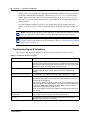
Troubleshooting an IP telephone . . . . . . . . . . . . . . . . . . . . . . . . . . . . . . . . . . . . . 38
If an IP telephone does not boot . . . . . . . . . . . . . . . . . . . . . . . . . . . . . . . . . . . 39
Telephone does not connect to system . . . . . . . . . . . . . . . . . . . . . . . . . . . . . 40
Slow connection . . . . . . . . . . . . . . . . . . . . . . . . . . . . . . . . . . . . . . . . . . . . . . . 40
One-way or no speech paths . . . . . . . . . . . . . . . . . . . . . . . . . . . . . . . . . . . . . 40
Dropped voice packets . . . . . . . . . . . . . . . . . . . . . . . . . . . . . . . . . . . . . . . . . . 40
Changing the contrast level . . . . . . . . . . . . . . . . . . . . . . . . . . . . . . . . . . . . . . 40
Configuring DHCP . . . . . . . . . . . . . . . . . . . . . . . . . . . . . . . . . . . . . . . . . . . . . . . . . 41
Modifying settings for Nortel IP telephones . . . . . . . . . . . . . . . . . . . . . . . . . . . . . . 42
Download firmware to a Nortel IP telephone . . . . . . . . . . . . . . . . . . . . . . . . . . . . . 44
Deregistering DNs for IP telephones . . . . . . . . . . . . . . . . . . . . . . . . . . . . . . . . . . . 45
Customizing feature labels . . . . . . . . . . . . . . . . . . . . . . . . . . . . . . . . . . . . . . . . . . 46
Moving IP telephones . . . . . . . . . . . . . . . . . . . . . . . . . . . . . . . . . . . . . . . . . . . . . . . . . 47
Keep DN alive . . . . . . . . . . . . . . . . . . . . . . . . . . . . . . . . . . . . . . . . . . . . . . . . . . . . 48
Configuring the Nortel Networks i2050 Software Phone . . . . . . . . . . . . . . . . . . . . . . . 49
Chapter 4
Installing NetVision telephones . . . . . . . . . . . . . . . . . . . . . . . . . . . . . . . . . . 51
NetVision connectivity . . . . . . . . . . . . . . . . . . . . . . . . . . . . . . . . . . . . . . . . . . . . . . . . . 51
Access points . . . . . . . . . . . . . . . . . . . . . . . . . . . . . . . . . . . . . . . . . . . . . . . . . . . . 51
Keycodes . . . . . . . . . . . . . . . . . . . . . . . . . . . . . . . . . . . . . . . . . . . . . . . . . . . . . . . 51
Handset and call functions . . . . . . . . . . . . . . . . . . . . . . . . . . . . . . . . . . . . . . . . . . 52
Configuring NetVision records . . . . . . . . . . . . . . . . . . . . . . . . . . . . . . . . . . . . . . . . . . . 52
Gathering system information before you start . . . . . . . . . . . . . . . . . . . . . . . . . . . 53
P0937663 03.1
Contents
5
Assigning H.323 Terminals records . . . . . . . . . . . . . . . . . . . . . . . . . . . . . . . . . . . . 53
Notes . . . . . . . . . . . . . . . . . . . . . . . . . . . . . . . . . . . . . . . . . . . . . . . . . . . . . . . 53
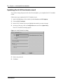
Adding a NetVision record in the Unified Manager . . . . . . . . . . . . . . . . . . . . . 54
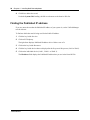
Testing the handset functions . . . . . . . . . . . . . . . . . . . . . . . . . . . . . . . . . . . . . . . . . . . 55
Updating the H.323 terminals record . . . . . . . . . . . . . . . . . . . . . . . . . . . . . . . . . . . . . . 56
Changing a handset Name . . . . . . . . . . . . . . . . . . . . . . . . . . . . . . . . . . . . . . . . . . . . . 57
Changing the DN record of a handset . . . . . . . . . . . . . . . . . . . . . . . . . . . . . . . . . . . . . 57
Deleting a NetVision telephone from the system . . . . . . . . . . . . . . . . . . . . . . . . . . . . . 57
Finding the Published IP address . . . . . . . . . . . . . . . . . . . . . . . . . . . . . . . . . . . . . . . . 58
Chapter 5
Configuring VoIP trunks . . . . . . . . . . . . . . . . . . . . . . . . . . . . . . . . . . . . . . . . 59
Installing keycodes . . . . . . . . . . . . . . . . . . . . . . . . . . . . . . . . . . . . . . . . . . . . . . . . . . . 59
Published IP address . . . . . . . . . . . . . . . . . . . . . . . . . . . . . . . . . . . . . . . . . . . . . . . . . . 59
Configuring media parameters . . . . . . . . . . . . . . . . . . . . . . . . . . . . . . . . . . . . . . . . . . 60
Configuring codecs . . . . . . . . . . . . . . . . . . . . . . . . . . . . . . . . . . . . . . . . . . . . . . . . 60
Setting silence compression . . . . . . . . . . . . . . . . . . . . . . . . . . . . . . . . . . . . . . . . . 61
Setting jitter buffers . . . . . . . . . . . . . . . . . . . . . . . . . . . . . . . . . . . . . . . . . . . . . . . . 62
Outgoing call configuration . . . . . . . . . . . . . . . . . . . . . . . . . . . . . . . . . . . . . . . . . . . . . 63
Putting VoIP lines into a line pool . . . . . . . . . . . . . . . . . . . . . . . . . . . . . . . . . . . . . 63
Configuring telephones to access the VoIP lines . . . . . . . . . . . . . . . . . . . . . . . . . 65
Configuring a remote gateway . . . . . . . . . . . . . . . . . . . . . . . . . . . . . . . . . . . . . . . 66
Configuring PSTN fallback . . . . . . . . . . . . . . . . . . . . . . . . . . . . . . . . . . . . . . . . . . 68
Enabling PSTN fallback . . . . . . . . . . . . . . . . . . . . . . . . . . . . . . . . . . . . . . . . . 69
Setting up the VoIP schedule . . . . . . . . . . . . . . . . . . . . . . . . . . . . . . . . . . . . . 69
Configuring routes . . . . . . . . . . . . . . . . . . . . . . . . . . . . . . . . . . . . . . . . . . . . . 70
Creating destination codes for fallback . . . . . . . . . . . . . . . . . . . . . . . . . . . . . . 72
Activating the VoIP schedule . . . . . . . . . . . . . . . . . . . . . . . . . . . . . . . . . . . . . 74
Turning on QoS monitor . . . . . . . . . . . . . . . . . . . . . . . . . . . . . . . . . . . . . . . . . 75
Incoming call configuration . . . . . . . . . . . . . . . . . . . . . . . . . . . . . . . . . . . . . . . . . . . . . 76
Assign a target line to the DN . . . . . . . . . . . . . . . . . . . . . . . . . . . . . . . . . . . . . . . . 76
Example configuration . . . . . . . . . . . . . . . . . . . . . . . . . . . . . . . . . . . . . . . . . . . . . . . . . 78
On Business Communications Manager Ottawa . . . . . . . . . . . . . . . . . . . . . . . . . 79
On Business Communications Manager Santa Clara . . . . . . . . . . . . . . . . . . . . . . 80
Making calls . . . . . . . . . . . . . . . . . . . . . . . . . . . . . . . . . . . . . . . . . . . . . . . . . . . . . 82
Connecting an i200X telephone . . . . . . . . . . . . . . . . . . . . . . . . . . . . . . . . . . . . . . 83
Connecting an i200X telephone on the LAN . . . . . . . . . . . . . . . . . . . . . . . . . 83
Remote access over VoIP trunks . . . . . . . . . . . . . . . . . . . . . . . . . . . . . . . . . . . . . . . . 84
Configuring NetMeeting clients . . . . . . . . . . . . . . . . . . . . . . . . . . . . . . . . . . . . . . . . . . 84
Quality of Service Monitor . . . . . . . . . . . . . . . . . . . . . . . . . . . . . . . . . . . . . . . . . . . . . . 86
Quality of Service Status . . . . . . . . . . . . . . . . . . . . . . . . . . . . . . . . . . . . . . . . . . . . 86
Updating the QoS monitor data . . . . . . . . . . . . . . . . . . . . . . . . . . . . . . . . . . . 86
IP Telephony Configuration Guide
6
Contents
Port settings . . . . . . . . . . . . . . . . . . . . . . . . . . . . . . . . . . . . . . . . . . . . . . . . . . . . . . . . . 86
Using firewalls . . . . . . . . . . . . . . . . . . . . . . . . . . . . . . . . . . . . . . . . . . . . . . . . . . . . 87
Port settings for legacy networks . . . . . . . . . . . . . . . . . . . . . . . . . . . . . . . . . . . . . 88
Using a gatekeeper . . . . . . . . . . . . . . . . . . . . . . . . . . . . . . . . . . . . . . . . . . . . . . . . . . . 88
The call signaling method . . . . . . . . . . . . . . . . . . . . . . . . . . . . . . . . . . . . . . . . . . . 89
Alias names . . . . . . . . . . . . . . . . . . . . . . . . . . . . . . . . . . . . . . . . . . . . . . . . . . 89
Modifying the call signaling method . . . . . . . . . . . . . . . . . . . . . . . . . . . . . . . . 90
Gatekeeper call scenarios . . . . . . . . . . . . . . . . . . . . . . . . . . . . . . . . . . . . . . . . . . . 91
Chapter 6
Typical applications . . . . . . . . . . . . . . . . . . . . . . . . . . . . . . . . . . . . . . . . . . . . 93
Networking with MCDN over VoIP trunks . . . . . . . . . . . . . . . . . . . . . . . . . . . . . . . . . . 93
Setting up MCDN over VoIP with fallback . . . . . . . . . . . . . . . . . . . . . . . . . . . . 94
MCDN functionality on fallback PRI lines . . . . . . . . . . . . . . . . . . . . . . . . . . . . 94
Networking multiple Business Communications Managers . . . . . . . . . . . . . . . . . 95
Setting up the system . . . . . . . . . . . . . . . . . . . . . . . . . . . . . . . . . . . . . . . . . . . 95
Multi-location chain with call center . . . . . . . . . . . . . . . . . . . . . . . . . . . . . . . . . . . . 96
Setting up the call chain configuration . . . . . . . . . . . . . . . . . . . . . . . . . . . . . . 97
Business Communications Manager to IP telephones . . . . . . . . . . . . . . . . . . . . . 97
Setting up a remote-based IP telephone . . . . . . . . . . . . . . . . . . . . . . . . . . . . 98
Appendix A
Efficient Networking . . . . . . . . . . . . . . . . . . . . . . . . . . . . . . . . . . . . . . . . . . . 99
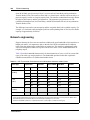
Determining the bandwidth requirements . . . . . . . . . . . . . . . . . . . . . . . . . . . . . . . . . . 99
Determining WAN link resources . . . . . . . . . . . . . . . . . . . . . . . . . . . . . . . . . . . . . 99
Link utilization . . . . . . . . . . . . . . . . . . . . . . . . . . . . . . . . . . . . . . . . . . . . . . . . . 99
Network engineering . . . . . . . . . . . . . . . . . . . . . . . . . . . . . . . . . . . . . . . . . . . . . . . . . 100
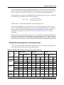
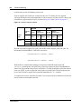
Bandwidth requirements on half duplex links . . . . . . . . . . . . . . . . . . . . . . . . . . . 101
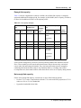
Bandwidth requirements on full duplex links . . . . . . . . . . . . . . . . . . . . . . . . . . . . 102
LAN engineering examples . . . . . . . . . . . . . . . . . . . . . . . . . . . . . . . . . . . . . . . . . 103
WAN engineering . . . . . . . . . . . . . . . . . . . . . . . . . . . . . . . . . . . . . . . . . . . . . . . . 104
Additional feature configuration . . . . . . . . . . . . . . . . . . . . . . . . . . . . . . . . . . . . . . . . . 105
Setting Non-linear processing . . . . . . . . . . . . . . . . . . . . . . . . . . . . . . . . . . . . . . . 105
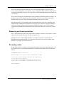
Determining network loading caused by IP telephony traffic . . . . . . . . . . . . . . . 105
Enough link capacity . . . . . . . . . . . . . . . . . . . . . . . . . . . . . . . . . . . . . . . . . . . 107
Not enough link capacity . . . . . . . . . . . . . . . . . . . . . . . . . . . . . . . . . . . . . . . 107
Other intranet resource considerations . . . . . . . . . . . . . . . . . . . . . . . . . . . . 108
Implementing the network, LAN engineering . . . . . . . . . . . . . . . . . . . . . . . . . . . 108
Further network analysis . . . . . . . . . . . . . . . . . . . . . . . . . . . . . . . . . . . . . . . . . . . . . . 108
Components of delay . . . . . . . . . . . . . . . . . . . . . . . . . . . . . . . . . . . . . . . . . . . . . 108
Reduce link delay . . . . . . . . . . . . . . . . . . . . . . . . . . . . . . . . . . . . . . . . . . . . . . . . 109
Reducing hop count . . . . . . . . . . . . . . . . . . . . . . . . . . . . . . . . . . . . . . . . . . . . . . 109
P0937663 03.1
Contents
7
Adjust the jitter buffer size . . . . . . . . . . . . . . . . . . . . . . . . . . . . . . . . . . . . . . 110
Reduce packet errors . . . . . . . . . . . . . . . . . . . . . . . . . . . . . . . . . . . . . . . . . . 110
Routing issues . . . . . . . . . . . . . . . . . . . . . . . . . . . . . . . . . . . . . . . . . . . . . . . . . . . 111
Post-installation network measurements . . . . . . . . . . . . . . . . . . . . . . . . . . . . . . . . . . 111
Appendix B
Silence compression . . . . . . . . . . . . . . . . . . . . . . . . . . . . . . . . . . . . . . . . . . 113
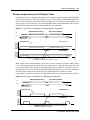
Silence compression on Half Duplex Links . . . . . . . . . . . . . . . . . . . . . . . . . . . . . . . . 113
Silence compression on Full Duplex Links . . . . . . . . . . . . . . . . . . . . . . . . . . . . . 115
Comfort noise . . . . . . . . . . . . . . . . . . . . . . . . . . . . . . . . . . . . . . . . . . . . . . . . . . . 116
Appendix C
Network performance utilities. . . . . . . . . . . . . . . . . . . . . . . . . . . . . . . . . . . 117
Ping . . . . . . . . . . . . . . . . . . . . . . . . . . . . . . . . . . . . . . . . . . . . . . . . . . . . . . . . . . . . . . 117
Traceroute . . . . . . . . . . . . . . . . . . . . . . . . . . . . . . . . . . . . . . . . . . . . . . . . . . . . . . . . . 117
Sniffer . . . . . . . . . . . . . . . . . . . . . . . . . . . . . . . . . . . . . . . . . . . . . . . . . . . . . . . . . . . . 117
Appendix D
Interoperability . . . . . . . . . . . . . . . . . . . . . . . . . . . . . . . . . . . . . . . . . . . . . . . 119
Speech path setup methods . . . . . . . . . . . . . . . . . . . . . . . . . . . . . . . . . . . . . . . . . . . 120
Media path redirection . . . . . . . . . . . . . . . . . . . . . . . . . . . . . . . . . . . . . . . . . . . . . . . . 120
Gatekeeper . . . . . . . . . . . . . . . . . . . . . . . . . . . . . . . . . . . . . . . . . . . . . . . . . . . . . . . . 120
Asymmetrical media channel negotiation . . . . . . . . . . . . . . . . . . . . . . . . . . . . . . . . . 121
No feedback busy station . . . . . . . . . . . . . . . . . . . . . . . . . . . . . . . . . . . . . . . 121
Symbol NetVision telephones . . . . . . . . . . . . . . . . . . . . . . . . . . . . . . . . . . . . . . . . . . 121
Appendix E
Quality of Service. . . . . . . . . . . . . . . . . . . . . . . . . . . . . . . . . . . . . . . . . . . . . 123
Setting QoS . . . . . . . . . . . . . . . . . . . . . . . . . . . . . . . . . . . . . . . . . . . . . . . . . . . . . . . . 123
Measuring Intranet QoS . . . . . . . . . . . . . . . . . . . . . . . . . . . . . . . . . . . . . . . . . . . . . . 124
Measuring end-to-end network delay . . . . . . . . . . . . . . . . . . . . . . . . . . . . . . 124
Measuring end-to-end packet loss . . . . . . . . . . . . . . . . . . . . . . . . . . . . . . . . . . . 125
Recording routes . . . . . . . . . . . . . . . . . . . . . . . . . . . . . . . . . . . . . . . . . . . . . . . . . 125
Adjusting Ping measurements . . . . . . . . . . . . . . . . . . . . . . . . . . . . . . . . . . . . . . 126
Adjustment for processing . . . . . . . . . . . . . . . . . . . . . . . . . . . . . . . . . . . . . . 126
Late packets . . . . . . . . . . . . . . . . . . . . . . . . . . . . . . . . . . . . . . . . . . . . . . . . . 127
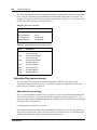
Measurement procedure . . . . . . . . . . . . . . . . . . . . . . . . . . . . . . . . . . . . . . . . . . . 127
Other measurement considerations . . . . . . . . . . . . . . . . . . . . . . . . . . . . . . . . . . 128
Decision: does the intranet meet IP telephony QoS needs? . . . . . . . . . . . . 128
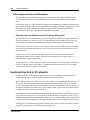
Implementing QoS in IP networks . . . . . . . . . . . . . . . . . . . . . . . . . . . . . . . . . . . . . . . 128
Traffic mix . . . . . . . . . . . . . . . . . . . . . . . . . . . . . . . . . . . . . . . . . . . . . . . . . . . . . . 129
TCP traffic behavior . . . . . . . . . . . . . . . . . . . . . . . . . . . . . . . . . . . . . . . . . . . . . . 129
Business Communications Manager router QoS support . . . . . . . . . . . . . . . . . . 130
IP Telephony Configuration Guide
8
Contents
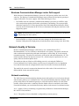
Network Quality of Service . . . . . . . . . . . . . . . . . . . . . . . . . . . . . . . . . . . . . . . . . . . . 130
Network monitoring . . . . . . . . . . . . . . . . . . . . . . . . . . . . . . . . . . . . . . . . . . . . . . . 130
Quality of Service parameters . . . . . . . . . . . . . . . . . . . . . . . . . . . . . . . . . . . . . . . 131
Packet loss . . . . . . . . . . . . . . . . . . . . . . . . . . . . . . . . . . . . . . . . . . . . . . . . . . 131
Packet delay . . . . . . . . . . . . . . . . . . . . . . . . . . . . . . . . . . . . . . . . . . . . . . . . . 131
Delay variation (jitter) . . . . . . . . . . . . . . . . . . . . . . . . . . . . . . . . . . . . . . . . . . 131
Fallback to PSTN . . . . . . . . . . . . . . . . . . . . . . . . . . . . . . . . . . . . . . . . . . . . . . . . 132
Glossary . . . . . . . . . . . . . . . . . . . . . . . . . . . . . . . . . . . . . . . . . . . . . . . . . . . . 133
Index . . . . . . . . . . . . . . . . . . . . . . . . . . . . . . . . . . . . . . . . . . . . . . . . . . . . . . . 137
P0937663 03.1
9
Figures
Figure 1
Network diagram . . . . . . . . . . . . . . . . . . . . . . . . . . . . . . . . . . . . . . . . . . . 19
Figure 2
Global IP settings . . . . . . . . . . . . . . . . . . . . . . . . . . . . . . . . . . . . . . . . . . . 28
Figure 3
Setting the Published IP address . . . . . . . . . . . . . . . . . . . . . . . . . . . . . . . 29
Figure 4
Set registration properties . . . . . . . . . . . . . . . . . . . . . . . . . . . . . . . . . . . . 33
Figure 5
IP Terminal status . . . . . . . . . . . . . . . . . . . . . . . . . . . . . . . . . . . . . . . . . . . 42
Figure 6
Configuration menu . . . . . . . . . . . . . . . . . . . . . . . . . . . . . . . . . . . . . . . . . 42
Figure 7
IP Terminal status dialog . . . . . . . . . . . . . . . . . . . . . . . . . . . . . . . . . . . . . 43
Figure 8
Configuration menu . . . . . . . . . . . . . . . . . . . . . . . . . . . . . . . . . . . . . . . . . 44
Figure 9
Deregister DN from Configuration menu . . . . . . . . . . . . . . . . . . . . . . . . . 45
Figure 10
Label set 1-6, voicemail defaults . . . . . . . . . . . . . . . . . . . . . . . . . . . . . . . 46
Figure 11
i2050 Communications server . . . . . . . . . . . . . . . . . . . . . . . . . . . . . . . . . 49
Figure 12
i2050 Switch type . . . . . . . . . . . . . . . . . . . . . . . . . . . . . . . . . . . . . . . . . . . 49
Figure 13
H.323 Terminal list dialog . . . . . . . . . . . . . . . . . . . . . . . . . . . . . . . . . . . . . 54
Figure 14
H.323 Terminal List dialog . . . . . . . . . . . . . . . . . . . . . . . . . . . . . . . . . . . . 56
Figure 15
Media parameters . . . . . . . . . . . . . . . . . . . . . . . . . . . . . . . . . . . . . . . . . . 60
Figure 16
Media Parameters . . . . . . . . . . . . . . . . . . . . . . . . . . . . . . . . . . . . . . . . . . 61
Figure 17
Media parameters . . . . . . . . . . . . . . . . . . . . . . . . . . . . . . . . . . . . . . . . . . 62
Figure 18
Trunk/Line data . . . . . . . . . . . . . . . . . . . . . . . . . . . . . . . . . . . . . . . . . . . . 64
Figure 19
Line pool access code setting . . . . . . . . . . . . . . . . . . . . . . . . . . . . . . . . . 65
Figure 20
Remote gateway list . . . . . . . . . . . . . . . . . . . . . . . . . . . . . . . . . . . . . . . . . 66
Figure 21
Remote gateway dialog . . . . . . . . . . . . . . . . . . . . . . . . . . . . . . . . . . . . . . 67
Figure 22
PSTN fallback diagram . . . . . . . . . . . . . . . . . . . . . . . . . . . . . . . . . . . . . . 68
Figure 23
VoIP Routing Service . . . . . . . . . . . . . . . . . . . . . . . . . . . . . . . . . . . . . . . . 69
Figure 24
Add route dialog . . . . . . . . . . . . . . . . . . . . . . . . . . . . . . . . . . . . . . . . . . . . 70
Figure 25
Add destination code dialog . . . . . . . . . . . . . . . . . . . . . . . . . . . . . . . . . . . 72
Figure 26
VoIP schedule . . . . . . . . . . . . . . . . . . . . . . . . . . . . . . . . . . . . . . . . . . . . . 73
Figure 27
Remote Gateway list . . . . . . . . . . . . . . . . . . . . . . . . . . . . . . . . . . . . . . . . 75
Figure 28
Remote Gateway dialog . . . . . . . . . . . . . . . . . . . . . . . . . . . . . . . . . . . . . . 75
Figure 29
Example PSTN fallback . . . . . . . . . . . . . . . . . . . . . . . . . . . . . . . . . . . . . . 78
Figure 30
NetMeeting options . . . . . . . . . . . . . . . . . . . . . . . . . . . . . . . . . . . . . . . . . 84
Figure 31
NetMeeting advanced options . . . . . . . . . . . . . . . . . . . . . . . . . . . . . . . . . 85
Figure 32
Port Ranges . . . . . . . . . . . . . . . . . . . . . . . . . . . . . . . . . . . . . . . . . . . . . . . 87
Figure 33
Port ranges dialog box . . . . . . . . . . . . . . . . . . . . . . . . . . . . . . . . . . . . . . . 87
Figure 34
Local gateway IP interface . . . . . . . . . . . . . . . . . . . . . . . . . . . . . . . . . . . . 90
Figure 35
Business Communications Manager systems with a gatekeeper . . . . . . 91
Figure 36
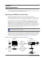
M1 to Business Communications Manager network diagram . . . . . . . . . 93
Figure 37
Multiple Business Communications Manager systems network diagram 95
Figure 38
M1 to Business Communications Manager network diagram . . . . . . . . . 96
Figure 39
Connecting to IP telephones . . . . . . . . . . . . . . . . . . . . . . . . . . . . . . . . . . 97
Figure 40
LAN engineering peak transmission . . . . . . . . . . . . . . . . . . . . . . . . . . . 103
IP Telephony Configuration Guide
10
Figures
Figure 41
Peak traffic, WAN link . . . . . . . . . . . . . . . . . . . . . . . . . . . . . . . . . . . . . . . 104
Figure 42
Calculating network load with IP telephony traffic . . . . . . . . . . . . . . . . . 105
Figure 43
Network loading bandwidth . . . . . . . . . . . . . . . . . . . . . . . . . . . . . . . . . . 106
Figure 44
One Call on a Half Duplex Link Without Silence compression . . . . . . . . 113
Figure 45
One Call on a Half Duplex Link With Silence compression . . . . . . . . . . 114
Figure 46
Two Calls on a Half Duplex Link With Silence compression . . . . . . . . . 114
Figure 47
One Call on a Full Duplex Link Without Silence compression . . . . . . . . 115
Figure 48
One Call on a Full Duplex Link With Silence compression . . . . . . . . . . 115
Figure 49
Two Calls on a Full Duplex Link With Silence compression . . . . . . . . . . 116
Figure 50
Relationship between users and services . . . . . . . . . . . . . . . . . . . . . . . 123
P0937663 03.1
11
Tables
Table 1
Network diagram prerequisites . . . . . . . . . . . . . . . . . . . . . . . . . . . . . . . . 25
Table 2
Network device checklist . . . . . . . . . . . . . . . . . . . . . . . . . . . . . . . . . . . . . 25
Table 3
Network assessment . . . . . . . . . . . . . . . . . . . . . . . . . . . . . . . . . . . . . . . . 26
Table 4
Resource assessment . . . . . . . . . . . . . . . . . . . . . . . . . . . . . . . . . . . . . . . 27
Table 5
Keycodes . . . . . . . . . . . . . . . . . . . . . . . . . . . . . . . . . . . . . . . . . . . . . . . . . 27
Table 6
Business Communications Manager system configuration . . . . . . . . . . . 28
Table 7
IP telephone provisioning . . . . . . . . . . . . . . . . . . . . . . . . . . . . . . . . . . . . . 30
Table 8
IP telephone server configurations . . . . . . . . . . . . . . . . . . . . . . . . . . . . . . 37
Table 9
IP telephony display messages . . . . . . . . . . . . . . . . . . . . . . . . . . . . . . . . 38
Table 10
Relabelling examples . . . . . . . . . . . . . . . . . . . . . . . . . . . . . . . . . . . . . . . . 47
Table 11
QoS status
Table 12
VoIP Transmission Characteristics for unidirectional continuous media stream 100
. . . . . . . . . . . . . . . . . . . . . . . . . . . . . . . . . . . . . . . . . . . . . . . 86
Table 13
Bandwidth Requirements per Gateway port for half-duplex links . . . . . 101
Table 14
Bandwidth Requirements per Gateway port for Full-duplex links . . . . . 102
Table 15
Link capacity example . . . . . . . . . . . . . . . . . . . . . . . . . . . . . . . . . . . . . . 107
Table 16
Business Communications Manager 2.5 Product Interoperability Summary 119
Table 17
Engineering specifications . . . . . . . . . . . . . . . . . . . . . . . . . . . . . . . . . . . 119
Table 18
Supported voice payload sizes . . . . . . . . . . . . . . . . . . . . . . . . . . . . . . . 120
Table 19
Name comparison . . . . . . . . . . . . . . . . . . . . . . . . . . . . . . . . . . . . . . . . . 121
Table 20
Quality of voice service . . . . . . . . . . . . . . . . . . . . . . . . . . . . . . . . . . . . . 124
Table 21
Site pairs and routes . . . . . . . . . . . . . . . . . . . . . . . . . . . . . . . . . . . . . . . 126
Table 22
Computed load of voice traffic per link . . . . . . . . . . . . . . . . . . . . . . . . . . 126
Table 23
Delay and error statistics . . . . . . . . . . . . . . . . . . . . . . . . . . . . . . . . . . . . 127
IP Telephony Configuration Guide
12
Tables
P0937663 03.1
13
Preface
This guide describes IP Telephony functionality for the Business Communications Manager 2.5
and 2.5 plus Feature Pack 1 systems. This includes information on Nortel IP terminals such as the
i2002, i2004 telephone and the Nortel Networks i2050 Software Phone, the Symbol NetVision and
NetVision data telephones (H.323-protocol devices), and VoIP trunks and H.323 trunking with
such applications as NetMeeting.
Before you begin
This guide is intended for installers and managers of a Business Communications Manager 2.5
system. Prior knowledge of IP networks is required.
Before using this guide, the Business Communications Manager 2.5 system must be configured
and tested.
This guide assumes:
•
•
•
•
•
You have planned the telephony and data requirements for your Business Communications
Manager 2.5 system.
The Business Communications Manager 2.5 is installed and initialized, and the hardware is
working. External lines and internal telephones and telephony equipment are connected to the
appropriate media bay modules on the Business Communications Manager 2.5.
Configuration of lines is complete.
Operators have a working knowledge of the Windows operating system and of graphical user
interfaces.
Operators who manage the data portion of the system are familiar with network management
and applications.
Refer to Chapter 2, “Prerequisites checklist,” on page 25 for more information.
Symbols used in this guide
This guide uses these symbols to draw your attention to important information:
Caution: Caution Symbol
Alerts you to conditions where you can damage the equipment.
Danger: Electrical Shock Hazard Symbol
Alerts you to conditions where you can get an electrical shock.
Warning: Warning Symbol
Alerts you to conditions where you can cause the system to fail or work improperly.
IP Telephony Configuration Guide
14
Preface
Note: Note/Tip symbol
Alerts you to important information.
Tip: Note/Tip symbol
Alerts you to additional information that can help you perform a task.
Text conventions
This guide uses these following text conventions:
angle brackets (< >)
Represent the text you enter based on the description inside the
brackets. Do not type the brackets when entering the command.
Example: If the command syntax is
ping <ip_address>, you enter
ping 192.32.10.12
bold Courier text
Represent command names, options and text that you need to enter.
Example: Use the dinfo command.
Example: Enter show ip {alerts|routes}.
italic text
Represents terms, book titles and variables in command syntax
descriptions. If a variable is two or more words, the words are
connected by an underscore.
Example: The command syntax
show at <valid_route>,
valid_route is one variable and you substitute one value for it.
plain Courier
text
Represents command syntax and system output, such as prompts and
system messages.
Example: Set Trap Monitor Filters
Acronyms
This guide uses the following acronyms:
ATM
Asynchronous Transfer Mode
BCM
Business Communications Manager
CIR
Committed Information Rate
DID
Direct Inward Dialing
DOD
Direct Outward Dialing
DIBTS
Digital In-Band Trunk Signalling
DSB
DIBTS Signalling Buffer
P0937663 03.1
Preface
IEEE802 ESS
Institute of Electrical and Electronics Engineers, Inc., standard 802
Electronic Switching System Identification code
ITU
International Telecommunication Union
IXC
IntereXchange Carrier
IP
Internet Protocol
ISDN
Integrated Services Digital Network
LAN
Local Area Network
LATA
Local Access and Transport Area
LEC
Local Exchange Carrier
MOS
Mean Opinion Score
NVPA
NetVision Phone Administrator
PCM
Pulse Code Modulation
PiPP
Power inline patch panel
PPP
Point-to-Point Protocol
PRI
Primary Rate Interface
PSTN
Public Switched Telephone Network
QoS
Quality of Service
RAS
Registration, Admissions and Status
RTP
Real-time Transfer Protocol
SNMP
Simple Network Management Protocol
TCP
Transmission Control Protocol
UDP
User Datagram Protocol
UTPS
UNISTIM Terminal Proxy Server
VoIP
Voice over Internet Protocol
WAN
Wide Area Network
15
Related publications
Documents referenced in the Business Communications Manager 2.5 IP Telephony Configuration
Guide, include:
•
•
•
•
Installation and Maintenance Guide
Software Keycode Installation Guide
Programming Operations Guide
Telephone Feature Programming Guide
IP Telephony Configuration Guide
16
Preface
How to get help
•
USA and Canada
Authorized Distributors - ITAS Technical Support
Telephone: 1-800-4NORTEL (1-800-466-7835)
If you already have a PIN Code, you can enter Express Routing Code (ERC) 196#
If you do not yet have a PIN Code, or for general questions and first line support, enter ERC
338#
Website: http://www.nortelnetworks.com/itas/
email: [email protected]
Presales Support (CSAN)
Telephone: 1-800-4NORTEL (1-800-466-7835)
Use Express Routing Code (ERC) 1063#
•
EMEA (Europe, Middle East, Africa)
Technical Support - CTAS
Telephone: 00800 800 89009 or 33 4 9296 1341
Fax: 33 49296 1598
email: [email protected]
•
CALA (Caribbean & Latin America)
Technical Support - CTAS
Telephone: 1-954-858-7777
email: [email protected]
•
APAC (Asia Pacific)
Technical Support - CTAS
Telephone: +61 388664627
Fax: +61 388664644
email: [email protected]
P0937663 03.1
17
Chapter 1
Introduction
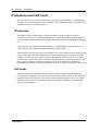
IP Telephony provides the flexibility, affordability, and expandability of the Internet to the world
of voice communications.
Business Communications Manager 2.5 with voice over IP (VoIP) provides several critical
advantages:
•
•
•
•
•
•
Cost Savings. IP networks can be significantly less expensive to operate and maintain than
traditional networks. The simplified network infrastructure of an Internet Telephony solution
cuts costs by connecting IP telephones over your LAN and eliminates the need for dual
cabling. Internet Telephony can also eliminate toll charges on site-to-site calls via global
four-digit dialing. And, by using the extra bandwidth on your WAN for IP Telephony, you
leverage the untapped capabilities of your data infrastructure to maximize the return on your
current network investment.
Portability and flexibility. Employees can be more productive because they are no longer
confined by geographic location. IP telephones work anywhere on the network, even over a
remote connection. With Nortel Networks wireless e-mobility solutions, your phone, laptop,
or scanner can work anywhere on the network where a Nortel Networks Access Point is
installed. Network deployments and reconfigurations are simplified, and service can be
extended to remote sites and home offices over cost-effective IP links.
Simplicity and consistency. A common approach to service deployment allows further
cost-savings from the use of common management tools, resource directories, flow-through
provisioning, and a consistent approach to network security. As well, customers can centrally
manage a host of multimedia services and business-building applications from a central point
via a Web-based browser. The ability to network existing PBXs using IP can bring new
benefits to your business. For example, the ability to consolidate voice mail onto a single
system, or to fewer systems, making it easier for voice mail users to network.
Compatibility. Internet Telephony is supported over a wide variety of transport technologies.
A user can gain access to just about any business system through an analog line, Digital
Subscriber Line, a LAN, frame relay, asynchronous transfer mode, SONET or wireless
connection.
Scalability. A future-proof, flexible, and safe solution, combined with high reliability, allows
your company to focus on customer needs, not network problems. Nortel Networks Internet
Telephony solutions offer hybrid environments that leverage existing investments in Meridian
and Norstar systems.
Increased customer satisfaction. Breakthrough e-business applications help deliver the
top-flight customer service that leads to success. By providing your customers with rapid
access to sales and support personnel via telephone, the Web, and e-mail, your business can
provide better customer service than ever before.
IP Telephony Configuration Guide
18
Chapter 1
Introduction
IP telephones and VoIP trunks
This guide describes two similar applications for IP telephony on the Business Communications
Manager 2.5 system: IP telephones and VoIP trunks. These applications can be used separately or
together as a network voice/data solution.
IP telephones
IP telephones offer the functionality of regular telephones, but do not require a hardwire
connection to the Business Communications Manager. Instead, they must be plugged into an IP
network which is connected to the LAN or WAN card on the Business Communications Manager
2.5.
Calls made from IP telephones through the Business Communications Manager can pass over
VoIP trunks or across a Public Switched Telephone Network (PSTN).
Nortel Networks provides two types of IP telephones. The i-series telephones are hardwired to the
system, in the case of the i2002 and the i2004, or are accessed through your desktop or lap top
computer, as in the case of the Nortel Networks i2050 Software Phone. Emobility voice can be
provided using Symbol* NetVision* or NetVision Data telephones, connecting through an access
point wired to an internet connection configured to the LAN or a WAN on your Business
Communications Manager. NetVision telephones use the H.323 protocol to connect to the system.
VoIP trunks
VoIP trunks allow voice signals to travel across IP networks. A gateway within the Business
Communications Manager 2.5 converts the voice signal into IP packets, which are then transmitted
through the IP network. The device at the other end reassembles the packets into a voice signal.
NetMeeting is one of the H.323 protocol trunk devices that the 2.5 Business Communications
Manager system supports.
P0937663 03.1
Chapter 1
Introduction
19
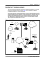
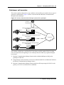
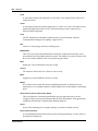
Creating the IP telephony network
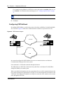
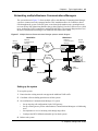
This section explains the components of the Business Communications Manager 2.5 system and
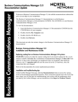
the devices it interoperates to create a network. Figure 1 shows components of a Business
Communications Manager 2.5 network configuration.
Note that the two Business Communications Manager systems are connected both through a PSTN
connection and through a WAN connection. The WAN connection uses VoIP trunks. If the PSTN
connections use dedicated ISDN lines, the two systems have backup private networks to each
other. Both Business Communications Manager systems use VoIP trunks through a common
WAN to connect to the Meridian (M1-ITG) system.
Figure 1 Network diagram
Business Communications
Manager A
Router
LAN A
PSTN
Internet
IP telephone A
Digital telephone A
Access Point
I2050 telephone A
SND
MENU
FCT
RCL
NAME
1
2
ABC
5
JKL
END
3
GHI
6
MNO
7
PQRS
8
TUV
9
WXYZ
<
0
OPR
#
>
CLR
STO
Router
DEF
4
HOLD
NetVision
telephone
(H 323 device A)
WAN
LAN B
Gatekeeper
Business Communications
Manager B
Inspe
ct FOR
WAR
D Calle
rs
MXP
M1-ITG
H 323 Device B
IP telephone B
Meridian set A
IP Telephony Configuration Guide
20
Chapter 1
Introduction
Business Communications Manager 2.5
The Business Communications Manager 2.5 is a key building block in creating your network. It
interoperates with many devices, including the Meridian 1 system and H.323 devices. In the
diagram shown in Figure 1 on page 19, the Business Communications Manager 2.5 system is
connected to devices through multiple IP networks, as well as through the PSTN. Multiple
Business Communications Manager 2.5 systems also can be linked together on a network of VoIP
trunks and/or dedicated physical lines. Refer to Chapter 6, “Typical applications,” on page 93.
In the figure on the previous page, note that Business Communications Manager A is connected to
a LAN through a LAN card, to a WAN through a WAN card, and to a PSTN through trunk media
bay modules. Through these networks, the system accesses other systems and network equipment
connected to the network.
M1-ITG
The Meridian 1 Internet Telephony Gateway (M1-ITG) allows Meridian 1 systems to
communicate with H.323-based devices, such as the Business Communications Manager 2.5. In
Figure 1 on page 19, telephones on the M1, such as Meridian telephone A, can initiate and receive
calls with the other telephones on the system across IP networks.
To provide fallback at times when IP traffic cannot pass, you can also connect the Meridian to the
Business Communications Managers through ISDN PRI SL-1 lines, which provide the same
MCDN capability that you can achieve through the VoIP trunks with MCDN active.
Refer to the Business Communications Manager Programming Operations Guide for a description
of MCDN features and networking with PRI SL-1 lines. “Networking with MCDN over VoIP
trunks” on page 93 describes how to provide the same network over VoIP lines.
A Business Communications Manager connected to an M1-ITG using the MCDN protocol can
provide access to a central voice mail and call attendant system, which can streamline multi-office
telephony administration.
Telephones
The Business Communications Manager 2.5 system can communicate using digital telephones
(T7100, M7100, M7100N, T7208, M7208, M7208N, T7316, M7310, M7310N, M7324, and
M7324N), cordless telephones (Companion, DECT, T7406), IP telephones and applications
(i2002, i2004, Nortel Networks i2050 Software Phone), and IP/wireless telephones (NetVision
and NetVision Data telephones). With this much flexibility, the Business Communications
Manager can provide the type of service you require to be most productive in your business.
P0937663 03.1
Chapter 1
Introduction
21
VoIP trunks and analog/digital telephones
While analog and digital telephones cannot be connected to the Business Communications
Manager 2.5 system with an IP connection, they can make and receive calls to and from other
systems through VoIP trunks. Calls from IP telephones to system telephones are received through
the LAN or WAN card and are translated within the Business Communications Manager to voice
channels.
VoIP trunks and IP telephones
The IP telephones connect to the Business Communications Manager across an IP network
through either on a LAN or a WAN. From the Business Communications Manager connection,
they can then use standard lines or VoIP trunks to communicate to other telephones on other public
or private networks.
Gatekeeper
A gatekeeper tracks IP addresses of specified devices, and provides authorization for making and
accepting calls for these devices. A gatekeeper is not required for the Business Communications
Manager 2.5 system, but can be useful on networks with a large number of devices. Referring,
again, to Figure 1 on page 19, for example: Digital telephone A wants to call IP telephone B,
through Business Communications Manager B, which is under the control of the gatekeeper.
Digital telephone A sends a request to the gatekeeper. The gatekeeper, depending on how it is
programmed, provides Digital telephone A with the information it needs to contact IP telephone B.
IP network
In the network shown in Figure 1 on page 19, several LANs and a WAN are shown. When
planning your network, be sure to consider all requirements for a data network. Your network
administrator should be able to advise you about the network setup and how the Business
Communications Manager fits into the network.
WAN
A Wide Area Network (WAN) is a communications network that covers a wide geographic area,
such as state or country. For Business Communications Manager 2.5, a WAN is any IP network
connected to a WAN card on the Business Communications Manager 2.5 system. This may also be
a direct connection to another Business Communications Manager 2.5 system.
If you want to deploy IP telephones or NetVision telephones that will be connected to a LAN
outside of the LAN that the Business Communications Manager is installed on, you must ensure
the Business Communications Manager has a WAN connection. This includes ensuring that you
obtain IP addresses and routing information that allows the remote telephones to find the Business
Communications Manager, and vice versa.
IP Telephony Configuration Guide
22
Chapter 1
Introduction
The Business Communications Manager 2.5 Programming Operations Guide has a data section
that describes the internet protocols and data settings that the Business Communications Manager
requires or is compatible with. Ensure that this connection is correctly set up and working before
you attempt to deploy any remote IP devices.
LAN
A Local Area Network (LAN) is a communications network that serves users within a confined
geographical area. For Business Communications Manager 2.5, a LAN is any IP network
connected to a LAN card on the Business Communications Manager 2.5 system. Often, the LAN
can include a router that forms a connection to the Internet. A Business Communications Manager
can have up to two LAN connections.
Public Switched Telephone Network
The Public Switched Telephone Network (PSTN) can play an important role in IP telephony
communications. In many installations, the PSTN forms a fallback route. If a call across a VoIP
trunk does not have adequate voice quality, the call can be routed across the PSTN instead, either
on public lines or on a dedicated ISDN connection between the two systems. The Business
Communications Manager also serves as a gateway to the PSTN for all voice traffic on the system.
Key IP telephony concepts
In traditional telephony, the voice path between two telephones is circuit switched. This means
that the analog or digital connection between the two telephones is dedicated to the call. The voice
quality is usually excellent, since there is no other signal to interfere.
In IP telephony, voice quality between IP telephones can vary significantly from call to call and
time of day. When two IP telephones are on a call, each IP telephone encodes the speech at the
handset microphone into small data packets called frames. The system sends the frames across the
IP network to the other telephone, where the frames are decoded and played at the handset
receiver. If some of the frames get lost while in transit, or are delayed too long, the receiving
telephone experiences poor voice quality.
Codecs
The algorithm used to compress and decompress voice is embedded in a software entity called a
codec (COde-DECode).
Two popular Codecs are G.711 and G.729. The G.711 Codec samples voice at 64 kilobits per
second (kbps) while G.729 samples at a far lower rate of 8 kbps.
Voice quality is better when using a G.711 CODEC, but more network bandwidth is used to
exchange the voice frames between the telephones.
P0937663 03.1
Chapter 1
Introduction
23
If you experience poor voice quality, and suspect it is due to heavy network traffic, you can get
better voice quality by configuring the IP telephone to use a G.729 CODEC.
Jitter Buffer
Voice frames are transmitted at a fixed rate, because the time interval between frames is constant.
If the frames arrive at the other end at the same rate, voice quality is perceived as good. In many
cases, however, some frames can arrive slightly faster or slower than the other frames. This is
called jitter, and degrades the perceived voice quality. To minimize this problem, configure the IP
telephone with a jitter buffer for arriving frames.
This is how the jitter buffer works:
Assume a jitter buffer setting of five frames.
•
•
•
The IP telephone firmware places the first five arriving frames in the jitter buffer.
When frame six arrives, the IP telephone firmware places it in the buffer, and sends frame one
to the handset speaker.
When frame seven arrives, the IP telephone buffers it, and sends frame two to the handset
speaker.
The net effect of using a jitter buffer is that the arriving packets are delayed slightly in order to
ensure a constant rate of arriving frames at the handset speaker.
This delaying of packets can provide somewhat of a communications challenge, as speech is
delayed by the number of frames in the buffer. For one-sided conversations, there are no issues.
However, for two-sided conversations, where one party tries to interrupt the other speaking party,
it can be annoying. In this second situation, by the time the voice of the interrupter reaches the
interruptee, the interruptee has spoken (2*jitter size) frames past the intended point of interruption.
In cases where very large jitter sizes are used, some users revert to saying OVER when they wish
the other party to speak.
Possible jitter buffer settings, and corresponding voice packet latency (delay) for the Business
Communications Manager 2.5 system IP telephones are:
•
•
•
•
None
Small (.06 seconds)
Medium (.12 seconds)
Large (.18 seconds)
QoS routing
When it sends a voice frame onto the network, the IP telephone firmware places some header
information on the frame.
IP Telephony Configuration Guide
24
Chapter 1
Introduction
The header contains the network address of the sending and receiving IP telephones, and a TOS
(Type Of Service) byte, which contains a routing priority.
The IP telephone firmware establishes the TOS byte to the highest possible priority. This means
that, as the voice frame travels through the network, the routers it encounters give it higher routing
priority than competing data frames of information that do not require real-time processing, such
as file transfers, WEB downloads, e-mails, etc. This process of prioritizing data frames is Quality
of Service (QoS) routing.
The Business Communications Manager 2.5 system does QOS routing, but if one or more routers
along the network route do not support QOS routing, this can impact voice quality. Business
Communications Manager 2.5 system QoS can also be configured so that the system reverts to a
circuit-switched line if a suitable QoS cannot be guaranteed.
P0937663 03.1
25
Chapter 2
Prerequisites checklist
Before you set up VoIP trunks or IP telephones on a Business Communications Manager,
complete the following checklists to ensure that the system is correctly set up. Some questions do
not apply to all installations.
Network diagram
To aid in installation, a Network Diagram is needed to provide a basic understanding of how the
network is configured. Before you install IP functionality, you must have a network diagram that
captures all of the information described in Table 1. If you are configuring IP telephones but not
voice over IP (VoIP) trunks, you do not need to answer 1.d and 1.e.
Table 1 Network diagram prerequisites
Prerequisites
Yes
1.a Has a network diagram been developed?
1.b Does the network diagram contain any routers, switches or bridges with corresponding
IP addresses and bandwidth values for WAN or LAN links?
1.c Does the network diagram contain IP Addresses, netmasks, and network locations of all Business
Communications Managers?
1.d Answer this if your system will use IP trunks, otherwise, leave it blank: Does the network diagram
contain IP Addresses and netmasks of any other VoIP gateways that you need to connect to?
1.e Answer this only if your system will use a gatekeeper, otherwise, leave it blank: Does the network
diagram contain the IP address for any Gatekeeper that may be used?
Network devices
Table 2 contains questions about devices on the network such as firewalls, NAT devices, and
DHCP servers.
•
•
Table 2
If the network uses public IP addresses, complete 2.b.
If the network uses private IP addresses, complete 2.c to 2.d.
Network device checklist
Prerequisites
Yes
No
2.a Is the network using private IP addresses?
2.b Are there enough public IP addresses to accommodate all IP telephones and the Business
Communications Manager?
IP Telephony Configuration Guide
26
Chapter 2
Prerequisites checklist
Prerequisites
Yes
No
2.c Does the system have a firewall/NAT device, or will the Business Communications
Manager be used as a firewall/NAT device?
NOTE: NetVision handsets do not work on a network that has NAT between the handset
and the system..
2.d If the Business Communications Manager is to be used as a firewall/NAT device, do the
firewall rules fit within the 32 input rules and 32 output rules that the Business
Communications Manager provides?
2.e A hub-based core will not have suitable performance for IP Telephony. Does the network
use a non-hub solution at its core?
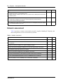
Network assessment
Table 3 questions are meant to ensure that the network is capable of handling IP Telephony, and
that existing network services are not adversely affected.
Table 3 Network assessment
Prerequisites
3.a Has a network assessment been completed?
3.b Has the number of switch/hub ports available and used in the LAN infrastructure been
calculated?
3.c Does the switch use VLANs? If so, get the VLAN port number.
3.d Have the used and available IP addresses for each LAN segment been calculated?
3.e Has DHCP usage and location been recorded?
3.f Has the speed and configuration of the LAN been calculated?
3.g Has the estimated latency values between network locations been calculated?
3.h Have the Bandwidth/CIR utilization values for all WAN links been calculated?
3.i Has the quality of service availability on the network been calculated?
P0937663 03.1
Yes
No
Chapter 2
Prerequisites checklist
27
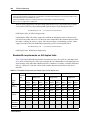
Resource assessment
Answer the questions in Table 4 to determine if you have allocated sufficient resources on the
Business Communications Manager for IP telephony.
For information about changing the DS30 channel split for the Business Communications
Manager and allocating media resources, refer to the Business Communications Manager
Installation and Maintenance Guide (DS30 split) and the Programming Operations Guide (data
sections).
Table 4 Resource assessment
Prerequisites
Yes
No
4.a Has a Business Communications Manager Resource Assessment been performed using
the resource questionnaire in the Programming Operations Guide?
4.b Has an analysis been done to determine which DS-30 split is appropriate for the system?
Has the DS-30 split been changed to 3/5, if necessary?
4.c Have all necessary media resources for IP trunks, clients, vmail or WAN dialup been
assigned or dedicated?
Keycodes
All elements of VoIP trunks and IP telephony are locked by the Business Communications
Manager keycode system. You can purchase keycodes for the amount of access you want for your
system. Additional keycodes can be added later, providing there are adequate resources to handle
them.
Table 5 Keycodes
Prerequisites
Yes
No
5.a Complete this question only if you are using VoIP trunks: Do you have enough VoIP
keycodes?
5.b Complete this question only if you are using IP telephones: Do you have enough IP
client keycodes?
IP Telephony Configuration Guide
28
Chapter 2
Prerequisites checklist
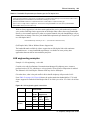
Business Communications Manager system configuration
Several sections of the Business Communications Manager must be properly configured prior to
activation of IP telephony.
Answer the questions in Table 6 to determine if your Business Communications Manager has been
correctly configured.
Table 6 Business Communications Manager system configuration
Prerequisites
Yes
No
6.a Is the LAN functioning correctly with the Business Communications Manager?
6.b Is the WAN functioning correctly with the Business Communications Manager?
6.c Have you determined the published IP address for the system? Refer to “Defining
published IP address” on page 28.
6.d Has a dialing plan been created, taking into account special considerations for
IP telephony and private and public networking?
6.e Do you want the system to auto-assign DNs? If no, complete 6.f.
6.f Have DN records been programmed for the corresponding IP clients?
Defining published IP address
The published IP address is the IP address used by computers on the public network to find the
Business Communications Manager. For example, if a Business Communications Manager has a
LAN interface (LAN1) that is connected only to local office IP terminals and a WAN interface
(WAN1) that is connected to the public network, then WAN1 should be set to the published IP
address.
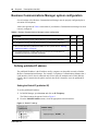
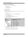
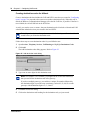
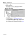
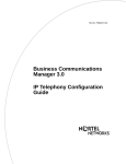
Setting the Global IP (published IP)
To set the published IP address:
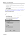
1
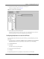
In Unified Manager, open Services and click on IP Telephony.
The Global settings tab appears. Refer to Figure 2.
2
From the Published Address menu, select the appropriate network interface.
Figure 2 Global IP settings
P0937663 03.1
Chapter 2
Prerequisites checklist
29
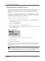
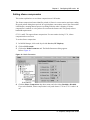
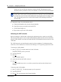
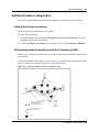
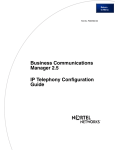
Determining the published IP address
Use the flowchart in Figure 3 to determine which card should be set as the published IP address.
Figure 3 Setting the Published IP address
Start
Set the network interface with
Is NAT enabled?
N
the most anticipated VoIP traffic
as the Published IP address
Y
Set the network interface on the
Is the Business Communications
N
Manager expected to connect to
private side as the published
IP address
devices on the public side?
Y
Are all of your public side
Set the network interface on the
N
public side as the published
IP address
devices using a VPN?
Y
D o you anticipate the m ost VoIP
Public
traffic on your public or private side?
Set the network interface on the
Private
Set the network interface on the
public side as the published
IP address
private side as the published
IP address
The flowchart shown in Figure 3 makes reference to public and private IP addresses. The public
and private IP addresses are concepts relating to Network Address Translation (NAT). The
decision also depends on whether a Virtual Private Network (VPN) is enabled. For information
about NAT and VPN, refer to the Business Communications Manager 2.5 Programming
Operations Guide.
If you use IP telephones on the network, they must be set to have the IP address of the network
card they are connected to for their Default Gateway, and the Published IP address as the S1 IP
address. For more information about this, see “Configuring the i2002 or i2004 telephone to the
system” on page 35.
IP Telephony Configuration Guide
30
Chapter 2
Prerequisites checklist
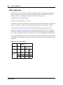
IP telephones
Complete this section if you are installing IP telephones.
Table 7 IP telephone provisioning
Prerequisites
7.a Are IP connections and IP addresses available for all IP telephones?
7.b If DHCP is not being used, has all telephone configuration been documented and
made available for telephone installers?
Hint: Use the Programming Record form.
7.c If DHCP is not being used, or if you want to enter the port manually, has the VLAN
port number been supplied, if one is being used on the switch?
7.d Have telephone power and connectors been provisioned?
7.e Do computers that will be using the Nortel Networks i2050 Software Phone meet the
minimum system requirements, including headset?
NetVision wireless telephones
Refer to “Gathering system information before you start” on page 53.
P0937663 03.1
Yes
No
31
Chapter 3
Installing IP telephones
An IP telephone converts the voice signal into data packets and sends these packets directly to
another IP telephone or to the Business Communications Manager over the LAN or the internet. If
the destination is an IP telephone, the arriving voice packets are converted to a voice stream and
routed to the speaker or headset of the target telephone. If the destination is the Business
Communications Manager, the voice stream is routed to a circuit switched connection, such as a
telephone (internal) or line (external PSTN or private network), or some form of gateway (VoIP).
Note: IP telephones require an IP network to reach the Business Communications
Manager. However, they do not need to use VoIP trunks to communicate beyond the
Business Communications Manager. They can use any type of trunk in the same way that
digital telephones do.
Before setting up IP clients, you must enable keycodes for IP telephony. For information on
entering keycodes, see the Keycode Installation Guide.
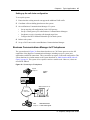
Supporting IP telephony
The Business Communications Manager supports two types of IP telephony protocols, UNISTIM
and H.323.
•
•
The Nortel Networks i-series telephones use UNISTIM.
The Symbol NetVision and NetVision Data telephones use H.323+. Refer to Chapter 4,
“Installing NetVision telephones,” on page 51.
The applications that control these protocols on the Business Communications Manager provide
an invisible interface between the IP telephones and the digital voice processing controls on the
Business Communications Manager.
About Nortel Networks IP telephones
The i2002 and i2004 telephones are hardwired to an internet connection. They can be installed on
any internet connection that has access to the network connected to the LAN or WAN of the
Business Communications Manager.
The Nortel Networks i2050 Software Phone runs on any computer running Windows 98 or
Windows 2000. The computer must be connected to the LAN or WAN that the Business
Communications Manager is connected to.
IP Telephony Configuration Guide
32
Chapter 3
Installing IP telephones
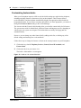
Configuring Nortel Networks i-series telephones
The configuration menus for the Nortel Networks i-series IP telephones (i2002, i2004, i2050) are
under Services, IP Telephony, Nortel IP Terminals and Services, Telephony Services, System
DNs, Inactive DNs (or Active set DNs, once the telephone connects to the system).
This section describes how to:
•
•
•
prepare the Business Communications Manager to receive IP telephone registration
install the IP telephone on site
perform the configuration process at the telephone
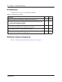
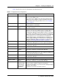
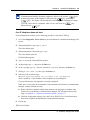
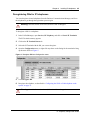
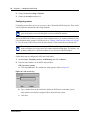
Preparing your system for IP telephone registration
When you install an IP telephone on a Business Communications Manager, you must activate
terminal registration on the Business Communications Manager. If this is your first installation,
you need to set the general parameters for IP registration.
Note: For the simplest installation possible, set telephone Registration and
Auto Assign DNs to ON, and leave Password blank. IP telephones installed on the
system LAN will connect and boot-up without manual registration.
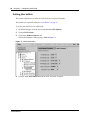
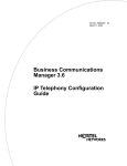
1
In Unified Manager, open Services, IP Telephony, and Nortel IP Terminals.
2
Select the General tab. Refer to Figure 4 on page 33.
3
Set Registration to ON to allow new IP clients to register with the system.
Caution: Security note
Set Registration to Off when you are not registering telephones.
4
In the Password box, type a password (Default: bcmi).
The installer enters this password on the IP telephone to connect to the Business
Communications Manager. If this field is left blank, there is no prompt during registration.
Note: The password can be changed to an alphanumeric string of a maximum of 10
characters.
5
Set the Auto Assign DN box.
• If Auto Assign DNs is set to ON, the Business Communications Manager system assigns a
free DN to a set being registered instead of prompting the installer for the set DN.
• If Registration and Auto Assign DNs are both set to ON, and the Registration password is
blank.
First-time-connected IP clients are assigned a DN without requiring installer intervention.
The system selects this number from the digital telephone DN range. Once the set is
registered, clicking the IP Terminal Status tab to determine which DN has been assigned.
P0937663 03.1
Chapter 3
Installing IP telephones
33
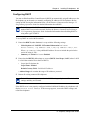
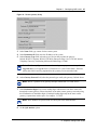
6
In the Advertisement/Logo box, type a string of text characters. This message is displayed on
the first line of the telephone display. The text string can be a maximum of 24 characters.
7
From the Default Codec menu, select a default Codec, or leave the Default Codec at Auto.
This is the Codec that is used if an IP telephone has not been configured with a preferred
codec. For information about choosing a codec, refer to “Choosing a codec” on page 33.
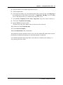
8
From the Jitter Buffer menu, select a Jitter Buffer level.
For information about choosing a Jitter Buffer, refer to “Choosing a Jitter Buffer” on page 34.
Figure 4 Set registration properties
Choosing a codec
The default codec is used when an IP client has not been configured to use a preferred Codec.
Refer to the next section for individual IP client Codec settings. If the default Codec is set to
AUTO, the Business Communications Manager will choose the appropriate CODEC when an IP
client makes a call. For example, if both endpoints of the call are IP telephones on the same subnet,
the Business Communications Manager chooses G.711 for maximum voice quality. If the
telephones are on different subnets, the Business Communications Manager will choose G.729 to
minimize network bandwidth consumption by voice data packets.
For IP telephones, the Business Communications Manager supports both a-law and mu-law
variants of the G.711 CODEC, as well as the G.729 and G.723 CODECS.
•
The G.711 CODEC samples the voice stream at a rate of 64Kbps (Kilo bits per second), and is
the CODEC to use for maximum voice quality.
•
The G.729 CODEC samples the voice stream at 8Kbps. The voice quality is slightly lower
using a G.729 but it reduces network traffic by approximately 80%.
The G.723 CODEC should be used only with third party devices that do not support G.729 or
G.711.
•
IP Telephony Configuration Guide
34
Chapter 3
Installing IP telephones
Choosing a Jitter Buffer
A jitter buffer is used to prevent the jitter associated with arriving (Rx) voice packets at the IP
telephones. The jitter is caused by packets arriving out of order due to having used different
network paths, and varying arrival rates of consecutive voice packets.The greater the size of the
jitter buffer, the better sounding the received voice appears to be. However, voice latency (delay)
also increases. Latency is very problematic for telephone calls, as it increases the time between
when one user speaks and when the user at the other end hears the voice.
The administrator can adjust the default jitter buffer size to the following values:
•
•
•
•
•
NONE:
AUTO:
SMALL:
Minimal latency, best for short-haul networks with good bandwidth.
Business Communications Manager will dynamically adjust the size.
Business Communications Manager will adjust the buffer size, depending on
CODEC type and number of frames per packet to introduce a 60-millisecond
delay.
MEDIUM: 120-millisecond delay
LARGE: 180-millisecond delay
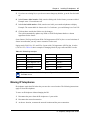
Installing i-series telephones
The Nortel Networks i-series telephones can be configured to the network by the end user or by the
administrator. If the end user is configuring the telephone, the administrator must provide the user
with the required parameters.
A maximum of 90 IP telephones, including Nortel Networks i2050 Software Phones, and H.323
devices, can be connected on the Business Communications Manager system.
Before installing
Before installing the i2002 or i2004 telephone, ensure that:
•
•
•
•
ensure the telephone has the appropriate power supply for your region
if powered locally, ensure the installation site has a nearby power outlet;
otherwise, it can be powered through a Power Inline Patch Panel (PiPP)
the installation site has a 10/100 BaseT Ethernet connection
if you are not using the 3-port switch, you have 10/100 BaseT Ethernet connections for both
the telephone and for your computer equipment.
Caution: Do not plug the telephone into an ISDN connection. This can cause severe
damage to the telephone. Plug the telephone only into a 10/100 BaseT Ethernet connection
P0937663 03.1
Chapter 3
Installing IP telephones
35
Using a 3-port switch
In an office environment where a LAN network already exists, most computers will already be
connected to a LAN line. To avoid the necessity of installing duplicate network connections, you
can use a Nortel Networks 3-port switch for each i2002 and i2004 telephone. This switch allows
the telephone and computer to connect to the same network connection. For more information,
consult the i2002/i2004 and the 3-way switch documentation.
Connecting the i2002 or i2004 telephone
Follow these steps to connect an i2002 or i2004 telephone:
1
Connect one end of the handset cord to the handset jack on the telephone base. Connect the
other end of the handset cord to the handset.
2
Connect one end of a Cat-5 line cord with RJ45 connectors to the line cord jack on the
telephone base. Connect the other end of the line cord to the Ethernet connection or to the
3-way switch connector.
3
Plug the AC Power adapter into the base of the telephone, and then plug the adapter into the
AC outlet.
Configuring the i2002 or i2004 telephone to the system
Configuring IP telephones involves two processes:
•
•
If DHCP service on the BCM is active or the Customer DHCP server has been configured to
hand out the specific BCM details, the IP telephone will automatically attempt to find the
server. Once you register the telephone to the system, as described in “Registering the
telephone to the system”, the telephone assumes the parameters it receives from the system,
which are described in “Configuring telephone settings”.
If DHCP is not configured to provide system information, or if you are not using DHCP on
your network, you need to configure your telephone parameters before the telephone can
register to the system. In this case, follow the directions in “Configuring telephone settings”,
and then follow any of the prompts that appear, as described in “Registering the telephone to
the system”.
Registering the telephone to the system
When you first connect the telephone to the IP connection, you may receive one of the following:
•
•
•
•
If the telephone is not yet registered, and if a password was entered in the Terminal
Registration screen, the telephone prompts you for that password.
If you set Auto Assign DN on the Business Communications Manager to OFF, the telephone
prompts you for a DN.
If you are prompted for a password, enter the password and press OK.
If you are prompted for a DN, enter the DN you want assigned to this telephone and press OK.
IP Telephony Configuration Guide
36
Chapter 3
Installing IP telephones
When the telephone registers, it downloads the information from the Business Communications
Manager IP Telephony record to the telephone configuration record.
Note: If the telephone displays a prompt that indicates it cannot find the server,
follow the instructions in “Configuring telephone settings” to enter the specific
network path.
Once registration has completed, you do not need to go through the registration steps described
above unless you deregister the terminal. For information about setting the registration settings,
see “Preparing your system for IP telephone registration” on page 32.
Configuring telephone settings
If you are not automatically registered to the Business Communications Manager, you can
configure your telephone settings to allow you to access a system on the network. You will also
need to perform these steps if your IP telephone is not connected to the same LAN that the
Business Communications Manager is connected to.
Follow these steps to access the local configuration menu on an i2002 or an i2004 telephone:
1
Restart the telephone by disconnecting the power, then reconnecting the power.
After about four seconds, the top light flashes and NORTEL NETWORKS appears on the screen.
2
Immediately, when the greeting appears, quickly press the four display keys, one at a time,
from left to right. These keys are located directly under the display.
These keys must be pressed one after the other within 1.5 seconds or the telephone will not go
into configuration mode.
• If Manual Cfg DHCP(0 no, 1 yes) appears on the screen, you successfully accessed the
configuration mode.
• If any other message appears, disconnect, then reconnect the power, and try to access the
configuration mode again.
3
Enter the network parameters, as prompted.
As each parameter prompt appears, use the keypad to define values.
Use the • key to enter the period in the IP addresses.
Press OK to move forward.
P0937663 03.1
Chapter 3
Installing IP telephones
37
Table 8 describes the value for each parameter and what they mean.
Table 8 IP telephone server configurations
Field
Value
Description
DHCP
0 or 1
Enter 0 if not using a DHCP server to dispense IP addresses.
Enter 1 if using a DHCP server.
If you choose to use a DHCP server rather than allocating static IP
addresses for the IP telephones, skip the remainder of this section.
For information about setting up a DHCP server, see “Configuring
DHCP” on page 41.
SET IP
<ip address>
The set IP must be a valid and unused IP address on the network
that the telephone is connected to.
NETMASK
<subnet mask
address>
This is the subnet mask. This setting is critical for locating the system
you want to connect to.
DEF GW
<ip address>
Default Gateway on the network (i.e., the nearest router to the
telephone. The router for IP address W.X.Y.Z is usually at W.X.Y.1)
If there are no routers between the telephone and the Business
Communications Manager network adaptor to which it is connected,
(for example a direct HUB connection), then enter the Published IP
address of the Business Communications Manager as the DEF GW.
If the IP telephone is not connected directly to the Published IP
address network adaptor, set the DEF GW to the IP address of the
network adaptor the telephone is connected to. For information on
setting the published IP address of the Business Communications
Manager, see “Defining published IP address” on page 28.
S1 IP
<ip address>
This is the Published IP address of the first Business
Communications Manager that you want to register the telephone to.
S1 PORT
Default: 7000
This is the port the telephone will use to access this Business
Communications Manager.
S1 ACTION
Default: 1
S1 RETRY COUNT
<digits between 0
and 255>
Set this to the number of times you want the telephone to retry the
connection to the Business Communications Manager.
S2 IP
<ip address>
This is the Published IP address of the second Business
Communications Manager that you want to register the telephone to.
It can also be the same as the S1 setting.
S2 PORT
Default: 7000
This is the port the telephone will use to access this Business
Communications Manager.
S2 ACTION
Default: 1
S2 RETRY COUNT
<digits between 0
and 255>
Set this to the number of times you want the telephone to retry the
connection to the Business Communications Manager.
VLAN
0: No VLAN
1: Manual VLAN
2: Automatically
discover VLAN
using DHCP
If you have DHCP set to yes, you can select number 2 if you want the
system to find the VLAN port assigned to the telephone.
If you do not have DHCP, or if you want to set the VLAN port number
manually, select number 1.
If VLANs are not used on your network, select 0.
IP Telephony Configuration Guide
38
Chapter 3
Installing IP telephones
When you have entered all the configuration information, the telephone attempts to connect to
the Business Communications Manager. The message Locating Server appears on the
display. If the connection is successful, the message changes to Connecting to Server
after about 15 seconds. Initialization may take several minutes. Do not disturb the telephone
during this time.
Once the telephone connects to the server, the display shows the DN number and a date
display. As well, the six keys at the top of the display are labelled.The telephone is ready to
use.
Note: If the DN record has not yet been configured, as will be the case with auto-assigned
DNs, you will only be able to make local calls, until other lines have been assigned.
Note: If the telephone has not been registered before, you will receive a New Set
message. Enter the information you are prompted for. Refer to “Registering the telephone
to the system” on page 35.
Troubleshooting an IP telephone
If the system is not properly configured, several messages can appear, as listed in Table 9.
Table 9 IP telephony display messages
Message
Description/Solution
SERVER: NO PORTS LEFT
The Business Communications Manager has run out of ports. This message
will remain on the display until a port becomes available and the telephone is
powered down then powered up.To obtain more ports, you may need to install
additional keycodes. See the Keycode Installation Guide.
Invalid Server Address
The S1 is incorrectly configured with the IP address of a Business
Communications Manager network adapter other than the published IP
address.
Registration Disabled
The Registration on the Business Communications Manager is set to OFF.
INCOMING PACKET LOSS
While on a call, the number of voice packets is less than expected.
This message may appear occasionally in normal circumstances. In this case,
the message can be ignored.
If the message appears frequently or does not go away, it indicates that the far
end voice packets are not being properly routed. Ask your system administrator
to check the configuration settings for any NAT, DHCP server, firewall and
router between the telephone and the far end.
Note: The IP telephone monitors the number of incoming voice packets every
five seconds.
SERVER UNREACHABLE.
RESTARTING . . .
Check that you have entered the correct Netmask and gateway IP addresses.
If the settings are correct, contact your system administrator.
NEW SET
The telephone has not been connected to the Business Communications
Manager before, and must be registered.
P0937663 03.1
Chapter 3
Installing IP telephones
39
Note: To see the configuration information of a telephone connected to the Business
Communications Manager: When the telephone is not on a call, press the
key
(bottom-right corner of the telephone), followed by the
key (next to the
key). The display will automatically scroll through the configuration settings.
To see the Codec data for a telephone while it is on a call: Press the
followed by the
key,
key.
If an IP telephone does not boot
If the telephone does not boot, use the following procedure to check the UTPS log.
1
Use Telnet (Diagnostics, Tools, Telnet) to access the Business Communications Manager file
system.
2
When prompted for Login, type ee_admin.
This is the default login.
3
When prompted for a Password, type eedge.
This is the default password.
The Main Menu appears.
4
Type 7 to access the Command Line interface.
5
At the prompt, type: e: then press the Enter key.
6
At the e: prompt, type: cd \NORTEL NETWORKS\Logs\Nnu then press the Enter key
7
Then type: edit UTPS.log then press the Enter key.
8
In the log, look for this message:
Opening signaling channel for set index X [at <ip address>]
where <ip address> is the IP address of the telephone you just configured.
If you get this message, the telephone is correctly configured.
If this entry is not present, the IP telephone is not connected to the Business Communications
Manager, continue with the next step.
9
a
Double check the telephone configuration parameters by pinging the telephone using
Telnet to access the Business Communications Manager. For information about using
Ping, see Appendix C, “Network performance utilities,” on page 117.
b
Check the configuration settings of any NAT server, DHCP server, firewall and routers
between the telephone and the Business Communications Manager.
Exit the log.
10 Exit from Telnet.
IP Telephony Configuration Guide
40
Chapter 3
Installing IP telephones
Telephone does not connect to system
If an IP telephone does not display the text Connecting to server within two minutes after
power up, the telephone was unable to establish communications with the Business
Communications Manager. Double check the IP configuration of the telephone, and the IP
connectivity to the Business Communications Manager (cables, hubs, etc.).
Slow connection
If the connection between the IP client and the Business Communications Manager is slow (ISDN,
dialup modem), change the preferred CODEC for the telephone from G.711 to G.729. See “IP
telephone server configurations” on page 37.
One-way or no speech paths
Signaling between the IP telephones and the Business Communications Manager uses Business
Communications Manager port 7000. However, voice packets are exchanged using the default
RTP ports 28000 through 28255 at the Business Communications Manager, and ports 51000
through 51200 at the IP telephones. If these ports are blocked by the firewall or NAT, you will
experience one-way or no-way speech paths.
Dropped voice packets
If the LAN traffic in your network environment is heavy, you may experience dropped voice
packets. If this occurs, connect the Business Communications Manager and the telephones to a
local network hub to avoid the network traffic.
The IP telephone monitors the number of incoming voice packets that arrive every five seconds
during a call. If the number of packets becomes less than expected, the user will receive either
broken transmissions or silence. The telephone will display an INCOMING PACKET LOSS
message for three seconds. If the message is transitory, there is no concern. If the message appears
continuously, it indicates that the voice packets from the sending telephone are not properly
routing over the network. Check the configuration settings of any NAT server, DHCP server,
firewall, and router between the telephone and the sending telephone.
Changing the contrast level
When an IP telephone is connected for the first time, the contrast level is set to the default setting
of 1. Most users find this value is too low. Therefore, after the telephone is operational, you can
increase the contrast level by pressing Feature •‡ at the telephone.
P0937663 03.1
Chapter 3
Installing IP telephones
41
Configuring DHCP
You can use Distributed Host Control Protocol (DHCP) to automatically assign IP addresses to the
IP telephones as an alternative to manually configuring IP addresses for IP telephones. Before
setting up DHCP using the information below, see the Business Communications Manager 2.5
Programming Operations Guide for detailed information about DHCP.
Note: Do not enable DHCP on the Business Communications Manager if you have
another DHCP server on the network. Refer to the Business Communications Manager
2.5 Programming Operations Guide for detailed information about disabling DHCP or
using other types of DHCP.
To set up DHCP to work with IP terminals:
1
Ensure that DHCP (under Services) is set up with the following settings:
•
Global Options tab: NORTEL IP Terminal Information box is set to:
Nortel-i2004-A, <ip address>:7000,1,250;<ip address>:7000,1,250.
Where <ip address> is the published IP address. Be sure to include the period at the
end of the string (1,250.).
•
2
Summary tab: Status box is set to Enabled.
Ensure that the DHCP LAN settings are correct (DHCP, Local Scope, LANX, where LANX
is a LAN that contains IP sets that use DHCP):
•
Scope Specific Options tab:
Scope Status: Enabled
Default Gateway Field: <Published IP Address>
• Address Range tab: contains the range of IP addresses you need.
3
Restart all existing connected IP telephones.
Note: Whenever changes are made to the DHCP settings, telephones will retain the old
settings until they are restarted.
If the DHCP server is not properly configured with the Published IP address, the telephones will
display Invalid Server Address. If this message appears, correct the DHCP settings, and
restart the telephones.
IP Telephony Configuration Guide
42
Chapter 3
Installing IP telephones
Modifying settings for Nortel IP telephones
Settings such as jitter buffers and codecs for the Nortel IP telephones including the i2050, i2002
and i2004 can be modified through the Unified Manager:
1
In the Unified Manager, open Services, IP Telephony, and click on Nortel IP Terminals.
The IP Terminal summary appears.
2
Click on the IP Terminal Status tab.
On the IP Terminal status screen, every IP telephone currently connected to the Business
Communications Manager occupies a row in the IP Terminal Status table. Refer to Figure 5.
Figure 5 IP Terminal status
3
Select the IP Terminal that you want to change the properties for.
4
Open the Configuration menu, or right-click anywhere on the terminal listing to open the
Configuration menu. Refer to Figure 6.
Figure 6 Configuration menu
P0937663 03.1
Chapter 3
5
Installing IP telephones
43
From the menu, select Modify Codec/Jitter Buffer.
The IP Terminal Status dialog box appears. Refer to Figure 7.
Figure 7 IP Terminal status dialog
6
From the Codec menu, select a Codec.
Specifying a non-default CODEC for a telephone allows you to override the general setting.
You might, for example, want to specify a low bandwidth CODEC (g.729) for a telephone that
is on a remote or busy sub-net.
7
From the Jitter Buffer menu, select a jitter buffer value.
Increase the jitter buffer size for any telephone that has poor network connectivity to the
Business Communications Manager.
IP Telephony Configuration Guide
44
Chapter 3
Installing IP telephones
Download firmware to a Nortel IP telephone
Firmware is the software stored in the telephone. When the Business Communications Manager is
upgraded with a new IP telephone firmware load, this firmware load will automatically be
downloaded into the IP telephones when they next connect to the Business Communications
Manager.
You can use the Force firmware download option under the Configuration menu (Nortel IP
Terminals) to force immediate download to a telephone. You would do this in situations where
you suspect that a particular telephone has corrupted firmware.
Follow these steps to force a firmware download to a telephone:
1
In the Unified Manager, open Services, IP Telephony, and click on Nortel IP Terminals.
The IP Terminal summary appears.
2
Click on the IP Terminal Status tab.
3
Select the IP telephone that you want to download firmware to.
4
Open the Configuration menu, or right-click anywhere on the listing for the terminal to bring
up the menu. Refer to Figure 8
Figure 8 Configuration menu
5
Select Force Firmware Download.
A dialog appears asking if you want to confirm that you want to proceed.
6
Click the Yes button.
The firmware download begins.
The system drops any active call on that telephone, and downloads a new firmware load into the
selected telephones. The telephones will be unusable until the download is completed and the
telephones have reset.
Note: In order not to saturate the IP network with download packets, the system will only
download up to five IP telephones at any given time. Telephones requiring download will
show a Unified Manager status of Download Pending, and the UNISTIM Terminal
Proxy Server (UTPS) will initiate download as resources become available.
P0937663 03.1
Chapter 3
Installing IP telephones
45
Deregistering DNs for IP telephones
You can deregister selected telephones from the Business Communications Manager, and force
the telephone to go through the registration process again.
Warning: Once this feature is activated, all active calls are dropped.
To deregister a DN for a telephone:
1
In the Unified Manager, open Services, IP Telephony, and click on Nortel IP Terminals.
The IP Terminal summary appears.
2
Click on the IP Terminal Status tab.
3
Select the IP Terminal with the DN you want to deregister.
4
Open the Configuration menu, or right-click anywhere on the listing for the terminal to bring
up the menu. Refer to Figure 9.
Figure 9 Deregister DN from Configuration menu
5
Click Deregister DN.
6
Reregister the telephone, as described in “Configuring the i2002 or i2004 telephone to the
system” on page 35.
Warning: Once this feature is activated, all active calls are dropped.
IP Telephony Configuration Guide
46
Chapter 3
Installing IP telephones
Customizing feature labels
When your IP telephone acquires a DN record, the default settings are applied to the telephone,
including assigning features to the memory keys on the telephone. These features all have
pre-defined labels, and the telephone automatically displays the appropriate labels beside the
programmed buttons. If you want to customize these labels to be more appropriate, you can do so
through the Feature Labels heading on the Unified Manager.
The screens under the Feature Labels heading allow you to define custom labels for 24 features.
The system comes with 10 default labels, which are feature and language-specific, depending on
which region your system was assigned. The default labels are mainly messaging and call
attendant features.
However, you can change any other feature label by adding to this list, or deleting any of the
default settings and inserting new codes and labels.
Follow these steps to change the features or labels on the memory buttons on your IP telephone:
1
Click on the keys beside Telephony Services, General, Nortel IP terminals, and
Feature labels.
2
Click on the label set you want to view.
The Labels <label number> screen appears.
Figure 10 Label set 1-6, voicemail defaults
P0937663 03.1
Chapter 3
Installing IP telephones
47
3
If you have an existing list, or you do not want to change any defaults, go to the first free label
set.
4
In the Feature <label number> field, enter the dialing code for the feature you want to relabel.
Example: enter 3 for conference call
5
In the Label <label number> field, enter the new label you want the telephones to display.
Example: The current label for feature code 3 is Conference, you could change it to Conf Call
6
Click anywhere outside the field to save the changes.
The system automatically updates any i2004 or i2050 IP telephones that have a button
appearance for the feature.
Some features, like Page and System Wide Call Appearances (SWCA), have several variations of
feature invocation that you may want to customize for the users.
Paging can be F60, F61x, F62, and F63x. System-wide Call Appearance (SWCA) has 16 codes
(*520 to *535). Table 10 shows examples of changing labels for page codes and SWCA codes:
Table 10 Relabelling examples
Feature code
New label
Feature code
New label
60
Gen Page
*520
SW Call 1
610
Pg Every
*521
SW Call 2
61
Zone <digit from 1-9>
*522
SW Call 3
62
Speak Pg
*530
SW Call 4
630
Speak, All
*531
SW Call 5
Note: Line names are defined when you configure the line, and can be changed through
the Lines menus.
Moving IP telephones
IP telephones retain their DN when they are moved to a new location. The following instructions
apply to Nortel IP telephones.
To move an IP telephone without changing the DN:
1
Disconnect the power from the IP telephone or 3-port switch.
2
Disconnect the network connection.
3
At the new location, reconnect the network location and the power connection.
IP Telephony Configuration Guide
48
Chapter 3
4
Installing IP telephones
If the new location is on a different LAN or WAN from the old location, the subnet mask,
default gateway IP, S1 IP, and S2 IP may change. If this is the case, you must change the
settings for the telephone. To do this, see “Connecting the i2002 or i2004 telephone” on page
35. Do not change the Set IP Address.
To move a Nortel IP telephone and change the DN:
1
Deregister the DN, using the instructions in “Deregistering DNs for IP telephones” on page
45.
2
Disconnect the network connection and the power connection from the telephone.
3
Reinstall the phone at the new location. For information about this, see “Connecting the i2002
or i2004 telephone” on page 35.
Keep DN alive
This feature is only relevant to the i-series IP telephones (Model i2004/i2002/i2050).
If you want to retain DN-specific features such as Call Forward No answer and Call Forward on
Busy if an IP telephone becomes disconnected, you must ensure the following setting is set to Y.
1
Find the DN record for the IP telephone.
2
Click the Capabilities heading.
3
Beside the Keep DN alive field, choose Y.
Choosing N for this field allows the DN record to become inactive if the IP telephone is
disconnected. This produces a Not in Service prompt if any of the special features, such as
Call Forward, are invoked.
Warning: If the system is reset while an IP telephone is disconnected, the Keep DN alive
feature becomes inactive until the telephone is reconnected.
Note: When an IP telephone is disconnected, there is about a 40-second delay before the
system activates Keep DN alive during which incoming calls will either get a busy signal
or be rerouted to the Prime set, depending on how your system is programmed. The same
type of delay occurs when the IP telephone is reconnected to the system.
P0937663 03.1
Chapter 3
Installing IP telephones
49
Configuring the Nortel Networks i2050 Software Phone
The Nortel Networks i2050 Software Phone allows you to use a computer equipped with a sound
card, microphone, and headset to function as an IP terminal on the Business Communications
Manager system. The Nortel Networks i2050 Software Phone uses the computer IP network
connection to connect to the Business Communications Manager.
When you install the Nortel Networks i2050 Software Phone, on-screen documentation walks you
through the steps for installing the software. You can also refer to the i2050 Software Phone
Installation Guide.
To configure the Nortel Networks i2050 Software Phone to connect to the Business
Communications Manager:
1
Click the Start button and then click Settings.
2
Click Control Panel.
3
Double click the i2050 Software Phone icon.
The utility opens to the Communications Server tab. Refer to Figure 11.
Figure 11 i2050 Communications server
4
Enter the Published IP address of the Business Communications Manager in the IP address
field.
5
In the Port drop down menu, select BCM.
6
Select the Server Type tab. Refer to Figure 12.
Figure 12 i2050 Switch type
IP Telephony Configuration Guide
50
Chapter 3
Installing IP telephones
7
Click on the BCM option.
8
Enable the Select Sound Devices tab for the USB headset.
To further configure this device through Unified Manager, see “Modifying settings for Nortel IP
telephones” on page 42.
P0937663 03.1
51
Chapter 4
Installing NetVision telephones
This chapter describes how to configure the Symbol NetVision handsets to the Business
Communications Manager system.
NetVision connectivity
The Business Communications Manager supports access points, NetVision handsets and other
wireless IP devices that use either IEEE 802.11 (1 or 2 M-bits/sec, Frequency Hopping Spread
Spectrum) or IEEE 802.11B (11 M-bits/sec, Direct Sequence Spread Spectrum) technology.
NetVision telephones use an enhanced version of H.323, referred to as H.323+.
NetVision and NetVision Data wireless IP telephones connect to the Business Communications
Manager over a LAN through the Business Communications Manager LAN or WAN card. The
Business Communication Manager sees these telephones as IP telephones, which means that the
DN records are assigned from the digital range rather than the Companion or ISDN range of DNs.
The default codec for NetVision handsets is G.729. However, if the NetVision handsets connect
over IP trunks, the codec of the IP trunk takes precedence.
Note: NetVision handsets experience communications problems if your system has a
NAT between the handset internet connection and the published address of the Business
Communications Manager LAN. For this reason, this configuration is NOT supported.
From within the system, the handsets can make and receive calls from any trunk type supported by
the system, which can include voice over IP (VoIP), digital and analog trunks. The handset DN
record determines which lines the handset can access.
The handset can communicate with any other type of telephone supported by the Business
Communications Manager system.
Access points
Instructions about installing the access point are provided with the access point equipment, which
is sold and installed separately. The access point is set up with a unique identifier (ESS ID) which
is entered into the handset either through a configuration download or manually through the
dialpad to allow the handset to access the system through that access point.
Keycodes
Before setting up NetVision telephones, you must enable keycodes for IP telephony. For
information on entering keycodes, see the Keycode Installation Guide.
IP Telephony Configuration Guide
52
Chapter 4
Installing NetVision telephones
Handset and call functions
Symbol supplies a handset user guide that describes the features on the NetVision handset and how
to use them to perform basic functions.
The Business Communications Manager NetVision Feature card explains how to use the handset
to access features on the Business Communications Manager system and provides some quick tips
for basic call functions.
The Business Communications Manager Telephone Feature Programming Guide provides
information about how to use Business Communications Manager call features and includes a list
of supported features for the NetVision telephone.
Configuring NetVision records
This section provides the steps for configuring the various records the NetVision telephone
requires to work on a Business Communications Manager system.
This section describes:
•
•
What information you require before you configure your handsets (“Gathering system
information before you start” on page 53)
How to set up an H.323 Terminals record on the Business Communications Manager to allow
the NetVision handset to connect to the system (“Assigning H.323 Terminals records” on page
53)
Note: DN records for NetVision handsets are created in the same way as for all other
telephones on the system. The various settings for DN records are described in the
Business Communications Manager Programming Operations Guide.
Choose model IPWls, when configuring NetVision records.
•
Use the NetVision Phone Administrator (NVPA) application to configure the handset features.
Refer to the Business Communications Manager 2.5 NetVision Phone Administrator Guide.
P0937663 03.1
Chapter 4
Installing NetVision telephones
53
Gathering system information before you start
Ensure the following is complete, or the information is on hand before you start configuring your
NetVision telephones:
1. The Business Communications Manager has been set up to allow
IP telephones.
Refer to Chapter 2,
“Prerequisites checklist,” on
page 25.
2. If you are configuring the Business Communications Manager
records before you configure the handset: You know which DNs
you want to assign to the handsets and you have all the line,
restrictions, and telephony information you require to create or
update a DN record for each telephone.
DN records
3. You have downloaded the NVPA application and NetVision Phone Download the latest version of
Administrator Guide, which provides a list of the information you the NetVision Phone
require to fill out that tool for each handset.
Administrator
http://www.symbol.com/services/downloads/nvfirmware2.html
4. You have obtained the Symbol NetVision serial cable, which is used to
transfer configuration information between the computer where the tool is
installed and the handset.
Purchased from Symbol at <http:/
5. You have a list of names that you will use for the handsets. Each name
must be unique to a handset. Both the H.323 Terminals record and the
NVPA record must have exactly the same name.
Name field
6. You have identified a PIN for each handset.
Password field
/symbol.com>
(part number: 25-20528-01)
Assigning H.323 Terminals records
The H.323 Terminals record (Services, Telephony Services, IP Telephony) identifies the
NetVision handsets within the Business Communications Manager. The Business
Communications Manager uses the information from this file to determine if the handset will be
allowed to connect to the system. When you configure the handset with the NVPA file, the Name
and PIN that you use, must match what is in the H.323 Terminals record.
Notes
The following are some notes about the process of configuring handsets to the Business
Communications Manager.
•
You must have an H.323 record configured before you configure the handsets with the Nortel
NVPA.
•
If you do not specify a DN in the H.323 record, one will automatically be assigned to the
handset. If you specified a DN record, it will appear under the Active DNs heading once the
handset connects to the system. If you want to specify a range of DNs, you can use the Add
IP Telephony Configuration Guide
54
Chapter 4
Installing NetVision telephones
Users Wizard. This wizard is explained in the Business Communications Manager 2.5
Programming Operations Guide.
•
You need to set up the DN record to determine what lines the handset can access and how it
will behave on the system.
•
The Name you specify in the H.323 record must match the User Name you specify in the
Nortel NVPA tool, otherwise, the handset will not be allowed to connect to the Business
Communications Manager.
If you need to change the H.323 Terminals record, refer to “Updating the H.323 terminals record”
on page 56 and “Deleting a NetVision telephone from the system” on page 57. If you require
information about changing the DN records, refer to the Business Communications Manager 2.5
Programming Operations Guide for details.
Adding a NetVision record in the Unified Manager
Follow these steps to preconfigure an H.323 Terminals record for each handset you want to
install:
1
In the Unified Manager, open Services, IP Telephony, and click on H.323 Terminals.
The H.323 terminal list appears.
2
On the top menu, click Configuration, and then click Add Entry.
The H.323 Terminal List dialog appears. Refer to Figure 13.
Figure 13 H.323 Terminal list dialog
P0937663 03.1
Chapter 4
3
Installing NetVision telephones
55
In the Name field, type in the name of the user of the handset.
Note: This is the same name that you will enter in the Nortel NVPA configuration record
for the User Name of the handset. This name must be unique within the first seven
characters for each handset, and can be a maximum of 10 characters.
4
In the DN field, type in the DN record number that you configured for the handsets.
If you want the system to assign a DN record, enter a 0 (zero) in this field.
Note: The DN field cannot be left blank.
5
In the Password field, enter a unique password that the user will need to enter to use the
handset.
You must enter at least four digits. This is a mandatory field.
6
Click Save.
Note: Shortly after the H.323 Terminals record is saved, the system moves the DN you
specified to the Active DNs list. If you have not already done so, configure the DN record
for user requirements. If you are not sure about how to configure DNs, refer to the
Business Communications Manager 2.5 Programming Operations Guide for details about
the various settings within this record.
Programming note: Ensure that you choose Model IPWls on the General screen.
7
Use the Nortel NVPA application to configure and download a record for each handset.
8
When the handsets have received the downloaded NVPA record, they will be read to connect
to the Business Communications Manager system.
Note: The IP Address and Status fields on the H.323 Terminals record will
automatically update when the configured handset first contacts the system.
Testing the handset functions
When the handset is registered, check the handset feature menu, and test the handset to ensure it is
working as you expected. Refer to the NetVision Telephone Feature User Card for directions
about using Business Communications Manager call features on the NetVision handset.
IP Telephony Configuration Guide
56
Chapter 4
Installing NetVision telephones
Updating the H.323 terminals record
If you need to change the password for a NetVision telephone, you can update the H.323 terminals
record.
Follow these steps to update the H.323 Terminals record:
1
In the Unified Manager, click on the keys beside Services and IP Telephony.
2
Click on H.323 Terminals.
3
On the H.323 Terminal List screen, highlight the terminal you want to change.
4
At the top of the page, click on Configuration menu and select Update Entry.
The H.323 Terminal List dialog appears.
Figure 14 H.323 Terminal List dialog
5
Enter a new password.
6
Click Save.
P0937663 03.1
Chapter 4
Installing NetVision telephones
57
Changing a handset Name
The Name is the primary point of recognition for the Business Communications Manager to
identify a handset. If you need to change the name of an assigned handset:
1
Delete the existing record. Refer to “Deleting a NetVision telephone from the system” on page
57.
2
Enter a new record with the new name.
You can assign the existing DN to the new record. For security purposes, you should assign a
new Password.
3
Update the handset configuration by updating the Nortel NVPA record for the handset, and
downloading the new configuration to the handset. When the handset reconnects to the
system, the new H.323 record will take effect.
Changing the DN record of a handset
If you need to change the DN for a handset, use the Unified Manager (Services, Telephony
Services, General, Change DN). The change will automatically be reflected in the
H.323 Terminals record for the handset.
When you use the Change DN feature, the DN settings are transferred to the new DN and the
system features remain active on the new DN.
Warning: Deleting an H.323 Terminals record will remove the DN from the Active DNs
list. This means that system features such as Call Forward No Answer will also become
inactive.
Deleting a NetVision telephone from the system
If you want to stop a terminal from having access to the Business Communications Manager, you
can delete the DN record for the terminal:
1
In the Unified Manager, open Services, IP Telephony, and click on H.323 Terminals.
2
On the IP Terminal Status screen, select the terminal you want to change.
3
In the Configuration menu, click Delete Entry.
A query box appears.
IP Telephony Configuration Guide
58
Chapter 4
4
Installing NetVision telephones
Click Yes to delete the record.
Under the Systems DNs heading, the DN record returns to the Inactive DNs list.
Finding the Published IP address
If you are unsure about what the Published IP address of your system is, use the Unified Manager
to track it down:
To find out which data card is being used for the Public IP address:
1
Click the key beside Services.
2
Click on IP Telephony.
The right frame displays Published IP address device. Make a note of it.
3
Click on the key beside Resources.
4
Click the key beside device that was displayed in the first part of this process (LAN or WAN).
5
Click on the individual device (LAN 1, WAN 1 or WAN 2).
The IP address field displays the Published IP address that you use in the Nortel NVPA.
P0937663 03.1
59
Chapter 5
Configuring VoIP trunks
This chapter explains how to configure voice over IP (VoIP) trunks on a Business
Communications Manager. A VoIP trunk allows you to establish communications between a
Business Communications Manager and a remote system across an IP network.
Note: VoIP trunks can be used for calls originating from any type of telephone within the
Business Communications Manager system. Calls coming into the system over VoIP
trunks from other systems can be directed to any type of telephone within the system.
You cannot program DISA for voice over IP (VoIP) trunks, therefore, your system
features cannot be accessed from a remote location over a VoIP trunk.
Configuring a VoIP trunk requires the following actions:
•
•
•
•
Installing keycodes
Configuring media parameters
Outgoing call configuration
Incoming call configuration
Note: If you are using the Business Communications Manager with a Meridian 1
(M1-ITG) system, you must set up the system to be compatible with the M1. See
Appendix D, “Interoperability,” on page 119.
Installing keycodes
Before you can use VoIP, you must obtain and install the necessary keycodes. See the Keycode
Installation Guide for more information about installing the keycodes. Talk to your Business
Communications Manager sales agent if you need to purchase a VoIP keycode, or additional VoIP
keycodes.
Published IP address
You will require the public IP address to set up the gateways for VoIP trunks. Refer to “Defining
published IP address” on page 28 for details.
IP Telephony Configuration Guide
60
Chapter 5
Configuring VoIP trunks
Configuring media parameters
There are three steps to configuring media parameters:
•
•
•
Configuring codecs
Setting silence compression
Setting jitter buffers
Configuring codecs
This section explains how to select the codecs that are used for VoIP trunks. For an explanation of
codecs, refer to “Codecs” on page 22.
To configure the codecs:
1
In Unified Manager, click on the keys beside Services, IP Telephony.
2
Click on H.323 trunks.
3
Click on the Media Parameters tab.
The Media Parameters dialog appears. Refer to Figure 15.
Figure 15 Media parameters
4
Click the First Preferred Codec menu.
5
Select the codec you want to use as the first preferred codec.
This is the most preferred codec to be used on VoIP trunks.
6
For each preferred codec, select the codec you want to use.
P0937663 03.1
Chapter 5
Configuring VoIP trunks
61
Setting silence compression
This section explains how to set silence compression on VoIP trunks.
The silence compression feature identifies periods of silence in a conversation, and stops sending
IP speech packets during those periods. In a typical phone conversation, most of the conversation
is half-duplex, meaning that one person is speaking while the other is listening. If silence
compression is enabled, no voice packets are sent from the listener end. This greatly reduces
bandwidth requirements.
G.723.1 and G.729 support silence compression. If a conversation is using G.711, silence
compression does not occur.
To set the silence compression:
1
In Unified Manager, click on the keys beside Services, IP Telephony.
2
Click on H.323 trunks.
3
Click on the Media Parameters tab. The Media Parameters dialog appears.
Refer to Figure 16.
Figure 16 Media Parameters
4
Click the Silence Compression drop-down menu, and select either Enabled or Disabled.
If you select Enabled, silence compression is only used when a G.729 or G.723.1 codec is in
use.
IP Telephony Configuration Guide
62
Chapter 5
Configuring VoIP trunks
Setting jitter buffers
This section explains how to select the jitter buffer size used on VoIP trunks.
Jitter buffers are explained in detail in “Jitter Buffer” on page 23.
To set the jitter buffer size for VoIP trunks:
1
In Unified Manager, click the keys beside Services, IP Telephony.
2
Click on H.323 trunks.
3
Click on the Media Parameters tab.
The Media Parameters dialog appears. Refer to Figure 17.
Figure 17 Media parameters
4
Click the Voice Jitter Buffer drop-down menu, and select an option.
P0937663 03.1
Chapter 5
Configuring VoIP trunks
63
Outgoing call configuration
This section explains how to set up your system to place calls through VoIP trunks. The system at
the other end of the call must be set up to receive VoIP calls. For information on this, refer to
“Incoming call configuration” on page 76.
Outgoing call configuration consists of the following steps:
•
•
•
•
•
Putting VoIP lines into a line pool
Configuring the access code for the line pool or assigning the line pool to a route number and
creating a destination code.
Configuring telephones to access the VoIP lines
Configuring a remote gateway
Optional: Configuring PSTN fallback
Putting VoIP lines into a line pool
Lines 001 to 060 are reserved for VoIP trunks. However, they can be used only if you have entered
the appropriate keycodes to activate them.
When putting VoIP trunks into a line pool, choose a line pool that is not used for any other type of
line. Once you have created a line pool, you create an access code that the user dials on their
telephone to access the line pool.
Note: Set up an access code for the line pool only if you are NOT planning to use PSTN
fallback. If you intend to use PSTN fallback, you must assign the line pool you create in
this procedure to a route, and then you need to specify a destination code. Refer to
“Configuring PSTN fallback” on page 68.
IP Telephony Configuration Guide
64
Chapter 5
Configuring VoIP trunks
To put your lines into a line pool:
1
In Unified Manager, click on the keys beside Services, Telephony Services, Lines, VoIP
lines, Enabled VoIP lines
2
Click on Line XXX, where XXX is the line number for the VoIP trunk you want to put in the
line pool.
3
Click on Trunk/Line Data.
The Trunk/Line Data screen appears. Refer to Figure 18.
Figure 18 Trunk/Line data
4
In the Line type field, set a line pool that is not used by any non-VoIP lines.
5
Repeat this procedure for as many trunk lines as you have keycodes for. You can use the same
line pool for all VoIP lines.
6
On the navigation tree, click the keys beside General Settings, Access Codes, and Line Pool
Codes.
Note: Set up an access code for the line pool only if you are NOT planning to use PSTN
fallback. If you intend to use PSTN fallback, you must assign the line pool you create in
this procedure to a route, and then you need to specify a destination code. Refer to
“Configuring PSTN fallback” on page 68.
P0937663 03.1
Chapter 5
7
Configuring VoIP trunks
65
Click on the line pool that you selected as the VoIP line pool.
The Pool screen appears. Refer to Figure 19.
Figure 19 Line pool access code setting
8
Enter a unique access code for this line pool.
Ensure that no other line pools use this access code. Also ensure that this access code is not
used for any other type of code, such as destination codes or DISA DNs.
Configuring telephones to access the VoIP lines
For each telephone that will be allowed to use the VoIP lines, you must add that line pool to the
DN record:
1
In Unified Manager, open Services, Telephony Services, System DNs, Active Set DNs, DN
XXX, Line Access. DN XXX is any DN that you want to allow to use VoIP trunking.
2
Click Line Pool Access.
3
Click Add.
The Add Line Pool Access dialog appears.
4
Type the letter of the VoIP line pool.
5
Click Save.
6
Repeat this procedure for every telephone you want to allow to use VoIP trunks.
IP Telephony Configuration Guide
66
Chapter 5
Configuring VoIP trunks
Configuring a remote gateway
This section explains how to configure the Business Communications Manager to communicate
with other Business Communications Managers and/or other VoIP gateways such as Meridian
ITG. The remote gateway list must contain an entry for every remote system to which you want to
make VoIP calls.
Note: Gatekeeper
If your system is controlled by a gatekeeper, you do not need to establish these gateways.
Refer to “Using a gatekeeper” on page 88,
To add an entry to the remote gateway list:
1
In Unified Manager, open Services, IP Telephony, H.323 Trunks, and click on Remote
Gateway.
The remote gateway tab appears. Refer to Figure 20. The Remote Gateway screen shows all
gateway records that have been added to the system.
Figure 20 Remote gateway list
2
On the top menu, click Configuration, and select Add a new entry.
The Remote Gateway window appears. Refer to Figure 21.
P0937663 03.1
Chapter 5
Configuring VoIP trunks
67
Figure 21 Remote gateway dialog
3
In the Name field, type a name for the remote system.
4
In the Destination IP field, enter the IP address of the system.
5
In the Gateway Type field, select the type of device that provides the gateway.
Default: BCM2.5. (Options: BCM2.5; BCM2.0 (Enterprise Edge 2.0.x); ITG (M1 Internet
Telephony Gateway); NetMeeting (Microsoft NetMeeting); CS3000.
Note: The Gateway Type must be set to the actual gateway to prevent voice path issues.
Upgrade note: If you upgrade from 2.5 firmware to 2.5 plus Feature Pack 1 firmware,
ensure this field is correctly populated for the systems you are networked with.
6
In the Gateway Protocol field, select the protocol type used by the gateway. Default: None.
Note: The SL-1 protocol is for gateways that provide MCDN over VoIP service.
7
In the Destination Digits field, set the leading digits which callers can dial to route calls
through the remote gateway. Ensure that there are no other remote gateways currently using
this combination of destination digits. If multiple leading digits map to the same remote
gateway, separate them with a space. For example, 7 81 9555.
Note: These numbers are passed to the far end as part of the dialed number.
8
Set the QoS monitor option.
IP Telephony Configuration Guide
68
Chapter 5
Configuring VoIP trunks
If you intend on using fallback to a PSTN line, set the QoS monitor to enabled. Otherwise, set
it to disabled. For information about enabling QoS, see “Turning on QoS monitor” on page
75.
Note: QoS monitor only works if the gateway on the far end has QoS enabled, as well.
9
Click Save.
Configuring PSTN fallback
By enabling PSTN fallback, you allow the system to check the availability of suitable bandwidth
for a VoIP call. Figure 22 shows how a fallback network would be set up between two sites.
Figure 22 PSTN fallback diagram
IP network
Business Communications
Manager B
Business
Communications
Manager A
PSTN
In a network configured for PSTN fallback, there are two connections between a Business
Communications Manager and a remote system.
One connection is a VoIP trunk connection through the internet.
The fallback line is a PSTN line, which can be the public lines or a dedicated T1, BRI, PRI or
analog line (E&M), to the other system.
When a user dials the destination code, the system checks first to see if the connection between the
two systems can support an appropriate level of QoS. If it can, the call proceeds as normal over the
VoIP trunk. If the minimum acceptable level of QoS is not met, the call is routed over the second
route, through the PSTN line.
P0937663 03.1
Chapter 5
Configuring VoIP trunks
69
For PSTN fallback to work, you must ensure that the digits the user dials will be the same
regardless of whether the call is going over the VoIP trunk or the PSTN. In many cases, this
involves configuring the system to add and/or absorb digits. This process is explained during the
steps in “Configuring routes” on page 70 and “Creating destination codes for fallback” on page 72.
For detailed information about inserting and absorbing digits, see the Business Communications
Manager 2.5 Programming Operations Guide.
Setting up PSTN fallback includes:
•
•
•
•
•
•
Enabling PSTN fallback
Setting up the VoIP schedule
Configuring routes and dialing digits
Creating destination codes for fallback
Activating the VoIP schedule
Turning on QoS monitor
Enabling PSTN fallback
To enable PSTN fallback:
1
Open Services, IP Telephony and click on H.323 trunks.
2
Click the Fallback to Circuit-Switched menu and select Enabled-All or
Enabled-TDM-only. Enabled-TDM-only enables fallback for calls originating on digital
telephones. This is useful if your IP telephones are connected remotely, on the public side of
the Business Communications Manager network, because PSTN fallback is unlikely to result
in better quality of service in that scenario.
Setting up the VoIP schedule
You can determine which telephones/lines will choose the VoIP route as the prime route by setting
up the VoIP schedule to allow you to manually activate the service from a control set. The PSTN
route gets assigned to the Normal schedule, which runs on all telephones when no other schedule
is activated.
Follow these steps to set up the VoIP schedule:
1
Open Services, Telephony Services, Scheduled Services, Routing Service, and click on
VoIP. The VoIP schedule screen appears in the right frame. Refer to Figure 23.
Figure 23 VoIP Routing Service
IP Telephony Configuration Guide
70
Chapter 5
Configuring VoIP trunks
2
Change the Service setting to Manual.
3
Change the Overflow setting to Y.
Configuring routes
Configuring routes allows you to set up access to the VoIP and the PSTN line pools. These routes
can be assigned to destination codes using schedules.
Note: If you have not already done so, remember to define a route for the local PSTN for
your own system so users can still dial 9 to access local PSTN numbers.
Ensure the PSTN and VoIP line pools have been configured before you continue with this section.
For information about creating a VoIP line pool, see “Putting VoIP lines into a line pool” on page
63. You can create a PSTN line pool in the same manner, if such a pool does not already exist.
Note: If you already have routes for your PSTN or VoIP line pools configured, you do not
need to configure new routes, unless you cannot match the dialed digits. For instance, you
probably already have a PSTN route that uses 9 to access local PSTN numbers.
Follow these steps to configure the PSTN and VoIP routes:
1
Open Services, Telephony Services, Call Routing, and click on Routes.
2
Enter the route numbers for the PSTN and VoIP lines:
PSTN (to other system):
a
Click the Add button. The Add Routes dialog appears. Refer to Figure 24
Figure 24 Add route dialog
b
Type a number between 001 and 999 to define the PSTN route to the other system.
Only numbers not otherwise assigned will be allowed by the system.
c
Click Save.
P0937663 03.1
Chapter 5
Configuring VoIP trunks
71
PSTN (to local PSTN lines):
a
Click the Add button.
b
In the Add routes dialog Route field, type a number between 001 and 999 to define the
PSTN route to your local PSTN.
Only numbers not otherwise assigned will be allowed by the system.
c
Click Save.
VoIP:
3
a
Click Add button.
b
In the Add routes dialog Route field, type a number between 001 and 999 to define the
VoIP route.
c
Click Save.
Assign the line pools to routes.
PSTN line pool (to other system):
a
On the navigation tree, click the route you created for the PSTN line.
b
In the Use Pool box, type the letter of the line pool for the fallback lines.
c
In the External # field enter the dial numbers that access the other system through the
PSTN. For example: 1<area code> <local code>.
PSTN line pool: (to local PSTN lines)
a
On the navigation tree, click the route you created for the PSTN line.
b
In the Use Pool box, type the letter of the line pool for the fallback lines.
c
Leave the External # field blank.
VoIP line pool
a
On the navigation tree, click the route you created for the VoIP lines.
b
In the Use Pool field, type the letter of the line pool for the VoIP lines.
c
Leave the External # field blank unless the destination digit you entered for the remote
gateway is different than the number you want to use for the destination code.
IP Telephony Configuration Guide
72
Chapter 5
Configuring VoIP trunks
Creating destination codes for fallback
Create a destination code that includes the VoIP and PSTN routes that you created in “Configuring
routes” on page 70 to respond to the same access number (destination code). When this code is
dialed, the Business Communications Manager will select the VoIP line, if possible. If the line is
not available, the call will fall back to the PSTN line.
As well, you need to create, or ensure, that your destination code 9 includes a Normal and VoIP
schedule that includes the route you created to the local PSTN.
Note: If you already have a line pool access code defined as 9, you will need to delete this
record before you create the destination code.
Follow these steps to create destination codes for your fallback route:
1
Open Services, Telephony Services, Call Routing and highlight Destination Codes.
2
Click Add.
The Add Destination codes dialog appears. Refer to Figure 25.
Figure 25 Add destination code dialog
3
Type a one or more digits for this destination code.
Note: For example, if it is available, you might want to use the same number(s)
that you used for the destination code of the gateway.
If you have multiple gateways, you could use a unique first number followed by
the destination digits, to provide some consistency, such as 82, 83, 84, 85 to reach
gateways with destinations digits of 2, 3, 4 and 5.
4
Click Save to close the dialog.
5
Click on the destination code heading for the destination code you just created.
P0937663 03.1
Chapter 5
6
Configuring VoIP trunks
73
Click on the key beside Schedules, and highlight VoIP.
The VoIP schedule appears. Refer to Figure 26.
Figure 26 VoIP schedule
0
a
Change Use Route to the route you configured for your VoIP line.
b
Set the Absorbed length to 0.
Note: In this case, the destination code and the gateway destination digit are the same.
Note: If the destination code is different from the remote gateway destination digits, and
you entered an External # into the route record, set the absorbed length to the number of
digits in the destination code. The system will dial out the External # you entered in front
of the rest of the number that the user dialed.
Or, you can use the destination digits as part of the destination code and set the absorbed
length to 1, to absorb the destination code, but still dial the destination digits, so the system
can find the gateway.
7
On the navigation tree, under the destination code schedule, click Normal.
The Normal schedule appears. It contains the same two fields as shown in Figure 26 on page
73.
a
Change Use Route to the route you configured for your PSTN fallback line (the line to the
other system).
b
Set the Absorbed length to All.
IP Telephony Configuration Guide
74
Chapter 5
Configuring VoIP trunks
In this case, the user dials the destination code plus the DN. The destination code is
absorbed, but the system dials out the access number (1-XXX-XXX) before the DN digits.
Note: This same process will be necessary if you are part of a Universal Dialing Plan
(UDP), where each system is assigned a private access code that is not part of the DN and
you want your users to be able to just dial the DN of the telephone they are calling. In that
case, you enter the private access code in the External # field, and that gets dialed out
before the DN.
8
Repeat these steps for your destination code 9.
a
Under the destination code, select the Normal schedule.
b
Specify the route you created for the local PSTN.
c
Set the absorb length to 0.
d
Repeat these steps for the VoIP schedule.
Activating the VoIP schedule
Before activating the VoIP schedule, calls using the destination code are routed over the PSTN.
This is because the system is set to use the Normal schedule, which routes the call over the PSTN.
Once the VoIP schedule is activated, calls made with the VoIP destination code are routed over the
VoIP trunk.
The VoIP line must be activated from the control set for the telephones. For information about
control sets, refer to the Business Communications Manager 2.5 Programming Operations Guide.
To activate the VoIP schedule:
1
Dial ≤°‡‹ from the control set for the VoIP trunk.
The phone prompts you for a password.
2
Type the password.
3
Press OK.
The first schedule appears.
4
Scroll down the list until VoIP is selected.
5
Press OK.
The VoIP schedule stays active, even after a system reboot, and can only be deactivated
manually.
To deactivate the VoIP schedule:
1
Dial ≤£°‡‹. The phone prompts you for a password.
2
Type the password.
3
Press OK. The system returns to the Normal schedule.
P0937663 03.1
Chapter 5
Configuring VoIP trunks
75
Turning on QoS monitor
For fallback to function, the QoS monitor must be enabled:
1
In Unified Manager, open Services, IP Telephony, H.323 Trunks, and click on Remote
Gateways. The Remote Gateway screen appears. Refer to Figure 27.
Figure 27 Remote Gateway list
2
Select the Remote Gateway listing for which you want to enable QoS Monitoring.
3
On the top menu, click Configuration, then click Modify Entry.
The Remote Gateway dialog appears. Refer to Figure 28.
Figure 28 Remote Gateway dialog
4
For the QoS Monitor field, select Enabled.
5
Set the Transmit Threshold and Receive Threshold to a value between 0 and 5.
This marks the level of quality that the gateway must be able to support before transmitting a
call. In most cases, the transmit threshold and receive threshold should be the same. On a line
where communications in one direction are more important than in the other direction, you can
set up asymmetrical thresholds.
For information about using the QoS monitor, refer to “Quality of Service Monitor” on page 86.
IP Telephony Configuration Guide
76
Chapter 5
Configuring VoIP trunks
Incoming call configuration
To receive an incoming call directly to the telephone from a VoIP network, you need to ensure that
the telephone is mapped to a target line
For information about setting up your Business Communications Manager to place outgoing VoIP
calls, see “Outgoing call configuration” on page 63.
Assign a target line to the DN
A target line routes incoming calls to specific telephones (DNs) depending on the incoming digits.
This process is independent of the trunk over which the call comes in.
Other options:
•
•
•
You can assign the target line to a number of telephones, if you want the call to be answerable
to a call group, for instance.
If System-Wide Call Appearance (SWCA) keys are configured on memory buttons on the
telephones, the incoming line acts the same way as any other incoming call, which depends on
how SWCA has been set up to behave. Refer to the Business Communications Manager 2.5
Programming Operations Guide and the Telephone Feature Programming Guide for more
information about setting up SWCA keys.
You can assign the target line number to a Hunt Group DN if you want the call to appear on a
group of telephones set up as a hunt group. Refer to the Business Communications Manager
2.5 Programming Operations Guide and the Telephone Feature Programming Guide for more
information about setting up Hunt groups.
Mapping target lines involves two steps:
•
•
The target line is mapped to a telephone (or Hunt group) by assigning the line (241) to the
telephone (or Hunt group) DN record.
The incoming digits (e.g. 3321) are mapped to a target line (e.g. 241) by setting the Received
Number under that target line to the incoming digits.
If your system does not have target lines already assigned, use this procedure to assign target lines
to individual telephones.
Note: You can also use the Add Users wizard if you need to create target lines for a range
of telephones. Refer to the Business Communications Manager 2.5 Programming
Operations Guide for detailed information about using the wizard.
1
In Unified Manager, open Services, Telephony Services, System DNs.
2
Under the Active Set DNs (or under the Inactive DNs, if you are preconfiguring DN records)
choose the DN record of the telephone where you want the line to be directed.
3
Choose Line Access, Line assignment and click the Add button.
P0937663 03.1
Chapter 5
Configuring VoIP trunks
77
4
Enter the number of an available target line (241-412).
5
Click the Save button.
6
Click on the line number you just created and ensure that you have the line set to Ring Only if
the telephone has no line buttons set for the line, or Appearance and Ring, if you are adding
this to a DN that has line keys or which will be using SWCA keys.
7
Go to Services, Telephony Services, Lines, Target Line <Target line number from step 4>.
8
Click on the Trunk/line data heading.
9
In the CLID set field, enter the DN.
This allows the caller ID to display at the set before the call is answered.
10 Click the key beside Trunk/line data.
11 Click on Received number.
12 In the Public number field, enter the DN.
The telephone assigned to that DN can now receive all calls with that DN number that come into
the Business Communications Manager to which the telephone is connected.
For a detailed explanation about target lines, see the Business Communications Manager 2.5
Programming Operations Guide.
IP Telephony Configuration Guide
78
Chapter 5
Configuring VoIP trunks
Example configuration
This section walks through a sample Business Communications Manager configuration.
In this scenario, shown in Figure 29, two Business Communications Managers in different cities
are connected to a WAN. One Business Communications Manager resides in Ottawa, the other
resides in Santa Clara.
Figure 29 Example PSTN fallback
DN 2244
DN 3322
Dialout:
22244
Santa Clara
IP network
(Packet Data Network)
Dialout:
33322
Ottawa
Gateway: 2
Gateway destination
digit: 2
Route 022 (VoIP)
Route 222 (PRI line)
Route 009 (PSTN line)
with external #1613555 Dialout:
16135552244
Destination code: 2
Route 022, absorb 0
Route 222, absorb All
Destination code: 9
Route 009, absorb 0
Route 009, absorb 0
Dialout:
14085553322
PSTN
Gateway: 3
Gateway destination
digit: 3
Route 033 (VoIP)
Route 333 (PRI line)
Route 009 (PSTN line)
with external #1408555
Destination code: 3
Route 033, absorb 0
Route 333, absorb All
Destination code: 9
Route 009, absorb 0
Route 009, absorb 0
The systems already communicate through a PRI line, which will be configured to be used for
fallback. Both systems already have all keycodes installed for eight VoIP lines, and resources
properly allocated for VoIP trunking. For information about keycodes, see the Business
Communications Manager 2.5 Keycode Installation Guide. For information about Resource
Allocation, see Configuring the MSC Resources in the Business Communications Manager 2.5
Programming Operations Guide.
Each Business Communications Manager has 10 telephones that will be using VoIP lines. In this
setup only eight calls can be sent or received at one time. If all 10 telephones attempt to call at the
same time, two of the calls will be rerouted to the PSTN.
Business Communications Manager Ottawa
Business Communications Manager Santa Clara
•
Private IP address: 10.10.4.1
•
Private IP address: 10.10.5.1
•
Public IP address: 47.62.54.1
•
Public IP address: 47.62.84.1
•
DNs 2000-2999
•
DNs 3000-3999
•
From this system, dial 9 to get onto PSTN
•
From this system, dial 9 to get onto PSTN
P0937663 03.1
Chapter 5
Configuring VoIP trunks
79
On Business Communications Manager Ottawa
This procedure details actions that the installer performs to set up the Business Communications
Manager Ottawa.
1
The installer sets up 2221 as the Control set for each VoIP line, so that the VoIP schedule can
be manually activated. This setup is necessary for PSTN fallback.
2
The installer sets the published IP address.
In this case, the public IP network is connected to the LAN 2 connection, therefore, the
installer sets the published IP address to LAN 2. This is the address that devices on the Packet
Data Network (PDN) will use to locate the system.
3
The installer configures the media for the system, using the following settings:
•
•
•
4
The first preferred codec is set to G.729. The installer chooses this setting due to the
unique requirements of this installation.
Silence Compression is turned on.
Jitter Buffer is set to medium.
The installer puts eight VoIP lines into line pool O.
Any line pool can be used as long as all of the lines in the pool are VoIP trunks. The installer
does not set an access code for the line pool, because the access code does not work with
fallback. Instead, the line pool will be accessed using destination digits after the installer sets
up PSTN fallback.
5
For each telephone on the system, the installer gives the DN record access to line pool O.
6
The installer sets up a remote gateway for the Santa Clara Business Communications
Manager, using the following settings:
•
•
•
•
•
Destination IP: 47.62.84.1 This is the published IP address of the Santa Clara Business
Communications Manager.
QoS Monitor: Enabled
This must be enabled for PSTN fallback to function.
Transmit Threshold: 3.0
This is a Mean Opinion Score (MOS) value that ensures that the VoIP lines are used as
long as the system can provide moderate quality.
Receive Threshold: 3.0
This is a MOS value that ensures that the VoIP lines are used as long as the system can
provide moderate quality.
Destination Digits: 3
This number will also be used as part of the Destination code.
Note: In this case, because the systems are on a Coordinated Dialing Plan (CDP)
network, and the 3 is included in the DN, this number will be absorbed before dialout.
IP Telephony Configuration Guide
80
Chapter 5
7
Configuring VoIP trunks
The installer sets up the VoIP schedule with these settings:
•
•
Service: Manual
Overflow: Y
8
The installer ensures a route has been created to the line pool that accesses the local PSTN
line, including the external # dialout.
9
The installer defines a new route called Route 003, and sets it to use line pool PRI-A. This is
the line pool that contains the PRI fallback lines.
10 The installer defines a new route called Route 100, and sets it to use line pool O. This is the
line pool that contains the VoIP lines.
11 The installer creates a destination code of 3.
•
•
Under the Normal schedule, the installer assigns Route 003, which uses line pool PRI-A.
The absorb digits is set to All.
Under the VoIP schedule the installer assigns Route 100, which uses the VoIP lines in line
pool O. The absorb digits is set to 0.
12 The installer creates a destination code of 9, which will be used to access the local line pool for
the local PSTN access lines.
•
•
Under the Normal schedule, the installer assigns the route created for the local PSTN
access with absorb digits set to All.
Under the VoIP schedule the installer assigns the route created for the local PSTN access
with absorb digits set to All.
13 From the control set (2221), the installer dials ≤°‡‹ and selects the VoIP schedule.
VoIP is now activated. At this point, the system is configured to make outgoing calls, but it is
not set up to receive incoming calls.
14 If there are no target lines set up, the installer creates target lines for each DN or Hunt Group.
The Ottawa Business Communications Manager is now set to handle calls sent to and from a
remote VoIP gateway. However, the Santa Clara Business Communications Manager must be set
up before any calls can be made from that system.
On Business Communications Manager Santa Clara
This procedure details actions that the installer performs to set up the Business Communications
Manager Santa Clara.
1
The installer sets up 3321 as the Control set for each VoIP line, so that the VoIP route can be
manually activated.
2
The installer sets the published IP address.
In this case the public data network (PDN) is connected to the LAN 2 connection, therefore,
the installer sets the published IP address to LAN 2. This is the address that devices on the
PDN will use to locate the system.
P0937663 03.1
Chapter 5
3
81
The installer configures the media for the system, using the following settings:
•
•
•
4
Configuring VoIP trunks
The first preferred codec is set to G.729.
Silence Compression is turned on.
Jitter Buffer is set to medium.
The installer puts the first eight VoIP lines into line pool O.
Any line pool can be used as long as all of the lines in the pool are VoIP. The installer does not
set an access code for the line pool, because the access code would not work with fallback.
Instead, the line pool will be accessed using destination digits after the installer sets up PSTN
fallback.
5
For each set on the system (DNs 3321 to 3331), the installer gives the set access to line pool O.
6
The installer sets up a remote gateway for the Santa Clara Business Communications
Manager, using the following settings:
•
•
•
•
•
Destination IP: 47.62.54.1
This is the published IP address of the Ottawa Business Communications Manager.
QoS Monitor: Enabled
This must be enabled for PSTN fallback to function.
Transmit Threshold: 3.0
This is a MOS value that ensures that the VoIP lines are used as long as the system can
provide moderate quality.
Receive Threshold: 3.0
This is a MOS value that ensures that the VoIP lines are used as long as the system can
provide moderate quality.
Destination Digits: 2
Note: In this case, because the systems are on a CDP network, and the 2 is included in the
DN, this number will be absorbed before dialout.
7
The installer sets up the VoIP schedule with these settings:
•
•
Service: Manual
Overflow: Y
8
The installer ensures a route has been created to the line pool that accesses the local PSTN
line, including the external # dialout.
9
The installer defines a new route called Route 003, and sets it to use PRI-A. This is the line
pool that contains the PRI fallback lines.
10 The installer defines a new route called Route 100, and sets it to use line pool O. This is the
line pool that contains the VoIP lines.
IP Telephony Configuration Guide
82
Chapter 5
Configuring VoIP trunks
11 The installer creates a destination code of 2.
•
•
Under the Normal schedule, the installer assigns Route 003, which uses line pool PRI-A.
The absorb digits is set to All.
Under the VoIP schedule the installer assigns Route 100, which uses the VoIP lines in line
pool O. The absorb digits is set to 0.
12 The installer creates a destination code of 9, which is the line pool access code for the local
PSTN access lines.
•
•
Under the Normal schedule, the installer assigns the route created for the local PSTN
access with absorb digits set to All.
Under the VoIP schedule the installer assigns the route created for the local PSTN access
with absorb digits set to All.
13 The installer dials ≤°‡‹ and selects the VoIP schedule. VoIP is now activated. At
this point, the system is configured to make outgoing calls, but it is not set up to receive
incoming calls.
14 If there are no target lines set up, the installer creates target lines for each telephone record or
Hunt group.
Making calls
From a set on Business Communications Manager Ottawa, a caller dialing a set on Business
Communications Manager Santa Clara must dial the destination code, which includes the
destination digits for the Business Communications Manager Santa Clara remote gateway, and the
DN of the set. For example, dialing 33322 would connect as follows:
•
•
•
3 is the destination code. If a suitable level of QoS is available, the call is routed through the
VoIP trunks and through the remote gateway with destination digits of 3. The call is sent
across the PDN using the IP address of the Santa Clara Business Communications Manager.
3322 is linked to the target line associated with DN 3322.
The call arrives at the phone with the DN 3322.
If a user in Santa Clara wanted to make a local call in Ottawa, they would dial 29, followed by the
local Ottawa number. The digit 2 accesses the remote gateway for the VoIP line. The digit 9
accesses an Ottawa outside line.
P0937663 03.1
Chapter 5
Configuring VoIP trunks
83
Connecting an i200X telephone
This section takes the example above and uses it to demonstrate how an installer would configure
an i2002 or i2004 telephone on the system. For information on configuring i200X telephones, see
Chapter 3, “Installing IP telephones,” on page 31.
Note: IP clients require an IP network to reach the Business Communications
Manager. However, they do not need to use VoIP trunks to communicate beyond
the Business Communications Manager. They can use any type of trunk, just as
any other phone on the Business Communications Manager can.
Connecting an i200X telephone on the LAN
In this case, the Santa Clara administrator wants to connect an i2004 phone using the LAN 1
network interface.
1
The installer sets up the Business Communications Manager to handle the IP telephone by
turning Registration to ON, and Auto Assign DNs to ON.
2
The installer connects the telephone to the LAN, and sets it up using the following settings:
•
•
•
Set IP address: 10.10.5.10
Default GW: 10.10.5.1
This is the IP address of the default gateway on the network, which is the nearest router to
the telephone.
S1 IP address: 47.62.84.1
This is the published IP address of the Business Communications Manager.
The Business Communications Manager automatically assigns the telephone the DN of 3348.
3
The installer configures DN record 3348 with the lines and attributes the IP telephone requires.
4
The installer sets up a target line for DN 3348, using the Received Digits 3348.
This phone would follow all of the same dialing rules as the other telephones on the Santa Clara
Business Communications Manager. A caller could dial 3321 to connect with telephone 3321, dial
9 to access the PSTN, or dial 2<DN> to access a telephone on the Ottawa system.
IP Telephony Configuration Guide
84
Chapter 5
Configuring VoIP trunks
Remote access over VoIP trunks
You cannot program DISA or auto-answer for voice over IP (VoIP) trunks, therefore, your system
cannot be accessed from an external location over a VoIP trunk.
Configuring NetMeeting clients
NetMeeting is an application available from Microsoft which uses the H.323 protocol.
To use NetMeeting:
1
Install NetMeeting on the client computer.
2
In the Tools menu, click Options. The options dialog appears.
Figure 30 NetMeeting options
P0937663 03.1
Chapter 5
3
Configuring VoIP trunks
85
Click Advanced Settings.
The advanced settings dialog appears.
Figure 31 NetMeeting advanced options
4
Under Gateway settings, select the Use a gateway... option. In the Gateway field, type the
published IP address of the Business Communications Manager.
5
Add a remote gateway to your system as explained in “Configuring a remote gateway” on
page 66. When prompted for the IP address of the remote gateway, type the IP address of the
client computer.
Repeat this procedure for every NetMeeting client you want to set up.
IP Telephony Configuration Guide
86
Chapter 5
Configuring VoIP trunks
Quality of Service Monitor
The Quality of Service Monitor is an application that monitors the quality of the IP channels. It
does this by performing a check every 15 seconds. The QoS Monitor determines the quality of the
intranet based on threshold tables for each codec. If the QoS Monitor is enabled, and it determines
that the quality of service falls below the set threshold, it will trigger fallback to PSTN. For
information about setting up the system to use QoS and fallback to PSTN, see “Configuring PSTN
fallback” on page 68.
Quality of Service Status
The QoS Status displays the current network quality described as a Mean Opinion Score (MOS)
for each IP destination. A pull-down menu allows the administrator to view the MOS mapping.
Table 11 shows a sample QoS Monitor.
Table 11 QoS status
G.729
QoS
Monitor
IP
Tx
Rx
G.711
Tx
Rx
G.723.1 6.3
kbit/s
G.723.1 5.3
kbit/s
Tx
Tx
Rx
Rx
47.192.5.2
Enabled
4.50
4.50
4.00
4.30
4.75
4.70
4.80
4.90
47.192.5.6
Disabled
N/A
N/A
N/A
N/A
N/A
N/A
N/A
N/A
Note: For the QoS monitor and PSTN fallback to function, both Business
Communications Managers must list each other as a Remote Gateway and QoS Monitor
must be enabled on both systems.
Updating the QoS monitor data
To update the table with the most current values:
From the View menu, select Refresh.
Port settings
In some installations, you may need to adjust the port settings before the Business
Communications Manager can work with other devices.
P0937663 03.1
Chapter 5
Configuring VoIP trunks
87
Using firewalls
Firewalls can interfere with communications between the Business Communications Manager and
another device. The port settings must be properly configured for VoIP communications to
function properly. Using the instructions provided with your firewall, ensure that communications
using the ports specified for VoIP are allowed.
A Nortel Networks i2002 or i2004 telephone uses ports between 51000 and 51200 to communicate
with the Business Communications Manager.
The Business Communications Manager, by default, uses ports 28000 to 28255 to transmit VoIP
packets.
Follow these steps to modify these settings:
1
In Unified Manager, open Services, IP Telephony, Port Ranges.
The Port Ranges screen appears. Refer to Figure 32.
Figure 32 Port Ranges
2
Select the Port Range you want to modify.
3
From the top menu, click Configuration, and then select Modify PortRanges.
The Modify PortRanges dialog box appears. Refer to Figure 33.
Figure 33 Port ranges dialog box
IP Telephony Configuration Guide
88
Chapter 5
Configuring VoIP trunks
4
Change the port settings.
5
Click the Save button.
Port settings for legacy networks
Business Communications Manager 2.5 uses UDP port ranges to provide high priority to VoIP
packets in existing legacy IP networks. You must reserve these same port ranges and set them to
high priority on all routers that an administrator expects to have QoS support. You do not need to
reserve port ranges on DiffServ networks.
You can select any port ranges that are not used by well-known protocols or applications.
Each H.323 or VoIP Realtime Transfer Protocol (RTP) flow uses two ports for each direction. The
total number of UDP port numbers to be reserved depends on how many concurrent RTP flows are
expected to cross a router interface. In general:
•
•
•
•
•
•
Backbone routers reserve more ports than edge routers.
The port ranges on edge routers are a subset of the backbone router port ranges.
Include port number UDP 5000 in the reserved port ranges, for the QoS monitor.
The port ranges reserved in a Business Communications Manager 2.5 system are also reserved
by the remote router.
You must reserve two ports for each voice call you expect to carry over the WAN link.
You can reserve multiple discontinuous ranges. Business Communications Manager 2.5
requires that each range meet the following conditions:
— Each range must start with an even number.
— Each range must end with an odd number.
— You cannot have a total of more than 256 ports reserved.
Using a gatekeeper
The Business Communications Manager supports the use of an ITU-H323 gatekeeper. A
gatekeeper is a third-party software application residing somewhere on the network, which
provides services such as:
•
•
•
•
address translation
admission control (ARQ)
bandwidth control
zone management
H.323 endpoints such as the Business Communications Manager are configured with one or more
alias names that are registered with the gatekeeper. The gatekeeper stores the alias-IP mapping
internally and uses them to provide aliases to IP address translation services. Later, if an endpoint
IP address changes, that endpoint must re-register with the gatekeeper.
Refer to the gatekeeper software documentation for information about changing IP addresses.
P0937663 03.1
Chapter 5
Configuring VoIP trunks
89
The call signaling method
The call signaling method defines how the Business Communications Manager prefers call
signaling information to be directed. Call signaling establishes and disconnects a call. The
Business Communications Manager can use three types of call signaling:
•
•
•
Direct: Under the direct call signaling method, call signaling information is passed directly
between endpoints. The remote gateway table in the Unified Manager contains a mapping of
phone numbers which the Business Communications Manager uses to perform DN-to-IP
address resolution.
Gatekeeper Resolved: Gatekeeper Resolved signaling uses a gatekeeper for call permission
and address resolution. All call signaling occurs directly between H.323 endpoints. In effect,
the gateway requests that the gatekeeper resolve the phone numbers into IP addresses, but the
gatekeeper is not involved in call signaling.
Gatekeeper Routed: Gatekeeper Routed signaling uses a gatekeeper for call permission and
address resolution. In this method, call signaling is directed through the gatekeeper.
For information about changing the call signaling method, see “Modifying the call signaling
method” on page 90.
Note: The Business Communications Manager can request a method for call signaling,
but whether this request is granted depends on the configuration of the gatekeeper.
Ultimately, the gatekeeper decides which call signaling method to use.
Alias names
One or more alias names may be configured for a Business Communications Manager. Alias
names are comma delimited, and may be one of the following types:
•
•
•
E.164 — numeric identifier containing a digit in the range 0-9 (commonly used since it fits
into dialing plans). Identified by the keyword TEL:
H323Identifier — alphanumeric strings representing names, e-mail addresses, etc. Identified
by the keyword NAME:
Transport Address — IP Address. Identified by the keyword TA:
In the following example the Business Communications Manager is assigned an E.164 and an
H323 Identifier alias:
Alias Names: tel:76, name:bcm10.nortel.com
IP Telephony Configuration Guide
90
Chapter 5
Configuring VoIP trunks
Modifying the call signaling method
To modify the call signaling method:
1
In the Unified Manager, open Services, IP Telephony, and click on H.323 trunks.
The Local Gateway IP Interface screen appears. Refer to Figure 34.
Figure 34 Local gateway IP interface
2
Beside Call Signaling, select the appropriate setting.
For information about the settings, see “The call signaling method” on page 89.
• If selecting GateKeeperRouted or GateKeeperResolved, in the Gatekeeper IP box type
the IP address of the machine that is running the gatekeeper.
• If selecting GateKeeperRouted or GateKeeperResolved, in the Alias Names box type one
or more alias names for the gateway. For information on setting alias names, see “Alias
names” on page 89.
P0937663 03.1
Chapter 5
Configuring VoIP trunks
91
Gatekeeper call scenarios
This section explains what must be set up, and how a call would be processed for the two types of
gatekeeper configurations. Figure 35 shows a network with three Business Communications
Managers and a gatekeeper.
Figure 35 Business Communications Manager systems with a gatekeeper
gatekeeper
IP:10.10.10.17
Business Communications Manager Ottawa
IP:10:10:10:18
DN 321
Business Communications Manager Santa Clara
IP:10:10:10:19
IP network
DN 421
Business Communications Manager Calgary
IP:10:10:10:20
DN 521
This example explains how a call from DN 321 in Ottawa would be made to DN 421 in Santa
Clara. It assumes that call signaling is set to Gatekeeper Resolved and no pre-granted ARQ has
been issued:
1
Business Communications Manager Ottawa sends an AdmissionRequest (ARQ) to the
gatekeeper for DN 421.
2
The gatekeeper resolves DN 421 to 10.10.10.19 and returns this IP in an AdmissionConfirm to
the Business Communications Manager Ottawa.
3
Business Communications Manager Ottawa sends the call Setup message for DN 421 to the
gateway at 10.10.10.19, and the call is established.
IP Telephony Configuration Guide
92
Chapter 5
Configuring VoIP trunks
If call signaling is set to Gatekeeper Routed and no pre-granted ARQ has been issued:
1
Business Communications Manager Ottawa sends an AdmissionRequest to the gatekeeper for
DN 421.
2
The gatekeeper resolves DN 421 to 10.10.10.17.
3
Business Communications Manager Ottawa sends the call Setup message for DN 421 to the
gatekeeper (10.10.10.17), which forwards it to the gateway at 10.10.10.19.
4
The call is established.
P0937663 03.1
93
Chapter 6
Typical applications
This section explains several common installation scenarios and provides examples about how to
use VoIP trunks and IP telephony to enhance your network.
Networking with MCDN over VoIP trunks
The MCDN networking protocol between a Meridian 1 and one or more Business
Communications Managers works the same way as it does over PRI lines. You still require the
MCDN and IP telephony software keys and compatible dialing plans on all networked systems.
The one difference between MCDN over PRI and MCDN over VoIP is that the VoIP trunks
require specific Remote Gateway settings. Under Services, IP Telephony, H.323 Trunks,
Remote Gateway, ensure that Gateway Protocol is set to SL-1 for the VoIP connection to the
Meridian system. The Gateway Type would be set to ITG (M1 Internet Telephony Gateway), as
it would for any non-MCDN VoIP connection to a Meridian system. For details about setting up
MCDN networks, refer to the Private Networking chapter in the Business Communications
Manager 2.5 Programming Operations Guide.
Note: If you use MCDN over VoIP, ensure that your fallback line is a PRI SL-1 line, to
maintain MCDN features on the network.
One application of this type of network might be for a company, which has an M1 at Head Office,
who want to set up a warehouse in another region. This would allow the warehouse to call Head
Office across VoIP lines, bypassing long-distance tolls. This type of network also provides the
possibility of having common voicemail off the M1. Refer to Figure 36 for an example.
Figure 36 M1 to Business Communications Manager network diagram
Head Office
Warehouse
M1
Business Communications Manager
Meridian
Telephone
PSTN
(fallback
route)
System
telephone
Company
server
Intranet
VoIP trunk
i2004
telephone
IP Telephony Configuration Guide
94
Chapter 6
Typical applications
Setting up MCDN over VoIP with fallback
To set up this system:
1
Make sure the M1 ITG meets the following requirements:
•
•
•
ITG Kit [NTZC44BA] Delta 24.24
Rls25.30
S/W Packages 57, 58, 59, 145, 147, 148, 160
2
Ensure that the M1 ESN programming (CDP/UDP) is compatible. For information on this,
refer to your M1 documentation.
3
On the Business Communications Manager 2.5 Unified Manager:
•
•
•
•
•
Set up outgoing call configuration for the VoIP gateway.
Set up a remote gateway for the Meridian 1.
Ensure the dialing rules (CDP or UDP) are compatible with the M1. For information on
CDP and UDP, see the Business Communications Manager 2.5 Programming Operations
Guide.
Configure the PSTN fallback, and enable QoS on both systems.
If target lines have not already been set up, configure the telephones to receive incoming
calls through target lines.
MCDN functionality on fallback PRI lines
To be able to use MCDN functionality over PRI fallback lines, set up:
•
•
Check MCDN PRI settings on the M1. For information on this, refer to the M1 documentation.
Ensure SL-1 (MCDN) keycodes are entered on the Business Communications Manager 2.5
and the PRI line is set up for SL-1 protocol.
For a detailed description of setting up fallback, refer to Chapter 5, “Configuring VoIP trunks,” on
page 59.
P0937663 03.1
Chapter 6
Typical applications
95
Networking multiple Business Communications Managers
The system shown in Figure 37 allows multiple offices with Business Communications Manager
systems to connect across the company Intranet. This installation allows for CallPilot to direct
calls throughout the system. Full toll bypass occurs through the tandem setup, meaning that any
user can call any DN without long distance charges being applied. Users have full access to system
users, applications, PSTN connections, and Unified Messaging. The network diagram shows two
Business Communications Managers, but additional base units can be added.
Figure 37 Multiple Business Communications Manager systems network diagram
Head Office
Warehouse
Business
Communications
Manager
Business
Communications
Manager
System
telephone
System
telephone
PSTN
(fallback
route)
Company server
Intranet
VoIP trunk
i2050 Software Phone
i2004
telephone
i2004
telephone
Remote Office
remote
i2004
Setting up the system
To set up this system:
1
Ensure that the existing network can support the additional VoIP traffic.
2
Coordinate a Private dialing plan between all the systems.
3
On each Business Communications Manager 2.5 system:
•
•
•
•
4
Set up outgoing call configuration for the VoIP gateway.
Set up a remote gateway for the other Business Communications Managers or NetMeeting
users.
Set telephones to receive incoming calls through target lines.
Configure the PSTN fallback and enable QoS on both systems.
Reboot each system.
IP Telephony Configuration Guide
96
Chapter 6
Typical applications
This system uses fallback to PSTN so calls can be routed across the PSTN connection if VoIP
traffic between the Business Communications Manager systems becomes too heavy.
Multi-location chain with call center
In the installation shown in Figure 38, one Business Communications Manager runs a Call Center
and passes calls to the appropriate branch offices, each of which use a Business Communications
Manager. A typical use of this would be a 1-800 number that users world-wide can call, who are
then directed to the remote office best able to handle their needs.
Figure 38 M1 to Business Communications Manager network diagram
Call Center
PSTN
(fallback
route)
Intranet
VoIP trunk
Branch Offices
i2004
telephone
P0937663 03.1
i2004
telephone
Chapter 6
Typical applications
97
Setting up the call chain configuration
To set up this system:
1
Ensure that the existing network can support the additional VoIP traffic.
2
Coordinate a Private dialing plan between the systems.
3
On each Business Communications Manager 2.5 system:
•
•
•
•
Set up outgoing call configuration for the VoIP gateway.
Set up a remote gateway for other Business Communications Managers.
Set phones to receive incoming calls through target lines.
Configure the PSTN fallback and enable QoS on both systems.
4
Reboot each system.
5
Set up a Call Center on the central Business Communications Manager.
Business Communications Manager to IP telephones
The system shown in Figure 39 allows home-based users or Call Center agents to use the full
capabilities of the Business Communications Manager, including access to system users,
applications, and PSTN connections. This system does not require VoIP trunk configuration. This
system functions in a similar manner to the system described in “Multi-location chain with call
center” on page 96. This system is less expensive and on a smaller scale. However, it does not
offer PSTN fallback.
Figure 39 Connecting to IP telephones
System
telephone
Central
Office
i2050 Software Phone
Intranet
VoIP trunk
i2004
Home-based users
telephone or Call Center agents
IP Telephony Configuration Guide
98
Chapter 6
Typical applications
Setting up a remote-based IP telephone
To set up this system:
1
Ensure that each remote user has a network connection capable of supporting VoIP traffic,
such as DSL or cable.
2
On the Business Communications Manager, set up the system to support IP telephones.
3
At the remote location, install and configure an IP telephone.
4
Register each telephone and provide it with a DN.
5
Set up the DN record with the required lines and services.
P0937663 03.1
99
Appendix A
Efficient Networking
This appendix provides information about making your network run more efficiently.
Determining the bandwidth requirements
The design process starts with the an IP telephony bandwidth forecast. The bandwidth forecast
determines the following:
•
•
LAN requirements: LAN must have enough capacity for the number of calls plus the overhead
WAN requirements: WAN must have enough capacity for the number of calls plus the
overhead
Determining WAN link resources
For most installations, IP telephony traffic travels over WAN links within the intranet. WAN links
are the highest recurring expenses in the network and they are often the source of capacity
problems in the network. WAN links require time to receive financial approval, provision and
upgrade, especially inter-LATA (Local Access and Transport Area) and international links. For
these reasons, it is important to determine the state of WAN links in the intranet before installing
IP telephony.
Link utilization
This procedure explains how to determine and adjust link utilization:
1
Get a current topology map and link utilization report of the intranet. A visual inspection of the
topology can indicate the WAN links anticipated to deliver IP telephony traffic.
2
Record the current utilization of the links that will be handling IP telephony traffic. For
example, the link utilization can be an average of a week, a day, or one hour. To be consistent
with the considerations, get the peak utilization of the trunk.
3
Determine the available spare capacity. Business Communications Manager intranets are
subject to capacity planning controls that ensure that capacity use remains below a determined
utilization level. For example, a planning control can state that the utilization of a 56 kbit/s
link during the peak hour must not exceed 50%. For example, for a T1 link, the threshold is
higher, at 85%. The carrying capacity of the 56 kbit/s link can be 28 kbit/s, and for the T1,
1.3056 Mbit/s. In some organizations the thresholds can be lower than those used in this
example. In the event of link failures, spare capacity for rerouting traffic is required.
IP Telephony Configuration Guide
100
Efficient Networking
Some WAN links can exist on top of layer 2 services such as Frame Relay and Asynchronous
Transfer Mode (ATM). The router-to-router link is a virtual circuit, which is subject not only to a
physical capacity, but also to a logical capacity limit. The installer or administrator needs to obtain
the physical link capacity and the QoS parameters. The important QoS parameters are CIR
(committed information rate) for Frame Relay, and MCR (maximum cell rate) for Asynchronous
Transfer Mode (ATM).
The difference between the current capacity and the acceptable limit is the available capacity. For
example, a T1 link used at 48% during the peak hour with a planning limit of 85% has an available
capacity of approximately 568 kbit/s.
Network engineering
Engineer the network for worst-case numbers to indicate the spare bandwidth a LAN must have to
handle peak traffic. It is important to plan so that the LAN/WAN can handle the IP telephony
traffic using the defined codec without delay or packet loss. The installer or administrator must
select one configuration and then set up the LAN/WAN so there is more bandwidth than the IP
telephony output.
Table 12 provides bandwidth characteristics for the transmission of voice over IP for various link
types given codec type and payload sizes. The bandwidths provided in this table explain the
continuous transmission of a unidirectional media stream.
Table 12 VoIP Transmission Characteristics for unidirectional continuous media stream
Codec Type
Payload Size
IP Packet
Ethernet B/W2
PPP B/W
FR B/W
ms
Bytes
Bytes
kbit/s
kbit/s
kbit/s
10
80
120
116.8
97.6
103.2
20
160
200
90.4
80.8
83.6
30
240
280
81.6
75.2
77.1
10
10
50
60.8
41.6
47.2
20
20
60
34.4
24.8
27.6
30
30
70
25.6
19.2
21.1
G.723.1
(6.3 kb/s)
30
24
64
24.0
17.6
19.5
G.723.1 (5.3 kb/s)
30
20
60
22.9
16.5
18.4
G.711
(64 kb/s)
G.729
(8 kb/s)
Notes:
1) Gray background indicates payload sizes used by Business Communications Manager 2.5 for transmission. Other values
listed indicate payload sizes that the Business Communications Manager 2.5 can receive.
2) Ethernet bandwidth includes the 14 byte Ethernet frame overhead plus a 12-byte inter-frame gap.
P0937663 03.1
Efficient Networking
101
The peak bandwidth and average bandwidth requirements for a normal two-way call must take
into account the affects of full and half duplex links and the affects of silence suppression. Refer to
Table 13, below, and to Table 14 on page 102 for voice Gateway bandwidth requirements.
Peak bandwidth is the amount of bandwidth that the link must provide for each call. Considering
voice traffic only, the number of calls a link can support is:
Usable Link bandwidth
〉〉
Number of calls = 〈 〈
peak bandwidth per call
Number of Calls = Usable Link Bandwidth / peak Bandwidth per call
The average bandwidth takes into account the affects of silence suppression, which, over time,
tends to reduce bandwidth requirements to 50% of the continuous transmission rate. The affects of
silence suppression on peak bandwidth requirements differ depending on whether the link is
half-duplex or full-duplex. See Appendix B, “Silence compression,” on page 113 for more
information.
When engineering total bandwidth requirements for LANs and WANs, additional bandwidth must
be allocated for data. Refer to standard Ethernet engineering tables for passive 10BaseT repeater
hubs. Refer to the manufacturer’s specification for intelligent 10BaseT layer switches. WAN links
must take into account parameters such as normal link utilization and committed information rates.
Bandwidth requirements on half duplex links
Table 13 provides bandwidth requirements for normal two-way voice calls on a half-duplex link
for a variety of link protocols, codec types and payload sizes.
Table 13 Bandwidth Requirements per Gateway port for half-duplex links
PPP B/W
Ethernet B/W2
Codec
Type
G.711
(64 kb/s)
G.729
(8 kb/s)
G.723.1
Payload
Size
FR B/W
No SP
Silence
Suppression
No SP
Silence
Suppression
No SP
Silence
Suppression
ms
peak
(kbit/s)
peak
(kbit/s)
Avg
(kbit/s)
peak
(kbit/s)
peak
(kbit/s)
Avg
(kbit/s)
peak
(kbit/s)
peak
(kbit/s)
Avg
(kbit/s)
10
233.6
233.63
233.63
195.2
195.23
195.23
206.4
206.43
206.43
20
180.8
180.83
180.83
161.6
161.63
161.63
167.2
167.23
167.23
30
163.2
163.23
163.23
150.4
150.43
150.43
154.2
154.23
154.23
10
121.6
60.8
60.8
83.2
41.6
41.6
94.4
47.2
47.2
20
68.8
34.4
34.4
49.6
24.8
24.8
55.2
27.6
27.6
30
51.2
25.6
25.6
38.4
19.2
19.2
42.2
21.1
21.1
30
48.0
24.0
24.0
35.2
17.6
17.6
39.0
19.5
19.5
30
45.8
22.9
22.9
33.0
16.5
16.5
36.8
18.4
18.4
(6.3 kb/s)
G.723.1
(5.3 kb/s)
IP Telephony Configuration Guide
102
Efficient Networking
Notes:
1) Gray background indicates payload sizes used by Business Communications Manager 2.5 for transmission. Other values
listed indicate payload sizes that BCM can receive.
2) Ethernet bandwidth includes the 14 byte Ethernet frame overhead plus a 12 byte inter-frame gap.
3) G.711 does not support silence suppression.
With no silence suppression, both the transmit path and the receive path continuously transmit
voice packets. Therefore, the peak bandwidth requirement per call on half-duplex links is:
Peak Bandwidth per call = 2 ( Continuous Transmission Rate )
(Half Duplex links, No Silence Suppression)
On half-duplex links with silence suppression enabled, the half-duplex nature of normal voice
calls allows the sender and receiver to share the same bandwidth on the common channel. While
the sender is talking, the receiver is quiet. Since only one party is transmitting at a time, silence
suppression reduces the peak bandwidth requirement per call on a half-duplex link to:
Peak Bandwidth per call = 1 ( Continuous Transmission Rate )
(Half Duplex links, With Silence Suppression)
Bandwidth requirements on full duplex links
Table 14 provides bandwidth requirements for normal two-way voice calls on a full-duplex link
for a variety of link protocols, codec types and payload sizes. Bandwidths for full-duplex links are
stated in terms of the individual transmit and receive channels. For instance a 64 kbits full duplex
link (e.g. a DS0 on T1 link) has 64 kbits in the transmit direction and 64 kbits in the receive
direction.
Table 14 Bandwidth Requirements per Gateway port for Full-duplex links
Ethernet B/W2
PPP B/W
Payload
Size
No SP
Silence
Suppression
No SP
Silence
Suppression
No SP
Silence
Suppression
Codec
Type
ms
peak
(kbit/s)
peak
(kbit/s)
Avg
(kbit/s)
peak
(kbit/s)
peak
(kbit/s)
Avg
(kbit/s)
peak
(kbit/s)
peak
(kbit/s)
Avg
(kbit/s)
G.711
(64 kb/s)
10
116.8
116.8
116.83
97.6
97.6
97.63
103.2
103.2
103.23
20
90.48
90.4
90.43
80.8
80.8
80.83
83.6
83.6
83.63
30
81.6
81.6
81.63
75.2
75.2
75.23
77.1
77.1
77.13
10
60.8
60.8
30.4
41.6
41.6
20.8
47.2
47.2
23.6
20
34.2
34.4
17.2
24.8
24.8
12.4
27.6
27.6
13.8
30
25.6
25.6
12.8
19.2
19.2
9.6
21.1
21.1
10.6
30
24.0
24.0
12.0
17.6
17.6
8.8
19.5
19.5
9.8
30
22.9
22.9
11.5
16.5
16.5
8.3
18.4
18.4
9.2
G.729
(8 kb/s)
G.723.1
FR B/W
(6.3 kb/s)
G.723.1
(5.3 kb/s)
P0937663 03.1
Efficient Networking
103
Table 14 Bandwidth Requirements per Gateway port for Full-duplex links
Notes:
1) Gray background indicates payload sizes used by Business Communications Manager 2.5 for transmission. Other values
listed indicate payload sizes that Business Communications Manager can receive.
2) Ethernet bandwidth includes the 14 byte Ethernet frame overhead plus a 12 byte inter-frame gap.
3) G.711 does not support silence suppression. Therefore the average bandwidth is the same as the peak bandwidth.
4) Bandwidths stated per channel (Rx or Tx).
With no silence suppression, both the transmit path and the receive path continuously transmit
voice packets. Enabling silence suppression on full-duplex links reduces the average bandwidth.
However, since transmit and receive paths use separate channels, the peak bandwidth per call per
channel does not change. Therefore, peak bandwidth requirements per channel (Rx or Tx) per call
on a full-duplex link is:
Peak Bandwidth per channel per call = 2 ( Continuous Transmission Rate )
(Full Duplex links, With or Without Silence Suppression)
The bandwidth made available by silence suppression on full-duplex links with continuous
transmission rate – average bandwidth requirement, is available for lower priority data
applications that can tolerate increased delay and jitter.
LAN engineering examples
Example 1: LAN engineering - voice calls
Consider a site with four Business Communications Manager IP telephony ports. Assume a
preferred codec of G.729, which uses a voice payload of 20 ms. Silence compression is enabled.
The Ethernet LAN is half-duplex. Ethernet LAN may also be full duplex.
Given the above, what is the peak traffic in kbit/s that IP telephony will put on the LAN?
From Table 13 on page 101, Figure 40 shows the peak transmission bandwidth for G.729 with
silence suppression enabled on a half-duplex link is 34.4 kbit/s per call or 137.6 kbit/s for all four
calls.
Figure 40 LAN engineering peak transmission
Ethernet B/W2
G.729
(8 kb/s)
No SP
Silence
Suppression
peak
(kbit/s)
peak
(kbit/s)
Avg
(kbit/s)
34.4
34.4
10
20
30
IP Telephony Configuration Guide
104
Efficient Networking
WAN engineering
Wide Area Network (WAN) links are typically full-duplex links - both talk and listen traffic use
separate channels. For example, a T1 link uses a number of 64 kbit/s (DS0) duplex channels
allowing *64 kbit/s for transmit path and n*64 kbit/s for the receive path.
(WAN links may also be half-duplex.)
Example 1: WAN engineering - voice calls
Consider a site with four IP telephony ports and a full-duplex WAN link using PPP. The preferred
codec is G.729 kbit/s, which uses a voice payload of 20 ms. Silence compression is enabled.
Given the above, what is the peak traffic in kbit/s that IP telephony will put on the WAN?
From Table 14 on page 102, Figure 41 shows the peak transmission rate for G.729 is 24.8 kbit/s
per call or 99.2 kbit/s in each direction for all four calls. In other words, in order to support four
G.729 calls, the WAN link must have at least 99.2 kbit/s of usable bandwidth (in each direction).
The average bandwidth for each call is 12.4 kbit/sec per channel or 49.4 kbit/s for all four calls for
each channel. Low priority data applications can make use of bandwidth made available by silence
suppression.
Figure 41 Peak traffic, WAN link
PPP B/W
G.729
(8 kb/s)
Silence
Suppression
peak
(kbit/s)
peak
(kbit/s)
Avg
(kbit/s)
24.8
12.4
10
20
30
P0937663 03.1
No SP
Efficient Networking
105
Additional feature configuration
This section contains additional information on configuring your network to run efficiently.
Setting Non-linear processing
Non-linear processing should normally be enabled.
To set non-linear processing:
1
In Unified Manager, open Services, IP Telephony, and click on H.323 settings. The H.323
parameters appear in the right window.
2
Click the Non-linear processing drop-down menu, and select either Enabled or Disabled.
Determining network loading caused by IP telephony traffic
At this point, the installer or administrator has enough information to load the IP telephony traffic
on the intranet.
Consider the intranet has the topology as shown Figure 42, and the installer or administrator wants
to know, in advance, the amount of traffic on a specific link, R4-R5.
Figure 42 Calculating network load with IP telephony traffic
Ottawa
Tokyo
Santa Clara
Santa Clara/Richardson traffic
Ottawa/Tokyo traffic
Santa Clara/Tokyo traffic
Richardson
Business Communications
Manager IP telephony
Router
IP Telephony Configuration Guide
106
Efficient Networking
Consider there are four IP telephony ports per site.
Each site supports four VoIP ports. Assume the codex is G.729 Annex B, 20 ms payload.
Assuming full-duplex links, peak bandwidths per call are between 24.8 kbit/s and 27.6 kbit/s peak
transmission or approximately 28 kbit/s, as shown in Figure 43 from Table 14 on page 102.
Figure 43 Network loading bandwidth
PPP B/W
Payload
Size
FR B/W
No SP
Silence
Suppression
No SP
Silence
Suppression
peak
(kbit/s)
peak
(kbit/s)
Avg
(kbit/s)
peak
(kbit/s)
peak
(kbit/s)
Avg
(kbit/s)
Codec
Type
ms
G.729
10
41.6
20.8
47.2
23.6
20
24.8
12.4
27.6
13.8
30
19.2
9.6
21.1
10.6
(8 kb/s)
Route R1-R2 needs to support four VoIP Calls. R4-R5 needs to support eight VoIP calls. The
incremental peak bandwidth for VoIP traffic is therefore:
R1-R2 peak VoIP Load = 4 ( 28 kbit/s ) = 112kbit/s
R4-R5 peak VoIP Load = 8 ( 28 kbit/s ) = 112kbit/s
With Business Communications Manager VoIP gateway bandwidth requirements and
Traceroute measurements, the R4-R5 link is expected to support the Santa Clara/Richardson,
Santa Clara/Tokyo and the Ottawa/Tokyo traffic flows. The other IP telephony traffic flows do not
route over R4-R5. A peak of eight calls can be made over R4-R5 for the four IP telephony ports
per site. R4-R5 needs to support the incremental bandwidth of 8 x 12 = 96 kbit/s.
To complete this exercise, the traffic flow from every site pair needs to be summed to calculate the
load on each route and loaded to the link.
P0937663 03.1
Efficient Networking
107
Enough link capacity
Table 15 sorts the computations so that for each link, the available link capacity is compared
against the additional IP telephony load. For example, on link R4-R5, there is capacity (568 kbit/s)
to allow for the additional 96 kbit/s of IP telephony traffic.
Table 15 Link capacity example
Link
Incremental IP telephony
load
Utilization (%)
End
Points
Capacity
kbit/s
Threshold Used
Available
capacity
kbit/s
R1-R2
1536
85
154
75
Traffic
kbit/s
Site pair
Santa Clara/
Ottawa
15.5
Enough
capacity?
Yes
Santa Clara/
Tokyo
R1-R3
1536
R2-R3
1536
R2-R4
1536
R4-R5
1536
85
48
568
Santa Clara/
Richardson
24
Yes
Ottawa/Tokyo
Santa Clara/
Tokyo
Some network management systems have network planning modules that determine network
flows. These modules provide more detailed and accurate analysis because they can include
correct node, link and routing information. They also help to determine network strength by
conducting link and node failure analysis. By simulating failures, re-loading network and
re-computed routes, the modules indicate where the network can be out of capacity during failures.
Not enough link capacity
If there is not enough link capacity, consider one or more of the following options:
•
•
Use the G.723.1 codec. Compared to the default G.729 codec with 20 ms payload, the G.723.1
codecs use 29% to 33% less bandwidth.
Upgrade the bandwidth for the links.
IP Telephony Configuration Guide
108
Efficient Networking
Other intranet resource considerations
Bottlenecks caused by non-WAN resources do not occur often. For a more complete evaluation
consider the impact of incremental IP telephony traffic on routers and LAN resources in the
intranet. The IP telephony traffic moves across LAN segments that are saturated, or routers whose
central processing unit (CPU) utilization is high.
Implementing the network, LAN engineering
To minimize the number of router hops between the systems, connect the gateways to the intranet.
Ensure that there is enough bandwidth on the WAN links shorter routes. Place the gateway and the
LAN router near the WAN backbone. This prevents division of the constant bit-rate IP telephony
traffic from bursty LAN traffic, and makes easier the end-to-end Quality of Service engineering
for packet delay, jitter and packet loss.
Further network analysis
This section describes how to examine the sources of delay and error in the intranet. This section
discusses several methods for reducing one-way delay and packet loss. The key methods are:
•
•
•
“Reduce link delay” on page 109
“Reducing hop count” on page 109
“Adjust the jitter buffer size” on page 110
Components of delay
End-to-end delay is the result of many delay components. The major components of delay are as
follows:
•
•
Propagation delay: Propagation delay is the result of the distance and the medium of links
moved across. Within a country, the one-way propagation delay over terrestrial lines is under
18 ms. Within the U.S., the propagation delay from coast-to-coast is under 40 ms. To estimate
the propagation delay of long-haul and trans-oceanic circuits, use the rule of thumb of 1 ms per
100 terrestrial miles.
If a circuit goes through a satellite system, estimate each hop between earth stations adds 260
ms to the propagation delay.
Serialization delay: The serialization delay is the time it takes to transmit the voice packet one
bit at a time over a WAN link. The serialization delay depends on the voice packet size and the
link bandwidth, and is the result of the following formula:
IP packet size in bytes
serialization delay in ms = 8 ---------------------------------------------------------
link bandwidth in kbit/s
P0937663 03.1
Efficient Networking
•
109
Queuing delay: The queuing delay is the time it takes for a packet to wait in the transmission
queue of the link before it is serialized. On a link where packets are processed in a first come
first served order, the average queuing time is in milliseconds and is the result of the following
formula:
average IP packet size in bytes
queuing time in ms = 8 -----------------------------------------------------------------------------
( l – p ) ( link bandwidth in kbit/s )
The average size of intranet packets carried over WAN links generally is between 250 and 500
bytes. Queueing delays can be important for links with bandwidth under 512 kbit/s, while with
higher speed links they can allow higher utilization levels.
•
Routing and hop count: Each site pair takes different routes over the intranet. The route taken
determines the number and type of delay components that add to end-to-end delay. Sound
routing in the network depends on correct network design.
Reduce link delay
In this and the next few sections, the guidelines examine different ways of reducing one-way delay
and packet loss in the network.
The time taken for a voice packet to queue on the transmission buffer of a link until it is received at
the next hop router is the link delay. Methods to reduce link delays are:
•
•
•
•
Upgrade link capacity to reduce the serialization delay of the packet. This also reduces the
utilization of the link, reducing the queueing delay. Before upgrading a link, check both
routers connected to the link for the upgrade and ensure correct router configuration
guidelines.
Change the link from satellite to terrestrial to reduce the link delay by approximately 100 to
300 ms.
Put into operation a priority queueing rule.
Identify the links with the highest use and the slowest traffic. Estimate the link delay of these
links using Traceroute. Contact your service provider for help with improving your QoS.
Reducing hop count
To reduce end-to-end delay, reduce hop count, especially on hops that move across WAN links.
Some of the ways to reduce hop count include:
•
•
Improve meshing. Add links to help improve routing, adding a link from router1 to router4
instead of having the call routed from router 1 to router 2 to router 3 to router 4 reducing the
hop count by two.
Router reduction. Join co-located gateways on one larger and more powerful router.
IP Telephony Configuration Guide
110
Efficient Networking
Adjust the jitter buffer size
The parameters for the voice jitter buffer directly affect the end-to-end delay and audio quality. IP
telephony dynamically adjusts the size of the jitter buffer to adjust for jitter in the network. The
network administrator sets the starting point for the jitter buffer.
Lower the jitter buffer to decrease one-way delay and provide less waiting time for late packets.
Late packets that are lost are replaced with silence. Quality decreases with lost packets. Increase
the size of the jitter buffer to improve quality when jitter is high.
IP telephony fax calls use a fixed jitter buffer that does not change the hold time over the duration
of the call. Fax calls are more prone to packet loss. In conditions of high jitter, increase delay
through the use of a deeper jitter buffer. To allow for this increase, IP telephony provides a
separate jitter buffer setting for fax calls.
Reduce packet errors
Packet errors in intranets correlate to congestion in the network. Packet errors are high because the
packets are dropped if they arrive faster than the link can transmit. Identify which links are the
most used to upgrade. This removes a source of packet errors on a distinct flow. A reduction in hop
count provides for less occurrences for routers and links to drop packets.
Other causes of packet errors not related to delay are as follows:
•
•
•
•
•
reduced link quality
overloaded CPU
saturation
LAN saturation
limited size of jitter buffer
If the underlying circuit has transmission problems, high line error rates, outages, or other
problems, the link quality is reduced. Other services such as X.25 or frame relay can affect the
link. Check with your service provider for information.
Find out what the router threshold CPU utilization level is, and check if the router conforms to the
threshold. If a router is overloaded, the router is continuously processing intensive tasks.
Processing intensive tasks prevents the router from forwarding packets. To correct this,
reconfigure or upgrade the router.
A router can be overloaded when there are too many high-capacity and high-traffic links
configured on it. Ensure that routers are configured to vendor guidelines.
Saturation refers to a situation where too many packets are on the intranet. Packets can be dropped
on improperly planned or damaged LAN segments.
Packets that arrive at the destination late are not placed in the jitter buffer and are lost packets. See
“Adjust the jitter buffer size” on page 110.
P0937663 03.1
Efficient Networking
111
Routing issues
Routing problems cause unnecessary delay. Some routes are better than other routes. The
Traceroute program allows the user to detect routing anomalies and to correct these problems.
Possible high-delay differences causes are:
•
•
•
•
routing instability
wrong load splitting
frequent changes to the intranet
asymmetrical routing
Post-installation network measurements
The network design process is continuous, even after implementation of the IP telephony and
commissioning of voice services over the network. Network changes in regard to real IP telephony
traffic, general intranet traffic patterns, network controls, network topology, user needs and
networking technology can make a design invalid or non-compliant with QoS objectives. Review
designs against prevailing and trended network conditions and traffic patterns every two to three
weeks at the start, and after that, four times a year. Ensure that you keep accurate records of
settings and any network changes on an ongoing basis.
Ensure that you have valid processes to monitor, analyze, and perform design changes to the IP
telephony and the corporate intranet. These processes ensure that both networks continue to
conform to internal quality of service standards and that QoS objectives are always met.
IP Telephony Configuration Guide
112
Efficient Networking
P0937663 03.1
113
Appendix B
Silence compression
Silence compression reduces bandwidth requirements by as much as 50 per cent. This appendix
explains how silence compression functions. For information on enabling silence compression in
VoIP gateways, refer to “Setting silence compression” on page 61.
G.723.1 and G.729, Annex B support Silence compression.
A key to VoIP Gateways in business applications is reducing WAN bandwidth use. Beyond
speech compression, the best bandwidth-reducing technology is silence compression, also known
as Voice Activity Detection (VAD). Silence compression technology identifies the periods of
silence in a conversation, and stops sending IP speech packets during those periods. Telco studies
show that in a typical telephone conversation, only about 36-40% of a full-duplex conversation is
active. When one person talks, the other listens. This is half-duplex. There are important periods of
silence during speaker pauses between words and phrases. By applying silence compression,
average bandwidth use is reduced by the same amount. This reduction in average bandwidth
requirements develops over a 20-to-30-second period as the conversation switches from one
direction to another.
When a voice is being transmitted, it uses the full rate or continuous transmission rate. The effects
of silence compression on peak bandwidth requirements differ, depending on whether the link is
half-duplex or full duplex.
Silence compression on Half Duplex Links
Figure 44 shows the bandwidth requirement for one call on a half-duplex link without silence
compression. Since the sender and receiver share the same channel, the peak bandwidth is double
the full transmission rate. Because voice packets are transmitted even when a speaker is silent, the
average bandwidth used is equal to the full transmission rate.
Figure 44 One Call on a Half Duplex Link Without Silence compression
Hello
This
is Susan.
HelloFred.
Fred.
This
is Susan.
Tx
Tx
Rx
Rx
Fred
Fredhere.
Here.
Do
a minute?
Doyou
youhave
have
a minute?
Hi!
Hi!
Sure!
Sure!
Conversation
Bandwidth Used
TxTx+Rx
+ Rx Chan
Chan
Bandwidth
Bandwidth ->
Bandwidth used
Channel/Link
Channel/Link max
Max
Time
Time ->
Voice frames sent even
Voice
frames
sent even
when
speaker
is silent
IP Telephony Configuration Guide
114
Silence compression
When silence compression is enabled, voice packets are only sent when a speaker is talking. In a
typical voice conversation while one speaker is talking, the other speaker is listening – a half
duplex conversation. Figure 45 shows the peak bandwidth requirements for one call a half-duplex
link with silence compression enabled. Because the sender and receiver alternate the use of the
shared channel, the peak bandwidth requirement is equal to the full transmission rate. Only one
media path is present on the channel at one time.
Figure 45 One Call on a Half Duplex Link With Silence compression
Hello
This
is Susan.
HelloFred.
Fred.
This
is Susan.
Tx
Tx
Fred
Fredhere.
Here.
Rx
Rx
Do
Doyou
youhave
havea minute?
a minute?
Sure!
Sure!
Hi!
Hi!
TxRx
+ Rx
Chan
+ Tx
Chan
Bandwidth
Bandwidth ->
Conversation
Bandwidthused
Used
Bandwidth
Channel/Link
max
Channel/Link Max
Time
Time ->
Half-duplex call alternates use of half duplex bandwidth
“Half-Duplex Call” alternates
The affect of silence compression on half-duplex links is, therefore, to reduce the peak and average
bandwidth requirements by approximately 50% of the full transmission rate. Because the sender
and receiver are sharing the same bandwidth, this affect can be aggregated for a number of calls.
Figure 46 shows the peak bandwidth requirements for two calls on a half-duplex link with silence
compression enabled. The peak bandwidth for all calls is equal to the sum of the peak bandwidth
for each individual call. In this case, that is twice the full transmission rate for the two calls.
Figure 46 Two Calls on a Half Duplex Link With Silence compression
Buenos
noches
JuanJuan.
Buenos
noches
Tx
Tx
Rx
Rx
Com
o estas?
Como
estas?
Hola
Isabella
Hola
Isabella!
Hello
is Susan.
HelloFred.
Fred.This
This
is Susan.
Tx
Tx
Muy
y tu?
Muybien,
bien,
y tu?
Do
a minute?
Doyou
youhave
have
a minute?
Rx
Rx
Fred
here.
Fred
Here.
Hi!
Hi!
Sure!
Sure!
Tx Tx
+ Rx
+ Chan
Rx Chan
Bandwidth
Bandwidth ->
Conversation
Bandwidthused
Used
Bandwidth
Time
Time ->
Peek
channel
bandwidth
is
Peak
channel
bandwidth
is n * average
bandwidth
per call.
n * average
bandwidth per call.
P0937663 03.1
Channel/Link
Channel/Linkmax
Max
Bandwidth
by
Bandwidth
sharedshared
by half-duplex
calls
“half-duplex” calls.
Silence compression
115
Silence compression on Full Duplex Links
On full duplex links, the transmit path and the receive path are separate channels with bandwidths
usually quoted in terms of individual channels. Figure 47 shows the peak bandwidth requirements
for one call on a full-duplex link without silence compression. Voice packets are transmitted, even
when a speaker is silent, therefore, the peak bandwidth and the average bandwidth used is equal to
the full transmission rate for both the transmit and the receive channel.
Figure 47 One Call on a Full Duplex Link Without Silence compression
Do
a minute?
Doyou
youhave
have
a minute?
Hello Fred.
is Susan.
Hello
Fred.This
This
is Susan.
Tx
Tx
Hi!
Hi!
Fred
Fred here.
Here.
Rx
Rx
Sure!
Sure!
Tx Rx
channel
channel
Chan RxTx
Chan
Bandwidth
Bandwidth
Bandwidth -> Bandwidth ->
Conversation
Bandwidthused
Used
Bandwidth
Channel/Link
Channel Maxmax
Time ->
Time
Channel/Link
Channel Maxmax
Time
Time ->
Voice frames sent even when speaker is silent
When silence compression is enabled, voice packets are only sent when a speaker is talking. When
a voice is being transmitted, it uses the full rate transmission rate. Since the sender and receiver do
not share the same channel, the peak bandwidth requirement per channel is still equal to the full
transmission rate. Figure 48 shows the peak bandwidth requirements for one call on a full-duplex
link with silence compression enabled. The spare bandwidth made available by silence
compression is used for lower priority data applications that can tolerate increased delay and jitter.
Figure 48 One Call on a Full Duplex Link With Silence compression
Hello
Fred.
This
is Susan.
Hello
Fred.
This
is Susan.
TxTx
Rx
Rx
Fred
Fred here.
Here.
Do
Do you
youhave
haveaaminute?
minute?
Hi!
Hi!
Sure!
Sure!
Tx channel
Rx Chan Rx
Txchannel
Chan
Bandwidth
Bandwidth
Bandwidth -> Bandwidth ->
Conversation
Bandwidth
Used
Bandwidth
used
Channel/Link
Channel Max max
Time
Time ->
Channel/Link
Channel Max max
Time
Time ->
Independent Tx and Rx bandwidth not shared by half-duplex calls.
Bandwidth available for data apps.
IP Telephony Configuration Guide
116
Silence compression
When several calls are made over a full duplex link, all calls share the same transmit path and they
share the same receive path. Since the calls are independent, the peak bandwidth must account for
the possibility that all speakers at one end of the link may talk at the same time. Therefore the peak
bandwidth for n calls is n * the full transmission rate. Figure 49 shows the peak bandwidth
requirements for two calls on a full duplex link with silence compression. Note that the peak
bandwidth is twice the full transmission rate even though the average bandwidth is considerably
less.
The spare bandwidth made available by silence compression is available for lower priority data
applications that can tolerate increased delay and jitter.
Figure 49 Two Calls on a Full Duplex Link With Silence compression
Buenos
noches
Juan
Buenos
noches
Juan.
Tx
Tx
Rx
Rx
Com
o estas?
Como
estas?
Hola
HolaIsabella
Isabella!
Hello
is Susan.
HelloFred.
Fred.This
This
is Susan.
Tx
Tx
Muy
y tu?
Muybien,
bien,
y tu?
Do
a minute?
Doyou
youhave
have
a minute?
Rx
Rx
Fred
Fredhere.
Here.
Hi!
Hi!
Sure!
Sure!
Tx Rx
channel
channel
Chan RxTx
Chan
Bandwidth
Bandwidth
Bandwidth -> Bandwidth ->
Conversation
Bandwidthused
Used
Bandwidth
Channel/Link
Channel Max max
Time
Time ->
Channel/Link
Channel Max max
Time
Time ->
Peak channel
is n * peak
Peekbandwidth
channel bandwidth
bandwidth per call
is
n * peek bandwidth per call.
Independent
and
RxRx
bandwidth
not
IndependentTxTx
and
bandwidth
shared by half-duplex calls
not shared by “half-duplex” calls.
Comfort noise
To provide a more natural sound during periods of silence, comfort noise is added at the
destination gateway when silence compression is active. The source gateway sends information
packets to the destination gateway informing it that silence compression is active and describing
the background comfort noise to insert. The source gateway only sends the information packets
when it detects a significant change in background noise.
P0937663 03.1
117
Appendix C
Network performance utilities
There are two common network utilities, Ping and Traceroute. These utilities provide a method to
measure quality of service parameters. Other utilities used also find more information about VoIP
Gateway network performance.
Note: Because data network conditions can vary at different times, collect
performance data over at least a 24-hour time period.
Ping
Ping (Packet InterNet Groper) sends an ICMP (Internet Control Message Protocol) echo request
message to a host. It also expects an ICMP echo reply, which allows for the measurement of a
round trip time to a selected host. By sending repeated ICMP echo request messages, percent
packet loss for a route can be measured.
Traceroute
Traceroute uses the IP TTL (time-to-live) field to determine router hops to a specific IP address. A
router must not forward an IP packet with a TTL field of 0 or 1. Instead, a router discards the
packet and returns to the originating IP address an ICMP time exceeded message.
Traceroute sends an IP datagram with a TTL of 1 to the selected destination host. The first router
to handle the datagram sends back a time exceeded message. This message identifies the first
router on the route. Then Traceroute transmits a datagram with a TTL of 2.
Following, the second router on the route returns a time exceeded message until all hops are
identified. The Traceroute IP datagram has a UDP Port number not likely to be in use at the
destination (normally > 30,000). The destination returns a port unreachable ICMP packet.
The destination host is identified.
Traceroute is used to measure round trip times to all hops along a route, identifying bottlenecks
in the network.
Sniffer
Sniffer is not provided with the Business Communications Manager, but it is a useful tool for
diagnosing network functionality. It provides origin, destination, and header information of all
packets on the data network.
IP Telephony Configuration Guide
118
Network performance utilities
P0937663 03.1
119
Appendix D
Interoperability
Business Communications Manager 2.5 IP Telephony adheres to the ITU-T H.323v2 standards,
and is compatible with any H.323v1 or H.323v2 endpoints. Such endpoints include the Nortel
Networks M1-ITG and Microsoft NetMeeting. As well, the Business Communications Manager is
backward compatible, and interoperates with the Nortel Networks i2002, i2004 telephones, and
i2050 Software Phone, and with the Symbol NetVision IP Phones. Table 16 summarizes this
information:
Table 16 Business Communications Manager 2.5 Product Interoperability Summary
Vendor
Product
Version
Nortel Networks
Business Communications Manager
2.5/2.0
Nortel Networks
i2002/i2004
3002B20 (or greater)
Nortel Networks
i2050 Software Phone
1.0.x
Nortel Networks
M1-ITG
ITG2.xx/1.xx
Microsoft
NetMeeting
3.0
Symbol
NetVision Telephone
03.50-12/01.00-24 (or greater)
Business Communications Manager IP Telephony also interoperates with any H.323v1 or
H.323v2 compliant gateway that conforms to the specifications in the following tables.
Table 17 Engineering specifications
Capacity
1 to 8 ports
Voice compression
G.723.1 MP-MLQ, 6.3 kbit/s or ACELP, 5.3 kbit/s
G.729 CS-ACELP, 8 kbit/s
(supports plain, Annex A and Annex B)
G.711 PCM, 64 kbit/s u/A-law
Silence compression
G.723.1 Annex A
G.729 Annex B
Echo cancellation
48 ms tail delay
In-band signaling
DTMF (TIA 464B)
Call progress
Speech path setup methods
Call Initiator:
• H.323 slowStart
Call Terminator:
• H.323 slowStart
• H.323v2 fastStart
End-to-end DTMF signaling
digits 0-9, # and *, fixed-duration tones only
IP Telephony Configuration Guide
120
Interoperability
Table 18 Supported voice payload sizes
Codec
Receive/transmit to M1-ITG
Receive/transmit to others
G.711
Highest supported by both ends, up to 30
ms in 10 ms increments.
20 ms
G.723.1
30 ms
30 ms
G.729
Highest supported by both ends, up to 30
ms in 10 ms increments.
20 ms
Speech path setup methods
Business Communications Manager 2.5 currently only initiates calls using H.323 slowStart
methods. The Business Communications Manager, however, will accept and set up calls that have
been initiated by another endpoint using H.323v2 fastStart methods, as well as H.323 slowStart
methods.
Media path redirection
Media path redirection occurs after a call has been established, when an attempt is made to transfer
to or conference in another telephone. Business Communications Manager 2.5 does not support
codec re-negotiation upon media path redirection.
To ensure that call transfers, and conference works correctly, the following rules must be
followed:
•
•
The first preferred codec for VoIP Trunks must be the same on all Business Communications
Managers. (See “Configuring codecs” on page 60). If this codec is G.729, or G.723, the
Silence Suppression option must be the same on all Business Communications Managers
involved.
If interworking with a Meridian 1-ITG, the profile on the Internet Telephony Gateway (ITG)
must be set to have the same first preferred codec as on the Business Communications
Manager, the Voice Activity Detection (VAD) option must be set to the same value as the
Silence Suppression on the Business Communications Manager and the ITG payload size
must be set to 30 ms. If these rules are not adhered to, simple calls will still go through, but
some transfer scenarios will fail.
Gatekeeper
The Business Communications Manager is designed to interoperate with any H.323v2 gatekeeper,
with the Business Communications Manager supporting both Direct (GatekeeperResolved) and
Routed (GatekeeperRouted) call signaling in this mode of operation. Note that if the call signaling
method is changed, the Business Communications Manager must be restarted before it functions
properly.
P0937663 03.1
Interoperability
121
Asymmetrical media channel negotiation
By default, the Business Communications Manager IP Telephony gateway supports the G.729
codec family, G.723.1, G.711 µ-law and G.711 A-law audio media encoding. Because NetMeeting
does not support the H.323 fastStart call setup method, NetMeeting can choose a different media
type for its receive and transmit channels. However, Business Communications Manager IP
Telephony gateway does not support calls with different media types for the receive and transmit
channels and immediately hangs up a call taken with asymmetric audio channels. In this case, the
party on the Business Communications Manager switch hears a treatment from the switch
(normally a reorder tone). The party on the NetMeeting client loses connection.
To solve this problem, in NetMeeting, under the Tools, Options, Audio, Advanced, check
Manually configure compression settings, and ensure that the media types are in the same order
as shown in the Business Communications Manager media parameters table. Table 19 lists the
names used by the Business Communications Manager local gateway table and the matching
names in NetMeeting.
Table 19 Name comparison
Business Communications Manager media
parameters table
MS NetMeeting
G.723.1 6.3 Kbit/s
MS G.723 6400 bit/s
G.723.1 5.3 Kbit/s
MS G.723 5333 bit/s
G.711 µ-law
CCITT µ-law
G.711 A-law
CCITT A-law
No feedback busy station
The Business Communications Manager VoIP gateway provides call progress tones in-band to the
user. If a busy station is contacted through the gateway, the gateway plays a busy tone to the user.
However, as NetMeeting does not support fastStart, no speech path is opened to the user before the
call connects. Because of this, the user on the NetMeeting station does not hear a busy signal from
the gateway.
Symbol NetVision telephones
In order to make calls between Symbol telephones and Business Communications Manager 2.5,
each must be configured to have at least one common codec. The following codecs are supported
by the NetVision telephones.
•
•
•
G.711 u-law
G.711 A-law
G.729 Annex A and Annex B
IP Telephony Configuration Guide
122
Interoperability
P0937663 03.1
123
Appendix E
Quality of Service
The users of corporate voice and data services expect these services to meet a level of quality of
service (QoS). This, in turn, affects network design. The purpose of planning is to design and
allocate enough resources in the network to meet user needs. QoS metrics or parameters help in
meeting the needs required by the user of the service.
Setting QoS
There are two interfaces that must be considered:
•
•
IP telephony interfaces with the end users: voice services made available need to meet user
QoS objectives.
The gateways interface with the intranet: the service provided by the intranet is “best-effort
delivery of IP packets,” not guaranteed QoS for real-time voice transport. IP telephony
translates the QoS objectives set by the end users into IP adjusted QoS objectives. The
guidelines call these objectives the intranet QoS objectives.
Figure 50 Relationship between users and services
Business Communications Manager IP telephony parameters
- Fallback threshold
- Codec
- Silence compression
- Echo cancellation
- Non-linear programming
Business
Communications
Manager VoIP
Corporate intranet
Deliver voice/fax service
User oriented QoS
- Roundtrip conversation delay
- Clipping and dropout
- echo
Deliver IP service
Network QoS metrics
- One-way delay
- Packet loss
The IP gateway can monitor the QoS of the Intranet. In this mode, two parameters, the receive
fallback threshold and the transmit fallback threshold, control the minimum QoS level of the
intranet. Fallback thresholds are set on pair-per-site basis.
IP Telephony Configuration Guide
124
Quality of Service
The QoS level is aligned for user QoS metrics to provide an acceptable Mean Opinion Score
(MOS) level. The administrator can adjust the fallback thresholds to provide acceptable service to
the users.
The settings in Table 20 indicate the quality of voice service. IP telephony periodically calculates
the prevailing QoS level per site pair based on the measurement of the following:
•
•
•
one-way delay
packet loss
codec
Table 20 Quality of voice service
MOS Range
Qualitative Scale
4.86 to 5.00
Excellent
3.00 to 4.85
Good
2.00 to 2.99
Fair
1.00 to 1.99
Poor
When the QoS level of any remote gateway is below the fallback threshold, all new calls are
routed over the standard circuit-switched network if fallback is enabled.
The computation is taken from the ITU-T G.107 Transmission Rating Model.
Measuring Intranet QoS
Measure the end-to-end delay and error characteristics of the current state of the intranet. These
measurements help to set accurate QoS needs when using the corporate intranet to carry voice
services.
Measuring end-to-end network delay
The basic tool used in IP networks to get delay measurements is the Ping program. Ping takes a
delay sample by sending a series of packets to a specified IP address and then return to the
originating IP address. Ping then displays statistics for the packets. High packet times can indicate
network congestion. If the packets time out, then the remote device is unreachable.
The round trip time (rtt) is indicated by the time field
So that the delay sample results match what the gateway experiences, both the Ping host and target
must be on a functioning LAN segment on the intranet.
Set the size of the Ping probe packets to 60 bytes to approximate the size of probe packets sent by
IP telephony. This determines if new calls need to fall back on the circuit-switched voice facilities.
P0937663 03.1
Quality of Service
125
Notice from the Ping output the difference of rtt. The repeated sampling of rtt allows you to
receive a delay characteristic of the intranet. To get a delay distribution, include the Ping tool in a
script which controls the frequency of the Ping probes, which timestamps and stores the samples in
a raw data file.
The file can be analyzed by the administrator using spreadsheets and other statistics packages. The
installer can check if the intranet network management software has any delay measurement
modules which can cause a delay-distribution measurement for specific site pairs.
Delay characteristics vary depending on the site pair and the time of day. The evaluation of the
intranet includes taking delay measurements for each site pair. If there are important changes of
traffic in the intranet, include some Ping samples during the peak hour. For a more complete
evaluation of the intranet delay characteristics, get Ping measurements over a period of at least a
week.
Measuring end-to-end packet loss
The Ping program also reports if the packet made its round trip correctly. Use the same Ping host
setup to measure end-to-end errors. Use the same packet size.
Sampling error rate, require taking multiple Ping samples (at least 30). An accurate error
distribution requires data collection over a greater period of time. The error rate statistic from
multiple Ping samples is the packet loss rate.
Recording routes
As part of the network evaluation, record routing information for all source destination pairs. Use
the Traceroute tool to record routing information. A sample of the output of the Traceroute tool
follows:
C:\WINDOWS>tracert 10.10.10.15
Tracing route to 10.10.10.15 over a maximum of 30 hops:
1
2
3
4
3
1
7
8
ms
ms
ms
ms
1
1
2
7
ms
ms
ms
ms
<10 ms tftzraf1.ca.nortel.com [10.10.10.1]
1 ms 10.10.10.57
3 ms tcarrbf0.ca.nortel.com [10.10.10.2]
5 ms bcarha56.ca.nortel.com [10.10.10.15]
Trace complete.
IP Telephony Configuration Guide
126
Quality of Service
The Traceroute program checks if routing in the intranet is symmetric for each source destination
pairs. Also, the Traceroute program identifies the intranet links used to carry voice traffic. For
example, if Traceroute of four site pairs gets the results shown in Table 21, you can calculate the
load of voice traffic per link, as shown in Table 22.
Table 21 Site pairs and routes
Site pair
Intranet route
Santa Clara/Richardson
R1-R4-R5-R6
Santa Clara/Ottawa
R1-R2
Santa Clara/Tokyo
R1-R4-R5-R7
Richardson/Ottawa
R2-R3-R5-R6
Table 22 Computed load of voice traffic per link
Links
Traffic from
R1-R4
Santa Clara/Richardson
Santa Clara/Tokyo
R4-R5
Santa Clara/Richardson
Santa Clara/Tokyo
R5-R6
Santa Clara/Richardson
Richardson/Ottawa
R1-R2
Santa Clara/Ottawa
R5-R7
Santa Clara/Tokyo
R2-R3
Richardson/Ottawa
R3-R5
Richardson/Ottawa
Adjusting Ping measurements
The Ping statistics are based on round-trip measurements. While the QoS metrics in the
Transmission Rating model are one-way. To make the comparison compatible, the delay and
packet error Ping statistics are halved.
Adjustment for processing
The Ping measurements are taken from Ping host to Ping host. The Transmission Rating QoS
metrics are from end user to end user, and include components outside the intranet. The Ping
statistics for delay requires additional adjustments by adding 140 ms to explain the processing and
jitter buffer delay of the gateways.
No adjustments are required for error rates.
If the intranet measurement barely meets the round trip QoS objectives, the one-way QoS is not
met in one of the directions of flow. This state can be true when the flow is on a symmetric route
caused by the asymmetric behavior of the data processing services.
P0937663 03.1
Quality of Service
127
Late packets
Packets that arrive outside of the window allowed by the jitter buffer are discarded. To determine
which Ping samples to ignore, calculate the average one-way delay based on all the samples. Add
300 ms to that amount. This amount is the maximum delay. All samples that exceed this one-way
delay maximum are considered late and are removed from the sample. Calculate the percentage of
late packets, and add that percentage to the packet loss statistics.
Measurement procedure
The following procedure is an example of how to get delay and error statistics for a specific site
pair during peak hours.
Program a script to run the Ping program during the intranet peak hours, repeatedly sending a
series of 50 Ping requests. Each Ping request generates a summary of packet loss, with a
granularity of 2%, and for each successful probe that made its round-trip, that many rtt samples.
For a strong network there must be at least 3000 delay samples and 60 packet loss samples. Have
the raw output of the Ping results stored in a file. Determine the average and standard deviation of
one-way delay and packet loss.
Repeat this for each site pair. At the end of the measurements, the results are as shown in Table 23.
Table 23 Delay and error statistics
Measured one-way delay
(ms)
Destination
pair
Santa Clara
/Richardson
Mean
171
Measured packet loss
(%)
Mean+σ
179
Mean
2
Mean+σ
2.3
Expected QoS level
Mean
Good
Mean+σ
Good
Santa Clara
/Ottawa
Santa Clara
/Tokyo
Richardson/
Ottawa
Richardson/Tokyo
Ottawa/Tokyo
IP Telephony Configuration Guide
128
Quality of Service
Other measurement considerations
The Ping statistics described above measure the intranet before IP telephony installation. The
measurement does not take into consideration the expected load provided by the IP telephony
users.
If the intranet capacity is tight and the IP telephony traffic important, the installer or administrator
must consider making intranet measurements under load. Apply load using traffic generator tools;
the amount of load must match the IP telephony offered traffic estimated in the Business
Communications Manager VoIP Gateway Bandwidth requirements.
Decision: does the intranet meet IP telephony QoS needs?
The end of the measurement and analysis is a good indicator of whether the corporate intranet can
deliver acceptable voice and fax services. The Expected QoS level column in Table 23 on page
127 indicates to the installer or administrator the QoS level for each site pair with the data.
To provide voice and fax services over the intranet, keep the network within a Good or Excellent
QoS level at the Mean+σ operating area. Fax services must not travel on routes that have Fair or
Poor QoS levels.
If QoS levels of some or all routes fall short of being Good, evaluate options and costs for
upgrading the intranet. The evaluation often requires a link upgrade, a topology change, or
implementation of QoS in the network.
To maintain costs, you can accept a Fair QoS level for the time for a selected route. A calculated
trade-off in quality requires the installer or administrator to monitor the QoS level, reset needs
with the end users, and respond to user feedback.
Implementing QoS in IP networks
Corporate intranets are developed to support data services. Accordingly, normal intranets are
designed to support a set of QoS objectives dictated by these data services.
When an intranet takes on a real-time service, users of that service set additional QoS objectives in
the intranet. Some of the targets can be less controlled compared with the targets set by current
services, while other targets are more controlled. For intranets not exposed to real-time services in
the past, but which but now need to deliver IP telephony traffic, QoS objectives for delay can set
an additional design restriction on the intranet.
One method is to subject all intranet traffic to additional QoS restrictions, and design the network
to the strictest QoS objectives. An exact plan for the design improves the quality of data services,
although most applications cannot identify a reduction of, say, 50 ms in delay. Improvement of the
network results in a network that is correctly planned for voice, but over planned for data services.
Another plan is to consider using QoS in the intranet. This provides a more cost-effective solution
to engineering the intranet for non-homogenous traffic types.
P0937663 03.1
Quality of Service
129
Traffic mix
This section describes QoS works with the IP telephony, and what new intranet-wide results can
occur.
Before putting into operation QoS in the network, determine the traffic mix of the network. QoS
depends on the process and ability to determine traffic (by class) so as to provide different
services.
With an intranet designed only to deliver IP telephony traffic, where all traffic flows are equal
priority, there is no need to consider QoS. This network can have one class of traffic.
In most corporate environments, the intranet supports data and other services. When planning to
provide voice services over the intranet the installer must determine the following:
•
•
Is there existing QoS? What kind? IP telephony traffic must take advantage of established
mechanisms if possible.
What is the traffic mix? If the IP telephony traffic is light compared to data traffic on the
intranet, then IP QoS can work. If IP telephony traffic is heavy, data services can be affected if
QoS is biased toward IP telephony traffic.
TCP traffic behavior
Most of corporate intranet traffic is TCP-based. Different from UDP, which has no flow control,
TCP uses a sliding window flow control mechanism. Under this design, TCP increases its window
size, increasing throughput, until congestion occurs. Congestion results in packet losses, and when
that occurs the throughput decreases, and the whole cycle repeats.
When multiple TCP sessions flow over few congestion links in the intranet, the flow control
algorithm can cause TCP sessions in the network to decrease at the same time, causing a periodic
and synchronized surge and ebb in traffic flows. WAN links can appear to be overloaded at one
time, and then followed by a period of under-utilization. There are two results:
•
•
bad performance of WAN links
IP telephony traffic streams are unfairly affected
IP Telephony Configuration Guide
130
Quality of Service
Business Communications Manager router QoS support
With a Business Communications Manager system, the VoIP gateway and the router are in the
same box. The Business Communications Manager router performs QoS and priority queuing to
support VoIP traffic. The router supports VoIP in the following two ways:
•
In a DiffServ network, Business Communications Manager system acts as a DiffServ edge
device and performs packet classification, prioritization, and marking. The router performs
admission control for H.323 flows based on the WAN link bandwidth and utilization. When
received, the WAN link marks the H.323 flows as Premium traffic and places the flows in the
high priority queue.
Note: Differentiated Service (DiffServ) is a QoS framework standardized by the Internet
Engineering Task Force (IETF).
•
In a non-DiffServ or a legacy network, the router manages the WAN link to make sure
Premium VoIP packets have high priority in both directions when crossing a slow WAN link.
Network Quality of Service
Business Communications Manager VoIP Gateway uses a method like the ITU-T
Recommendation G.107, the E-Model, to determine the voice quality. This model evaluates the
end-to-end network transmission performance and outputs a scalar rating “R” for the network
transmission quality. The packet loss and latency of the end-to-end network determine “R”. The
model correlates the network objective measure “R”, with the subjective QoS metric for voice
quality, MOS or the Mean Opinion Score.
This model provides an effective traffic building process by activating the Fallback to
Circuit-Switched Voice Facilities feature at call set up to avoid quality of service degradation.
New calls fall back when the configured MOS values for all codecs are below the threshold.
The model is the reason for compression characteristics of the codecs. Each codec delivers a
different MOS for the same network quality.
Network monitoring
The VoIP Gateway network monitoring function measures the quality of service between the local
and all remote gateways on a continuous basis. The network monitoring function exchanges UDP
probe packets between all monitored gateways to collect the network statistics for each remote
location. All the packets make a round trip from the Sender to Receiver and back to the Sender.
From this information, you can calculate the latency and loss in the network for a distinct location.
Note 1: Quality of Service monitoring is supported only on Business Communications Manager,
M1 with ITG card, and i20xx.
Note 2: The Quality of Service threshold is configurable per remote gateway.
P0937663 03.1
Quality of Service
131
Note 3: Fallback starts for all new originating calls if the QoS of any monitored gateway is below
its threshold.
Note 4: The fallback decision is made only at the originating gateway using the QoS thresholds
monitored at the originating gateway for the destination gateway.
VoIP Gateway allows for manual configuration of QoS thresholds, depending on the customer
preference between cost and voice quality.
Quality of Service parameters
Quality of Service depends on end-to-end network performance and available bandwidth. A
number of parameters determine the VoIP Gateway QoS over the data network. The VoIP
Gateway monitoring function can take about three minutes to respond to marginal changes in the
network condition.
Packet loss
Packet loss is the percentage of packets that do not arrive at their destination. Transmission
equipment problems, and high delay and congestion can cause packet loss. In a voice
conversation, gaps in the conversation represent packet losses. Some packet loss, less than 5%, can
be acceptable without audible degradation in voice quality.
Packet delay
Packet delay is the period between when a packet leaves and when a packet arrives at the
destination. The total packet delay time includes fixed and variable delay. Variable delay is the
more manageable delay, while fixed delay depends on the network technology. The distinct
network routing of packets are the cause of variable delays. To minimize packet delay and increase
voice quality, the gateway must be as close as possible to the network backbone (WAN) with a
minimum number of hops.
Delay variation (jitter)
The amount of variation in packet delay is otherwise known as delay variations, or jitter. Jitter
affects the ability of the receiving gateway to assemble voice packets received at irregular intervals
into a continuous voice stream.
IP Telephony Configuration Guide
132
Quality of Service
Fallback to PSTN
If the measured Mean Opinion Score (MOS) for all codecs is below the configured threshold for
any monitored gateway, the Fallback to PSTN activates. This feature reroutes calls to different
trunks such as the Public Switched Telephone Network (PSTN) until the network QoS improves.
When the QoS meets or exceeds the threshold, calls route over the IP network.
Fallback can be caused by any of the following reasons:
•
•
•
•
bad network conditions
the remote gateway is out of service
no network connection
not enough DSP resources available
The fallback feature can be in the Local Gateway Configuration. With the fallback feature
disabled, calls move across the IP telephony trunks no matter what level of Quality of Service. The
fallback feature is active only at call setup. A call in progress does not fall back if the quality
degrades.
Calls fallback if there is no response from the destination, an incorrectly configured remote
gateway table, or if there are not enough DSP resources available to handle the new call.
P0937663 03.1
133
Glossary
access point
This is a piece of hardware that has a hardwire connection to the internet and acts as a
wireless gateway for devices to connect to the internet. In the context of the Business
Communications Manager, this is the device that the NetVision handset uses to connect to
the LAN that the Business Communications Manager is connected to.
backbone
The major transmission path of a network, handling high-volume, high-density traffic.
bandwidth
A measure of information carrying capacity available for a transmission medium, shown
in bits per second. The greater the bandwidth, the more information sent in a given amount
of time.
bridge
LAN equipment providing interconnection between two networks using the same
addressing structure. A bridge filters out packets that remain on one LAN and forwards
packets for other LANs.
codec
Equipment or circuits that digitally code and decode voice signals
communications protocol
A set of agreed-upon communications formats and procedures between devices on a data
communication network.
data communications
Processes and equipment used to transport signals from a data processing device at one
location to a data processing device at another location.
enbloc
All dialed digits sent in a single expression. The system waits for all digits to be dialed
before processing the call.
ESSID
This is the code that identifies the access point that a NetVision handset uses to connect to
the internet and the Business Communications Manager.
full-duplex transmission
Simultaneous two-way separate transmission in both directions.
G.711
A codec that delivers toll quality audio at 64 kbit/s. This codec is best for speech because
it has small delay, and is very resilient to channel errors.
IP Telephony Configuration Guide
134
Glossary
G.729
A codec that provides near toll quality at a low delay. Uses compression to 8 kbit/s (8:1
compression rate).
G.723.1
A codec that provides the greatest compression, 5.3 kbit/s or 6.3 kbit/s. Normally used for
multimedia applications such as H.323 videoconferencing. Allows connectivity to
Microsoft-based equipment.
H.323
The ITU standard for multimedia communications over an IP network. Business
Communications Manager IP Telephony supports H.323.
Hub
Center of a star topology network or cabling system.
IEEE802 ESS
This is the LAN and switch standard used to define the connection between the access
point and the NetVision handset onto the network. The handset is given the ID code of the
device(s) with this standard so the access points recognize them.
kbit/s
kilobits per second. Thousands of bits per second.
Latency
The amount of time it takes for a discrete event to occur.
Mbit/s
Megabits per second. Millions of bits per second.
Modem
Device that converts serial data from a transmitting terminal to an analog device for
transmission over a telephone channel. Another modem converts the signal to serial digital
Noise
Nortel NetVision Phone Administrator (NVPA)
This is the Business Communications Manager-specific application that is used to
configure features and system information into the NetVision handsets. This application is
included on the Business Communications Manager database.
Packet
Group of bits transmitted as a complete package on a packet switched network.
Packet switched network
A telecommunications network based on packet switching technology. A link is busy for
the duration of the packets.
P0937663 03.1
Glossary
135
published IP address
The IP address that both the IP telephones and the Symbol NetVision telephones use to
access the Business Communications Manager. NetVision uses the H.323 RAS protocol.
Terminal
Device capable of sending or receiving data over a data communications channel.
Throughput
Indicator of data handling ability. Measures data processed as output by a computer,
communications device, link, or system.
Topology
Logical or physical arrangement of nodes or stations.
UNISTIM Terminal Proxy Server (UTPS)
This is a Nortel-designed protocol for IP telephony applications. The i2004 and i2002, for
instance, use this protocol to communicate with the Business Communications Manager.
Voice Compression
Method of reducing bandwidth by reducing the number of bits required to transmit voice.
IP Telephony Configuration Guide
136
Glossary
P0937663 03.1
137
Index
Numbers
alias names 89
call chain network configuration 97
connecting to remote IP telephones 97
gateway/router support 130
H.323 gateway specifications 119
MCDN system requirements 94
network device prerequisites 25
networking multi-locations, with call center 96
networking multiple systems 95
port settings 86
signaling method 89
system configuration prerequisites 28
using a gatekeeper 88
using firewalls 87
3-port switch
IP telephones 35
relocating IP telephones 47
A
absorbed length 73
access code
line pool 63
network example 78
Unified Manager programming 64
acronyms 14
active calls, deregistering disruption 45
busy tone, VoIP gateway progress tones 121
Address Range, IP telephones 41
a-law 121
C
alias names 89
call center, networking multi-locations 96
assessment
network 26
resources, prerequisite 27
call chain network configuration 97
asymmetrical
media channel negotiation 121
routing 111
Asyncronous Transfer Mode (ATM) 100
B
background noise 116
bandwidth
available for other data 116
characteristics 100
determining requirements 99
full duplex links 102
half duplex link, silence suppression 102
half duplex links 101
peak 101
silence compression 113
spare bandwidth 100
before you start
IP telephony and network prerequisites 25
NetVision 53
bottlenecks 108
bridges, network prerequisites 25
buffer, jitter 34
buffers, VoIP trunks 62
Business Communications Manager
call progress tones 121
call signaling, modifying 90
calls
gatekeeper examples 91
incoming configuration 76
making 82
media path redirection 120
capacity
engineering link capacity 107
insufficient 107
Caution symbol 13
CDP
network dialing plan 79
private network MCDN 94
changes to the intranet 111
checklist 25
clients, media resources, voice mail, media resources,
WAN
media resources 27
codecs
defined 22
first preferred codec 120
for IP telephones 33
handling on network 100
types, bandwidth 100
Unified Manager settings 43
VoIP trunks 60
comfort noise 116
IP Telephony Configuration Guide
138
Index
computed load 126
computer, IP telephoney prerequisites 30
Conference Call 120
configure
DN record 38
i2050 Software Phone 49
IP server parameters 37
restart to 36
review information 39
Connecting to Server 38
contrast, changing 40
control set, setting the schedule 80
conventions
and symbols 13
text 14
Coordinated Dialing Plan (see CDP)
CS3000, remote gateway type 67
customize, feature labels 46
D
Danger symbol 13
Default gateway, IP telephones 37, 41
delay
characteristics 125
end to end 108
gathering statistics 127
link 109
network analysis 108
propagation 108
queuing 109
routing and hop counts 109
serialization 108
deleting, handset record 57
deregister, IP telephones 45
destination codes
for fallback 72
network example 80
PSTN fallback 72
remote gateway destination digits 73
schedule 73
DHCP
configuring 41
configuring for IP telephones 41
Invalid Server Address 41
IP telephone prerequisites 30
IP telephones 37
network prerequisites 25
dialed digits, VoIP trunk routing 70
dialing plan
CDP 79, 94
destination code and destination digits 73
destination digits 67
M1-ITG prerequisite 94
outgoing calls 63
PSTN fallback 68
system prerequisites 28
UDP 94
using UDP 74
Differentiated Service (see DiffServ)
DiffServ 130
DISA, VoIP trunks 59
display keys, configuration 36
Distributed Host Control Protocol (see DHCP)
DNs
adding VoIP line pools 65
auto assign 28
auto-assign IP telephones 38
before you start 53
changing handset name 57
H.323 terminals list 56
Hunt group, target lines 76
NetVision 57
NetVision model 55
NetVision records 53
node range 78
records prerequisites 28
setting up target lines 76
documention, supporting 52
download
firmware 44
staggered 44
dropped voice packets 40
destination digits
destination code 73
network example 79
remote gateway 66
DS30 split, assessment 27
destination gateway 116
E.164 89
destination IP
network example 79
remote gateway 66
echo cancellation 119
P0937663 03.1
E
echo reply 117
efficient networking 99
Index
call scenarios 91
defined 21
interoperability 120
network prerequisites 25
signaling method 89
end to end delay 108, 124
end to end DTMF signaling 119
end-to-end packet loss, measuring 125
errors
gathering statistics 127
network analysis 108
ethernet B/W 100, 101, 102
ethernet connection, IP telephones 35
external # 73
F
fallback
activating VoIP schedule 74
configuring for PSTN 68
destination codes 72
enabling 69
MCDN 93
MCDN networking 94
Mean Opinion Score 132
MOS for codecs 132
scheduling 69
using PRI line 78
VoIP line pools 63
fastStart 119, 121
features
i2004 labels 46
gateway
Business Communications Manager QoS support
130
connecting to intranet 108
destination digits 73
H.323 specifications 119
IP telephones 37
monitoring QoS 123
network prerequisites 25
progress tones 121
remote, configuring 66
Gateway Protocol 66, 67
Gateway Type 66, 67
Global IP (see Published IP address) 28
H
H.323
gateway specifications 119
non-linear processing 105
slowStart/fastStart 119
Trunks record
jitter buffers 62
firewalls
configuring 87
network prerequisites 25
ports 87
H.323 devices
NetMeeting 119
NetVision 51
firmware
downloading to IP telephones 44
H.323 terminals record
deleting handset record 57
NetVision 54
updating 56
force download 44
FR B/W 100, 101, 102
Frame Relay 100
full duplex link
bandwidth requirements 102
silence compression examples 115
silence suppression 103
VoIP load 106
WAN engineering 104
G
H.323 endpoints 88
H.323 Trunks record 60
activating QoS monitor 75
enabling PSTN fallback 69
remote gateway 66
H323 Identifier 89
half duplex links
bandwidth requirements 101
silence compression example 113
silence suppression 102
G.723.1 100, 101, 102
handset
changing name 57
deleting record 57
G.729 100, 101, 102
home-based users 97
gatekeeper 88
alias names 89
hop count, reducing 109
G.711 100, 101, 102
139
IP Telephony Configuration Guide
140
Index
Hunt group, target line to DN 76
I
i2002
connecting 83
server parameters 37
i2004
connecting 83
feature labels 46
keep DN alive 48
server parameters 37
i2050 Software Phone
configuring 49
keep DN alive 48
server parameters 37
IEEE Address, H.323 terminals list (also see ESS ID)
56
inappropriate load splitting 111
in-band signaling 119
Incoming call configuration 76
INCOMING PACKET LOSS 38
incremental IP telephony traffic 108
Installation
3-port switch 35
configuration display keys 36
i2050 Software Phone 49
initialization, IP telephones 38
IP telephone server parameters 37
IP telephones 31
NetVision telephones 51
NetVision, before you start 53
post-installation network measurements 111
restart to configure 36
Unified Manager configuration 42
Internet Control Message Protocol
ICMP 117
Internet Engineering Task Force (IETF)
internet, 3-way switch 35
Interoperability 119
intranet
delay and error analysis 108
networking multiple Business Communications
Manager Systems 95
other resource considerations 108
routing changes 111
WAN link resources 99
Invalid Server Address 38, 41
IP address
DHCP configuration 41
P0937663 03.1
gatekeeper 89
H.323 terminals list 56
handset 55
network prerequisites 25
networking 29
private 29, 78
public 29, 78
Published IP address 28
remote gateway 66
Transport address, gatekeeper 89
IP datagram 117
IP packet 100
IP speech packets 61
IP telephones
3-port switch 35
before installation 34
codec/jitter buffer settings 43
codecs 33, 42
viewing 38
contrast level 40
defined 18
deleting handset record 57
deregister 45
deregistering
online sets 45
DHCP 41
display keys for configuration 36
does not connect 40
dropped voice packets 40
ethernet connection 35
feature labels 46
firmware, downloading 44
H.323 Terminals record 54
home-based network 97
i2050 Software Phone 49
installing 31, 51
Invalid server address 38
Jitter buffer 34
jitter buffer 42
Keep DN Alive 48
keycode 51
network check list 25
New telephone 38
No ports left 38
no speech paths 40
prerequisites 30
Published IP address 37
register prompt 38
registering 32
Registration disabled 38
relocating 47
restart to configure 36
review configuration information 39
Index
router IP 37
server parameters 37
Set IP, viewing 38
settings 42
slow connection 40
staggered download 44
Telet, troubleshooting 39
Troubleshooting 38
troubleshooting prompts 38
Unified Manager configuration 42
updating H.323 terminals record 56
UTPS log, troubleshooting 39
VLAN service 30
IP telephony
asymmetrical media channel negotiation 121
Benefits 17
concepts 22
engineering link capacity 107
insufficient link capacity 107
Introduction 17
network checklist 25
network loading 105
network, DHCP 41
networks 19
ongoing monitoring 111
setting QoS 123
WAN link resources 99
VoIP trunks 59
L
LAN
Business Communications Manager function 28
engineering examples 103
implementing the network 108
Published IP address 28
late packets 127
latency, jitter buffer 34
line pool
access codes 64
adding to DN record 65
network example 79
VoIP trunk routing 70
VoIP trunks 63
lines, VoIP trunks, default 63
link
capacity insufficient 107
capacity, system engineering 107
delay 109
full duplex bandwidth requirements 102
half duplex bandwidth requirements 101
Locating Server 38
IP Terminal status 42
M
IP trunks
media resources 27
network prerequisites 25
M1
(also see Meridian 1 and M1-ITG)
M1-ITG 59
IP TTL, Traceroute 117
M1-ITG
(also see M1)
defined 20
gateway type 93
Interoperatibility 119
payload size 120
profile agreement 120
setting gateway 67
IP wireless. keycode 51
IPWIs, NetVision mode 55
J
jitter 131
Jitter buffer
adjust size 110
defined 23
IP telephones 34
Unified Manager settings 43
VoIP trunks 62
K
Keep DN alive 48
keycodes
IP telephones 31
NetVision 51
prerequisite list 27
141
making calls, VoIP trunks 82
Maximum cell rate (MCR) 100
MCDN
gateway type 93
M1-ITG requirements 94
over VoIP 67, 93
PRI fallback 94
remote gateway 67, 93
measurements, post-installation 111
Measuring Intranet QoS 124
media channels, asymmetrical negotiation 121
media parameters, VoIP trunks 60
IP Telephony Configuration Guide
142
Index
Media path redirection 119
media resources, prerequisite 27
Meridian 1
(also see M1)
M1-ITG 59
MCDN networking 93
profile 120
monitoring the network 111
MOS range 124
moving
IP telephones 47
Keep DN alive 48
mu-law 121
multi-locations, networking 96
N
name
alias names, gatekeeper 89
changing on handset 57
H.323 terminals list 56
H.323 Terminals record 55
NetVision 53
remote gateway 66
NAT, network prerequisites 25
Netmask
IP telephones 37
network prerequisites 25
NetMeeting
choosing media type 121
configuring clients 84
setting remote gateway type 67
supports slowStart 121
NetVision
before you start 53
changing name for handset 57
common codec 121
configuration process 53
connectivity 51
deleting handset 57
DN records 57
H.323 Terminals record 54
handset IP address 55
installing 51–55
interoperability 119
model 55
name restrictions 53
password 55
serial cable 53
supporting documentation 52
unique name 55
P0937663 03.1
updating H.323 record 56
network
adjust jitter buffer 110
adjusting Ping measurements 126
analysing QoS needs 128
assessment, prerequisites 26
assymmetrical media channel negotiation 121
devices, prerequisites 25
DiffServ 130
implementing 108
insufficient link capacity 107
late packets, sampling 127
link delay 109
loading 105
locations, prerequisites 25
monitoring 130
planning modules 107
port settings 88
post-installation measurements 111
quality of service 130
recording routes 125
reducing hop count 109
reducing packet errors 110
Sniffer 117
TCP traffic 129
traffic mix 129
troubleshooting routing 111
voice quality, codec for IP telephones 33
networking
additional feature configuration 105
alias names 89
Business Communications Manager prerequisites 28
call chain configuration 97
checklist for IP telephony 25
delay and error analysis 108
determining bandwidth 99
determining WAN link resources 99
efficiently 99
engineering link capacity 107
engineering, worst case 100
gateway protocol 67
gateway type 67
IP address 29
LAN engineering examples 103
MCDN over VoIP 67, 93
multi-locations, with call center 96
multiple Business Communications Manager 95
non-linear processing 105
other internet resource considerations 108
PSTN fallback 68
remote IP telephone site 97
signaling method 89
transmission characteristics 100
Index
using a gatekeeper 88
VoIP destination digits 67
WAN engineering 104
networks
VLAN ports 30
NEW SET 38
no connection, IP telephones 40
IP telephones 30
keycodes 27
M1-ITG MCDN 94
network assessment 26
network devices 25
network diagram 25
resource assessment 27
system configuration 28
no speech paths 40
PRI, MCDN fallback 94
non-linear processing 105
private IP address 25, 29, 78
Nortel NVPA
changing handset name 57
user name 53
prompts, IP telephones, configuration 38
number of calls, usable link bandwidth 101
O
one-way delay 109
one-way speech paths 40
Outgoing call configuration 63
outgoing calls 63
overflow setting 70
P
Packet
delay 131
packet
errors, reducing 110
loss 100, 109, 131
queuing delay 109
Packet InterNet Groper (see Ping)
password
H.323 terminals list 56
NetVision 55
payload size 100, 101, 102, 120
peak bandwidth 101, 102
peak traffic 100, 103
physical link capacity 100
Ping 117, 124, 126
planning modules 107
port settings 86, 88
ports
firewalls 86
legacy networks 88
PPP B/W 100, 101, 102
preferred codec 60
pre-installation requirements 34
prerequisites 25
143
propagation delay 108
protocol
link, bandwidth requirements 101, 102
remote gateway 66
PSTN fallback 63, 68
activating VoIP schedule 74
congifuring 68
destination codes 72
dialed digits 70
enable 69
MCDN networking 94
mean opinion score 132
PRI line 78
scheduling 69
public IP address 25, 29, 78
Published IP address
choosing 29
determine which IP address to use 29
IP telephones 37
network example 79
setting 28
VoIP trunks 28
Q
QoS
analysing 128
Business Communications Manager gateway/router
support 130
defined 23
implementing in IP networks 128
MCDN networking 94
measuring intranet 124
MOS range/qualitative scale 124
objectives 123
parameters 100
setting 123
status 86
QoS monitor
activating 75
enabled 79
IP Telephony Configuration Guide
144
Index
remote gateway 66
status display 86
updating data 86
qualitative scale, QoS 124
Quality of Service Monitor (see QoS monitor)
queuing delay 109
R
R1
determining link capacity 107
peak VoIP load 106
R2
determining link capacity 107
peak VoIP load 106
receive fallback threshold 123
receive path 102
receive threshold 66, 75, 79
recording routes 125
register
IP telephone 32
IP telephones 38
Registration Disabled 38
relocating
IP telephones 47
Keep DN alive 48
remote access, VoIP trunks 84
recording 125
site pairs 126
routing
and hop count 109
asymmetrical 111
delay issues 111
instability 111
network example 80
PSTN fallback 69
VoIP trunks 70
S
S1 Action 37
S1 IP 37
S1 Port 37
S1 RETRY Count 37
S2 Action 37
S2 IP 37
S2 Port 37
S2 RETRY Count 37
schedule
activating VoIP schedule 74
control set 80
destination codes 73
PSTN fallback 69
service setting, manual 70
VoIP network example 80
remote gateway
activating QoS monitor 75
configuring 66
destination digits 67
gateway protocol 67
gateway type 67
MCDN networking 93
network example 79
VoIP trunks 66
Scope status 41
remote system, VoIP trunks 59
Set IP 37
resource assessment, prerequisites 27
signaling method 89
router
Business Communications Manager QoS support
130
intranet resource considerations 108
IP telephones 37
links to virtual circuits 100
network prerequisites 25
number of hops 108
port settings 88
Traceroute 117
silence compression 119
about 113
comfort noise 116
full duplex 115
half duplex 113
setting 61
routes
full duplex link 106
P0937663 03.1
serial cable, NetVision 53
serialization delay 108
SERVER NO PORTS LEFT 38
server parameters 37
SERVER UNREACHABLE. RESTARTING 38
service setting, manual 70
silence suppression
full duplex links 103
half duplex links 102
site
pairs 126
Index
SL-1
MCDN fallback 94
MCDN over VoIP 67
Sniffer 117
slowStart 119
trunks
gateway devices 67
gateway protocol, MCDN 67
VoIP 18
Sniffer 117
two-way call bandwidth requirements 101
slow connection 40
source gateway 116
specifications, H.323 gateway 119
speech packets, silence compression 113
speech path setup 119
status, H.323 terminals list 56
SWCA, group answering 76
switches, network prerequisites 25
Symbol (see NetVision)
Symbols 13
system configuration, Business Communications
Manager prerequisites 28
System-wide Call Appearance (see SWCA)
U
UDP
port 117
port ranges 88
private access code 74
private network, MCDN 94
Unified Manager
deleting handset record 57
destination codes 72
DN record 65
H.323 Terminals record 54
H.323 Trunks record 60, 66
setting up target lines 76
trunk/line data, line pools 64
T
Unified Messaging 95
target lines, VoIP trunks, incoming calls 76
Universal Dialing Plan (see UDP)
TCP traffic behavior 129
usable link bandwidth, number of calls 101
TDM (see PSTN fallback, enabled)
template file, H.323 terminals list 56
terminal status 42
text conventions 14
time exceeded 117
tips 13
Traceroute 117, 125
traffic
network loading 105
network mix 129
WAN link resources 99
transfer
media path redirection 120
transmission characteristics 100
transmit fallback threshold 123
transmit path 102
Transmit Threshold 66, 75, 79
Transport Address 89
troubleshooting
dropped voice packets 40
IP telephones 38
network delay and error analysis 108
no speech paths 40
145
V
VLAN 37
i-series telephones 30
Voice Activity Detection (VAD) 113, 120
voice compression 119
voice jitter buffer 62
voice path, silence suppression 102
voice quality
codec 33
jitter buffer 34
VoIP
DISA 59
gateway progress tones 121
gateway, prerequisites 25
implementing QoS into network 128
load 106
MCDN network 67
schedule, activating 74
schedule, network example 80
schedule, setting up 69
trunks, configuring 59
VoIP trunks 61
activating QoS monitor 75
activating VoIP schedule 74
IP Telephony Configuration Guide
146
Index
adding to DN records 65
codecs 60
configuration 59
configuring incoming calls 76
configuring NetMeeting clients 84
connecting IP telephones 83
default lines 63
defined 18
destination codes 72
destination digits 67
example configuraiton 78
gateway protocol 67
global IP 28
incoming call configuration 76
Jitter buffer 62
jitter buffers 62
keycodes 59
line pool 63
making calls 82
media parameters 60
networking IP address 29
networking multiple systems 95
networking remote IP telephone site 97
Outgoing call configuration 63
outgoing calls 63
port ranges, legacy systems 88
port settings 86
PSTN fallback 68
PSTN fallback schedule 69
Published IP address 28
QoS monitor status 86
remote access warning 84
remote gateway 66
routing 70
setting up target lines 76
signaling method 89
silence compression 61
target lines 76
trunk capacity 107
using a gatekeeper 88
using firewalls 87
W
WAN
Business Communications Manager function 28
link resources 99
network engineering 104
Published IP address 28
Warning symbol 13
wireless IP 51
workstation prerequisites 30
P0937663 03.1