1
Business Communications Manager
Business Communications Manager 2.5
Feature Pack 1, Maintenance Release
Documentation Update
Welcome to Business Communications Manager 2.5 Feature Pack 1, the unified
communications solution that gives you an edge on your competition.
The Business Communications Manager 2.5 documentation is on the Business
Communications Manager 2.5 Documentation CD-ROM. This CD-ROM is in your
Business Communications Manager 2.5 kit.
To view the documentation:
1. Insert the Business Communications Manager 2.5 Documentation CD-ROM into
the CD-ROM drive of your computer.
2. Double click the My Computer icon.
3. Double click the CD-ROM icon.
4. Double click Start.pdf.
This document provides last-minute changes to the Business Communications Manager
2.5 documentation.
Business Communications Manager 2.5 Programming Operations Guide
Page 161 Defining line pool access for remote packages
The note in this section is incorrect.
You can use VoIP line pools for remote packages. However, you cannot use VoIP line
pools for Remote Paging.
Centralized voice messaging, MWI
Note: When you attach a third-party voice mail system to the Meridian 1 that you are
using for centralized voice mail for your network, ensure that the voice mail
system supports Meridian standard MIK/MCK messaging. Refer to your
Meridian documentation for standards and configuration details.
System Wide Access Keys (SWCA)
This feature requires a valid Call Park Prefix (General settings, Access Codes) and valid
Park timeout settings (General settings, Feature settings).
If the Call Park Prefix is set to None, the park feature is turned off. In this case, calls
cannot be parked on SWCA keys.
The Park timeout timer is used to determine how long a call can remain unanswered on
a SWCA key before the key is released and the call is returned to the original answering
telephone.
2
Enabling the RIP Subnet summary
1. Start a Unified Manager session.
2. Click the Services key and then click the IP Routing key.
3. Click the heading of the network interface you want to modify (LAN1, LAN2, WAN1 or WAN2).
4. Click the Configuration menu and then click Enable Rip Subnet Summ.
The message "Please wait..setting data" appears in the message bar at the bottom of the Unified
Manager Window. After the Rip Subnet Summary is successfully enabled, the message "Ready"
appears in the message bar.
Disabling the RIP Subnet summary
1. Start a Unified Manager session.
2. Click the Services key and then click the IP Routing key.
3. Click the heading of the network interface you want to modify (LAN1, LAN2, WAN1 or WAN2).
4. Click the Configuration menu and then click Disable Rip Subnet Summ.
The message "Please wait..setting data" appears in the message bar at the bottom of the Unified
Manager Window. After the Rip Subnet Summary is successfully disabled, the message "Ready"
appears in the message bar.
Page 450 Web Cache
The following sentence is incorrect.
•
You can also configure the web caching settings on your computer through your web browser.
This sentence should be:
•
To use the Web Cache on the Business Communications Manager, you must configure the client
computer to use an Internet Proxy at port 6800, where the internet proxy is the Business
Communications Manager.
Page 468 NAT (Network Address Translation)
The following sentence is incorrect.
•
On all of the interfaces expected to carry PPTP tunnel traffic, add rules to allow PPTP traffic
(bidirectional traffic on TCP port 1723 and IP sub-protocol 47) to and from Business Communications
Manager.
The requirements above do not apply to using NAT with PPTP tunnels.
Page 469 Filters
Change the first bullet in this section to the following sentence.
•
Allow PPTP protocol under the Protocol field for traffic to and from Business Communications
Manager.
3
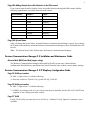
Page 484 Adding Remote Accessible Networks to the IPSec tunnel
If you want to send all traffic from the Local Accessible Networks through the IPSec tunnel, add the
following eight Remote Accessible Networks to the tunnel.
Network Number
IP Address
IP Mask
R1
1.0.0.0
255.0.0.0
R2
2.0.0.0
254.0.0.0
R3
4.0.0.0
252.0.0.0
R4
8.0.0.0
248.0.0.0
R5
16.0.0.0
240.0.0.0
R6
32.0.0.0
224.0.0.0
R7
64.0.0.0
192.0.0.0
R8
128.0.0.0
128.0.0.0
Page 540 System Name
After you change the System Name, restart the Business Communications Manager system. If you change
the System Name and do not restart the Business Communications Manager system, Scheduled tasks will
not run.
Note: The System Name is the Netbios name of Business Communications Manager.
Business Communications Manager 2.5 Installation and Maintenance Guide
Mirrored disk (RAID) hard disk jumper settings
The Business Communications Manager Mirrored disk (RAID) system uses a Master/Master
configuration. Hard disk drives purchased from Nortel Networks come with the correct jumper settings.
Business Communications Manager 2.5 IP Telephony Configuration Guide
Page 26 VLAN port number
In Table 3, replace item 3.c with the following.
3.c Does the switch use VLANs? If so, get the 802.1Q VLAN ID.
Page 30 VLAN port number
In Table 7, replace item 7.c with the following.
7.c If DHCP is not being used, or if you want to enter the port manually, has the 802.1Q VLAN ID been
supplied, if one is being used on the switch?
Page 37 VLAN
For the VLAN field, you must select 0 (no VLAN) or 1 (Manual VLAN). Option 2 (Automatic) is not
available.
4
Page 60 Configuring codecs
The following note should be added to Step 5.
Note: If you choose the None option, there is no preferred codec for this level. This means that any codec
that is supported by Business Communications Manager can be used.
Page 94 MCDN over VoIP M1 ITG configuration updates
Make sure the Meridian 1 ITG meets the following requirements:
•
ITG 2.8.24* or 2.24.24*
•
Rls 25.30 or higher
•
S/W Packages 57, 58, 59, 145, 147, 148, 160
*A maintenance release for ITG 2.X.26 will introduce Media Card support for Meridian 1 to Business
Communications Manager.
Page 110 Adjust the jitter buffer size
The following note should be added.
Note: Business Communications Manager does not support Fax over IP calls.
Page 128 Decision: does the intranet meet IP telephony QoS needs?
The following note should be added.
Note: Business Communications Manager does not support Fax over IP calls.
Page 134 Nortel NetVision Phone Administrator (NVPA)
The NVPA application is not available on Business Communications Manager. To download NVPA, go
to the Symbol web site (http://www.symbol.com/services/downloads/nvfirmware2.html).
Remote gateway: Gateway Type and Protocol changes
If you set up IP trunks on your Business Communications Manager 2.5 system, you will need to adjust the
Remote Gateway records when you upgrade to Feature Pack 1 and newer versions.
You must now select a Gateway Type and a Gateway Protocol. These fields determine what type of system
the gateway connects to, and what protocol you are using to make that connection.
Note: The following information is contained in the Business Communications Manager 2.5 Feature
Pack 1 IP Telephony Configuration Guide.
To update the Remote Gateway:
1. In Unified Manager, open Services, IP Telephony, H.323 Trunks, and click on Remote Gateway.
The remote gateway tab appears. The Remote Gateway screen shows all gateway records that have
been added to the system.
2. Select the gateway record you want to change.
3. On the top menu, click Configuration, and select Modify entry.
The Remote Gateway window appears.
5
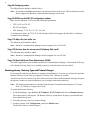
4. Use the information in the table below to choose the appropriate Gateway Type and Gateway
protocol.
Table 1 Remote gateway record
Field
Value
Description
Gateway Type
BCM2.5
BCM 2.0
ITG
Choose the type of system that is accessed through the remote gateway:
BCM2.5: Business Communications Managers running 2.5 or newer
software
BCM 2.0: Business Communications Managers running 2.0 software, or
Enterprise Edge systems running 2.0.x software.
ITG: Meridian 1 Internet Telephony Gateway
Gateway Protocol
None
SL-1
Select the gateway protocol that the trunk expects to use.
None: No special features
SL-1: MCDN protocol for gateways that provide MCDN over VoIP service
Note: You require a keycode for SL-1 protocol.
5. Click Save.
6. Repeat for all your Remote Gateway records.
Using Radvision ECS 2.1.0.1 as the gatekeeper for VoIP trunks
When you use Radvision ECS 2.1.0.1 as the gatekeeper with the Business Communications Manager VoIP
trunks, specifically with the FP1 Maintenance Release, use the configurations described in this section.
For detailed information about Radvision, and how to open and use the application, refer to the
documentation for the application.
Business Communications Manager requirements
On the Business Communications Manager Local Gateway IP interface screen:
These fields are mandatory:
• Call Signaling
• Gatekeeper IP
• Alias Names
These fields are optional:
• Registration TTL
• Gateway Protocol
Note: Refer to the IP Telephony Guide for details about using the Local Gateway IP interface screen.
Configuring the Radvision application as a Business Communications Manager gatekeeper
To ensure compatibility with the Business Communications Manager FP1 Maintenance Release software,
the following configurations must be set on the Radvision ECS 2.1.0.1 gatekeeper application, which can
be obtained through http://www.radvision.com/.
1. Open the Radvision application.
2. On the viaIP Administrator screen, select the Settings tab, then click on the Basics button.
3. Beside the Who can register field, choose Everyone.
6
4. In the left frame, click the Calls button.
Ensure the following fields are set:
Table 2 Radvision Calls screen required settings
Field
Value
Description
Accept calls
check box
Box must be checked.
Routing Mode
Direct
Setup(Q.931) (not supported)
Call Control (H.245)
Set to Direct.
Check that call is active every
check box
Leave box UNCHECKED.
Enabling this feature will result in dropped calls.
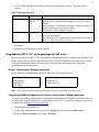
5. In the left frame click the Advanced button.
Ensure the following fields are set:
Table 3 Radvision Advanced screen required settings
Field
Value
Description
Check that the endpoint is
online every ___
check box
Leave box checked.
This setting controls the intervals when Radvision checks if the
Business Communications Manager is still on line.
Enable TTL
check box
Box must be checked.
This is the only mechanism currently supported that allows the
gatekeeper to determine if the end point (the Business
Communications Manager) is active.
Force Direct for Service Calls
check box
Check this box if you selected the Routing Mode: Direct on the
Calls screen.
Gatekeeper support for Business Communications Manager and Meridian ITG interoperability
6. Create a service configuration for ITG.
a
b
c
Select the Services tab.
Click on the Add button.
In the Prefix field, enter the unique telephone number that identifies the Meridian ITG system in
the Business Communications Manager dialing plan.
7. Define the ITG as a predefined endpoint.
a
b
Select the Endpoints tab.
Click the Add predefined button.
The Predefined Endpoint Properties dialog displays.
7
c
Ensure the following fields are set:
Table 4 Radvision Predefined Endpoints Properties settings
Field
Value
Description
Endpoint Type
Gateway
Force Online Status
check box selected
Registration IP
<ip address>
This is the IP address of the Meridian ITG system.
Aliases
Add:
Name
Phone Number
Name: The name of the ITG that will be displayed.
Phone Number: The number assigned to the ITG. Radvision
uses this number to identify calls to be routed to this ITG.
Allowed Services
Allowed
Disallowed
Ensure the ITG service is on the list, and is Allowed.
8. Close the application.
i2050 Software Phone
The i2050 Software Phone supports icons and LED indication for ringing, active and on-hold calls.
The i2050 Software Phone does not support icons and LED indications for other features and states (for
example, Call Forward, Call Center agent states, Feature 987).
CallPilot Manager Set Up and Operation Guide
The online Help for CallPilot Manager is best viewed in Internet Explorer. There can be some page format
inconsistencies if you use other browsers.
Page 27 Alternate extensions
The information about alternate extensions should be:
You can assign up to two alternate extensions to each Subscriber Mailbox. If a caller dials the main
extension (the extension that has alternate extensions assigned), the call rings at the main extension only.
Note: The exception to this is when alternate extensions are assigned an Answer DN for the main
extension. If you assign an Answer DNs, calls ring at all the extensions. Answer DNs are assigned
to extensions in system programming. For more information refer to your system documentation.
Assign alternate extensions to subscribers who need to have two or three extensions on the same system.
For example, an engineer may have a lab phone and a desk phone. When you set up the mailbox, assign
the lab phone as the alternate extension. When the engineer is in the lab they see Message Waiting
Indication when they receive a message on their primary extension, and they can log on and hear the
message in their mailbox.
Only extensions that do not have a mailbox assigned can be used as an alternate extension. There are no
default alternate extensions programmed for Subscriber mailboxes.
Alternate extensions receive the same Message Waiting Indication and Caller Display information as the
primary extension. Mailbox owners who use the Norstar Voice Mail interface can use the Open Mailbox
feature (≤·°⁄) from alternate extensions. Subscribers can use the Interrupt feature
(≤·°‡) from the alternate extension the same way as on the primary extension.
8
Page 141 Alternate extensions
The definition for alternate extensions should be:
An alternate extension gives a subscriber Message Waiting Indication on up to two other telephones that
they can access their mailbox from.
Alternate extensions are available only on Subscriber mailboxes.
About adding mailboxes
When you add a mailbox, do not create a name for the mailbox that starts with the number 1, for example
“1Smith”, “1Fax”, “1Information” or “1Calgary”.
This applies to all types of mailboxes:
•
Guest and Subscriber mailboxes
•
Information mailboxes
•
Fax Overflow and Fax On Demand mailboxes
•
Network Site and Network AMIS mailboxes.
CallPilot Desktop Messaging Quick Reference Guide
The Web Messaging feature described in this guide is not available on Business Communications
Manager.
CallPilot Message Networking Set Up and Operation Guide
Page 54 Creating a Network AMIS mailbox
The statement
•
Use the "Changing Network Delivery Mailbox Parameters" on page 57 to record the details of the
Network AMIS mailboxes you create.
should be
•
Use the "Network AMIS mailbox table" on page 69 to record the details of the Network AMIS
mailboxes you create.
CallPilot Message Networking User Guide
Page 13 To reply to a network message - Norstar Voice Mail
Step 4 should be:
4. Press MSG.
If you are replying to a message with more than one recipient, go to step 5.
If you are replying to a message with one recipient, go to step 6.
Step 8 should be:
8. Press OK to accept your recording.
If you are replying to a digital message, go to step 9.
If you are replying to an AMIS message, go to step 10.
9
The Private message option
Throughout the guide, the Private message option for the CallPilot interface is available for digital
messages only.
CallPilot Unified Messaging Installation and Maintenance Guide
Page 7 Required disk space
The document states that you need 15 Mbytes of free disk space for Unified Messaging. This is the amount
of space required for the Unified Messaging application. However, to install Unified Messaging you
require additional free disk space.
•
If you choose the option Run this program from its current location when you install Unified
Messaging, you need an additional 230 Mbytes of disk space to install (for a total of 245 Mbytes). After
the installation is complete, the temporary files are automatically deleted to recover the 230 Mbytes of
disk space.
•
If you choose the option Save this program to disk when you install Unified Messaging, you need an
additional 90 Mbytes of disk space to install (for a total of 105 Mbytes). The installation files are not
deleted by the installation wizard when you install using this option. To recover the additional
90 Mbytes of disk space, delete the installation files you down loaded from the Business
Communications Manager system.
Call Center Set Up and Operation Guide
Page 108 Setting up Routing Tables
The following information replaces the Note on this page.
Note: Overflow rules apply only after Routing Table steps are completed. If the overflow timer expires,
during a call routing step, the call will be routed after the current routing step is complete.
For example, if you want callers to overflow to another skillset after 40 seconds, you could set up a Routing
Table to:
1. Play a greeting for 10 or more seconds ("You have reached the service line of Bridgestone
Computers. Please hold and a representative will be with you shortly.")
2. Distribute (hold) the call for 20 seconds.
3. Play a second greeting of 10 or more seconds ("Your call is very important to us so please stay on
the line.")
4. Goto step 2.
In this example the call will overflow to the other skillsets you have selected after step 3.
However, if you set the Distribute For time in step 2 to 40 seconds, the call overflows after step 2 and does
not go to step 3. The actual time that the caller is waiting is 50 seconds, not 40 seconds, because the
overflow rules apply after the routing table step (step 2 in this example) is complete.
10
Multimedia Call Center Guides
Throughout the Multimedia Call Center Set Up and Operation Guide and the Multimedia Call Center Web
Developer Guide each occurrence of “Voice Button” is now “Multimedia Call Center.”
Multimedia Call Center Set Up and Operation Guide
Note: The changes appear in bold text.
Page 39 Multimedia Call Center message templates
The folder names listed in the document are incorrect. The name of the message template folders are:
•
C:\Program Files\Nortel Networks\Multimedia Call Center\html
•
C:\Program Files\Nortel Networks\Multimedia Call Center\html\adm
Multimedia Call Center Web Developer Guide
Note: The changes appear in bold text.
Page 7 Multimedia Call Center message templates
The folder names listed in the document are incorrect. The name of the message template folders are:
•
C:\Program Files\Nortel Networks\Multimedia Call Center\html
•
C:\Program Files\Nortel Networks\Multimedia Call Center\html\adm
Page 26 Multimedia Call Center CGI parameters
The statement,
•
For example, group = skillset01.
should be:
•
For example, group = skset01.
Page 28 Using a URL-encoded hypertext link interface
The line of code,
•
<A HREF="http://voicebutton.<domain>:6800/ivb-cgi-bin/vb.exe?cmd=call&skillset=1">
should be:
•
<A HREF="http://voicebutton.<domain>:6800/ivb-cgi-bin/vb.exe?cmd=call&group=skset01" TARGET="_top">
Page 28 Using voice button with HTML frames
The line of code,
•
<INPUT TYPE="hidden" NAME="skillset" VALUE="1">
should be:
•
<INPUT TYPE="hidden" NAME="group" VALUE="skset01">
11
Page 29 Communicating with Multimedia Call Center agent software
The line of code,
•
<A HREF="http://voicebutton.<domain>:6800/ivb-cgi-bin/vb.exe?cmd=call&skillset=1&monitor=on">
should be:
•
<A HREF="http://voicebutton.<domain>:6800/ivb-cgi-bin/vb.exe? cmd=call&group=skset01&monitor=on"
TARGET="_top">
Page 29 Placing a browser only call to an agent
The line of code,
•
<A HREF="http://voicebutton.<domain>:6800/ivb-cgi-bin/vb.exe?cmd=chat&skset=1">
should be:
•
<A HREF="http://voicebutton.<domain>:6800/ivb-cgi-bin/vb.exe?cmd=chat&group=skset01" TARGET="_top">
Page 30 Call preferences - the setup command
In the first example, the line of code
•
<A HREF="http://voicebutton.<domain>:6800/ivb-cgi-bin/vb.exe?cmd=setup">
should be:
•
<A HREF="http://voicebutton.<domain>:6800/ivb-cgi-bin/vb.exe?cmd=setup" TARGET="_top">
Page 30 Call preferences - the setup command
In the second example, the line of code
•
<A HREF="http://voicebutton.<domain>:6800/ivb-cgi-bin/vb.exe?cmd=call&skillset=1&do_setup=on">
should be:
•
<A HREF="http://voicebutton.<domain>:6800/ivb-cgi-bin/vb.exe?cmd=call&group=skset01&do_setup=on"
TARGET="_top">
Nortel Networks ipView Software Wallboard Set Up and Operation Guide
Page 7 Short view
This note is added to Short view:
Note that each time you start ipView the parameter values will be blank until ipView has received some
data from Nortel Networks Call Center Reporting or another ipView SoftBoard which is echoing to yours.
(For a description of echoing, see page 23.)
12
Page 24 Data Echoing IP Address List
This text is added to Data Echoing IP Address List:
Note that ipView expects the IP Addresses in the Data Echoing IP Address List to remain constant. If they
are altered then the Data Echoing IP Address List should be amended to match. This will not happen
without manual intervention on a physical Wallboard. However, if the Wallboard being echoed to is an
ipView Software wallboard running on a PC that uses DHCP to obtain its IP Address, then the IP Address
of the PC could be subject to change. DHCP enabled PCs usually receive the same IP Address each time
they re-boot. However, if the PC has been turned off for a period in excess of the IP Address lease time
for your network and the IP Address has been allocated to another PC, then it will receive a new IP
Address.
If the IP Address of a physical Wallboard or an ipView Software Wallboard changes, the Data Echoing IP
Address List must be updated to reflect the new IP Address of the Wallboard device.
Nortel Networks Call Center Reporting Set Up and Operation Guide
Page 8 Multiple installations
This note is added about multiple Business Communications Manager 2.5/CallPilot installations:
Do not install both sets of client software on a single PC. One PC on your network should be nominated
as the Master Client PC. Any other PC which will run the client software must be running the multiple
client software. No PC may be used to run both sets of software. If you have multiple Business
Communications Manager or CallPilot installations at your premises connected to a single network, then
you must have more than one Master Client, but each Master Client must be driven by a single Business
Communications Manager or CallPilot.
Page 15 Installation Prerequisites
Step 4 is added to the Installation Prerequisites:
4. The Master Client Address has been set in the Call Center Platform, and the Call Center Reporting
Software Authorization Code has been entered. (The Master Client Address is found in CallPilot
Manager under Call Center, General Properties.)
The Master Client Address is the address where the real time data stream for Call Center Reporting
purposes is delivered. You must enter either the host name or the IP address of the computer that is
running the Call Center Reporting Master Client.
The Master Client Address appears only if you use Call Center Professional on a Business
Communications Manager 2.5 system, or if you have purchased and enabled the Call Center
Reporting Software Authorization Code. Contact your service representative if you are interested in
the Call Center Reporting Software Authorization Code.
Page 22 Network name of the Master Client PC
This note is added to step 14:
You must enter the Network Name of the Master Client PC – do not enter the IP Address of the Master
Client PC. You must enter the Network Name of the Master Client PC for the Multiple Client software to
operate correctly. Enter the Network Name of the Master Client without any backslashes \\. For example,
if the Network name of the Master Client was \\MISMaster, enter it as MISMaster.
13
Page 31 Starting Call Center Reporting
This note is added to step 1:
The first time Nortel Networks Call Center Reporting is started on the Master Client it will create
Configuration Database, which is required for the RDBServer to operate correctly. Because of this, ensure
that the first time you start Nortel Networks Call Center Reporting on the Master Client you start it by
double-clicking on the Call Center Reporting icon on the desktop of the Master Client PC.
Page 43 Configuring Wallboards
This paragraph is added to the introduction:
You may assign multiple Wallboards to display information relating to any of the Skillsets or totals for the
whole Call Center system. Nortel Networks Call Center Reporting will directly address a maximum of 16
Wallboards. However, if any of the Wallboards are the ipView Software Wallboard, these can be
configured to re-transmit their received data (called ‘echoing’) to other Wallboards, which can be a
mixture of ipView Software Wallboards or hardware Wallboards. Similarly, any of these other ipView
Software Wallboards may be configured to echo to other Wallboards. In this way any number of IP
Wallboards may be driven from a single Nortel Networks Call Center Reporting application.
Page 44 IP Address
This text added to IP Address:
The Wallboard will have been assigned an IP Address when it was installed. Enter the IP Address for the
Wallboard into this field. The IP Address of each Wallboard must be unique. You must specify the IP
address of the Wallboard, not the network machine name.
Note that the MIS expects the IP Address of the Wallboard to remain constant. If it is altered then the MIS
Wallboard configuration should be amended to match. This will not happen without manual intervention
on a physical Wallboard. However, if the Wallboard is an ipView SoftBoard running on a PC that uses
DHCP to obtain its IP Address, then the IP Address of the PC could be subject to change. DHCP-enabled
PCs usually receive the same IP Address each time they re-boot.
However, if the PC has been turned off for a period in excess of the IP Address lease time for your network
and the IP Address has been allocated to another PC, then it will receive a new IP Address.
If the IP Address of a physical Wallboard or an ipView SoftBoard software wallboard changes, the MIS
Config must be updated to reflect the new IP Address of the Wallboard device.
Page 49 Wallboard Alarms
This note is added to Wallboard Alarms:
If the Alarm condition is still true following an alarm from Norstar Call Center Reporting being sent to the
wallboards, a new alarm is sent. If you have configured the alarm to send a scrolling message then you will
not be able to see the actual parameter values on the wallboard as these are cleared before the message is
scrolled. Repeated alarm messages will obscure the parameter values for the duration of their scrolling. If
this is happening on your site and you do not wish it happen then you can configure static alarms. These
are ‘blinking’ alarms without messages. Remember: if the alarm sends a wallboard message, once the
configured alarm threshold has been met, the wallboard will not display stats until the alarm condition is
no longer met and the alarm message disappears.
14
Page 84 Day of the week
Added this paragraph:
Also, note that the Day of the Week field indicates which day’s stats you wish to have printed, but the
actual printout will occur on the following day. For example, if you select Monday, the printout will occur
on Tuesday. This is to ensure that the selected day has completely elapsed and that the printed reports show
the correct and complete totals for the selected day(s).
Business Communications Manager product and documentation updates
For the latest information about Business Communications Manager product and documentation updates,
access the Nortel Networks ITAS web site at the following URL:
http://www.nortelnetworks.com/support
1-800-4 NORTEL
www.nortelnetworks.com
P0992346 Issue 02
Printed in Canada