1
BayRS Version 15.1
Part No. 308640-15.1 Rev 00
October 2001
600 Technology Park Drive
Billerica, MA 01821-4130
Configuring RADIUS
Copyright © 2001 Nortel Networks
All rights reserved. October 2001.
The information in this document is subject to change without notice. The statements, configurations, technical data,
and recommendations in this document are believed to be accurate and reliable, but are presented without express or
implied warranty. Users must take full responsibility for their applications of any products specified in this document.
The information in this document is proprietary to Nortel Networks Inc.
The software described in this document is furnished under a license agreement and may only be used in accordance
with the terms of that license. The software license agreement is included in this document.
Trademarks
Nortel Networks, the Nortel Networks logo, the Globemark, Advanced Remote Node, AN, ANH, ARN, ASN,
BayRS, BaySecure, BCC, BLN, Passport, and System 5000 are trademarks of Nortel Networks.
Adobe and Acrobat Reader are trademarks of Adobe Systems Incorporated.
Microsoft, MS, MS-DOS, Win32, Windows, and Windows NT are trademarks of Microsoft Corporation.
NetWare is a trademark of Novell, Inc.
SecurID is a trademark of RSA Security Inc.
UNIX is a trademark of X/Open Company Limited.
The asterisk after a name denotes a trademarked item.
Restricted Rights Legend
Use, duplication, or disclosure by the United States Government is subject to restrictions as set forth in subparagraph
(c)(1)(ii) of the Rights in Technical Data and Computer Software clause at DFARS 252.227-7013.
Notwithstanding any other license agreement that may pertain to, or accompany the delivery of, this computer
software, the rights of the United States Government regarding its use, reproduction, and disclosure are as set forth in
the Commercial Computer Software-Restricted Rights clause at FAR 52.227-19.
Statement of Conditions
In the interest of improving internal design, operational function, and/or reliability, Nortel Networks Inc. reserves the
right to make changes to the products described in this document without notice.
Nortel Networks Inc. does not assume any liability that may occur due to the use or application of the product(s) or
circuit layout(s) described herein.
Portions of the code in this software product may be Copyright © 1988, Regents of the University of California. All
rights reserved. Redistribution and use in source and binary forms of such portions are permitted, provided that the
above copyright notice and this paragraph are duplicated in all such forms and that any documentation, advertising
materials, and other materials related to such distribution and use acknowledge that such portions of the software were
developed by the University of California, Berkeley. The name of the University may not be used to endorse or
promote products derived from such portions of the software without specific prior written permission.
SUCH PORTIONS OF THE SOFTWARE ARE PROVIDED “AS IS” AND WITHOUT ANY EXPRESS OR
IMPLIED WARRANTIES, INCLUDING, WITHOUT LIMITATION, THE IMPLIED WARRANTIES OF
MERCHANTABILITY AND FITNESS FOR A PARTICULAR PURPOSE.
In addition, the program and information contained herein are licensed only pursuant to a license agreement that
contains restrictions on use and disclosure (that may incorporate by reference certain limitations and notices imposed
by third parties).
ii
308640-15.1 Rev 00
Nortel Networks Inc. Software License Agreement
This Software License Agreement (“License Agreement”) is between you, the end-user (“Customer”) and Nortel
Networks Corporation and its subsidiaries and affiliates (“Nortel Networks”). PLEASE READ THE FOLLOWING
CAREFULLY. YOU MUST ACCEPT THESE LICENSE TERMS IN ORDER TO DOWNLOAD AND/OR USE
THE SOFTWARE. USE OF THE SOFTWARE CONSTITUTES YOUR ACCEPTANCE OF THIS LICENSE
AGREEMENT. If you do not accept these terms and conditions, return the Software, unused and in the original
shipping container, within 30 days of purchase to obtain a credit for the full purchase price.
“Software” is owned or licensed by Nortel Networks, its parent or one of its subsidiaries or affiliates, and is
copyrighted and licensed, not sold. Software consists of machine-readable instructions, its components, data,
audio-visual content (such as images, text, recordings or pictures) and related licensed materials including all whole or
partial copies. Nortel Networks grants you a license to use the Software only in the country where you acquired the
Software. You obtain no rights other than those granted to you under this License Agreement. You are responsible for
the selection of the Software and for the installation of, use of, and results obtained from the Software.
1. Licensed Use of Software. Nortel Networks grants Customer a nonexclusive license to use a copy of the
Software on only one machine at any one time or to the extent of the activation or authorized usage level, whichever is
applicable. To the extent Software is furnished for use with designated hardware or Customer furnished equipment
(“CFE”), Customer is granted a nonexclusive license to use Software only on such hardware or CFE, as applicable.
Software contains trade secrets and Customer agrees to treat Software as confidential information using the same care
and discretion Customer uses with its own similar information that it does not wish to disclose, publish or disseminate.
Customer will ensure that anyone who uses the Software does so only in compliance with the terms of this Agreement.
Customer shall not a) use, copy, modify, transfer or distribute the Software except as expressly authorized; b) reverse
assemble, reverse compile, reverse engineer or otherwise translate the Software; c) create derivative works or
modifications unless expressly authorized; or d) sublicense, rent or lease the Software. Licensors of intellectual
property to Nortel Networks are beneficiaries of this provision. Upon termination or breach of the license by
Customer or in the event designated hardware or CFE is no longer in use, Customer will promptly return the Software
to Nortel Networks or certify its destruction. Nortel Networks may audit by remote polling or other reasonable means
to determine Customer’s Software activation or usage levels. If suppliers of third party software included in Software
require Nortel Networks to include additional or different terms, Customer agrees to abide by such terms provided by
Nortel Networks with respect to such third party software.
2. Warranty. Except as may be otherwise expressly agreed to in writing between Nortel Networks and Customer,
Software is provided “AS IS” without any warranties (conditions) of any kind. NORTEL NETWORKS DISCLAIMS
ALL WARRANTIES (CONDITIONS) FOR THE SOFTWARE, EITHER EXPRESS OR IMPLIED, INCLUDING,
BUT NOT LIMITED TO THE IMPLIED WARRANTIES OF MERCHANTABILITY AND FITNESS FOR A
PARTICULAR PURPOSE AND ANY WARRANTY OF NON-INFRINGEMENT. Nortel Networks is not obligated
to provide support of any kind for the Software. Some jurisdictions do not allow exclusion of implied warranties, and,
in such event, the above exclusions may not apply.
3. Limitation of Remedies. IN NO EVENT SHALL NORTEL NETWORKS OR ITS AGENTS OR SUPPLIERS
BE LIABLE FOR ANY OF THE FOLLOWING: a) DAMAGES BASED ON ANY THIRD PARTY CLAIM; b)
LOSS OF, OR DAMAGE TO, CUSTOMER’S RECORDS, FILES OR DATA; OR c) DIRECT, INDIRECT,
SPECIAL, INCIDENTAL, PUNITIVE, OR CONSEQUENTIAL DAMAGES (INCLUDING LOST PROFITS OR
SAVINGS), WHETHER IN CONTRACT, TORT OR OTHERWISE (INCLUDING NEGLIGENCE) ARISING OUT
OF YOUR USE OF THE SOFTWARE, EVEN IF NORTEL NETWORKS, ITS AGENTS OR SUPPLIERS HAVE
BEEN ADVISED OF THEIR POSSIBILITY. The forgoing limitations of remedies also apply to any developer and/or
supplier of the Software. Such developer and/or supplier is an intended beneficiary of this Section. Some jurisdictions
do not allow these limitations or exclusions and, in such event, they may not apply.
308640-15.1 Rev 00
iii
4.
iv
General
a.
If Customer is the United States Government, the following paragraph shall apply: All Nortel Networks
Software available under this License Agreement is commercial computer software and commercial
computer software documentation and, in the event Software is licensed for or on behalf of the United States
Government, the respective rights to the software and software documentation are governed by Nortel
Networks standard commercial license in accordance with U.S. Federal Regulations at 48 C.F.R. Sections
12.212 (for non-DoD entities) and 48 C.F.R. 227.7202 (for DoD entities).
b.
Customer may terminate the license at any time. Nortel Networks may terminate the license if Customer
fails to comply with the terms and conditions of this license. In either event, upon termination, Customer
must either return the Software to Nortel Networks or certify its destruction.
c.
Customer is responsible for payment of any taxes, including personal property taxes, resulting from
Customer’s use of the Software. Customer agrees to comply with all applicable laws including all applicable
export and import laws and regulations.
d.
Neither party may bring an action, regardless of form, more than two years after the cause of the action
arose.
e.
The terms and conditions of this License Agreement form the complete and exclusive agreement between
Customer and Nortel Networks.
f.
This License Agreement is governed by the laws of the country in which Customer acquires the Software. If
the Software is acquired in the United States, then this License Agreement is governed by the laws of the
state of New York.
308640-15.1 Rev 00
Contents
Preface
Before You Begin .............................................................................................................. xi
Text Conventions ..............................................................................................................xii
Acronyms .........................................................................................................................xiv
Hard-Copy Technical Manuals ......................................................................................... xv
How to Get Help .............................................................................................................. xv
Chapter 1
RADIUS Overview
How RADIUS Works .......................................................................................................1-2
Configuring RADIUS .......................................................................................................1-4
Nortel Networks RADIUS Implementation ......................................................................1-5
RADIUS Authentication ..................................................................................................1-6
Using SecurID for Radius Authentication .................................................................1-6
Using RADIUS with Multilevel Access to the Router ................................................1-7
Using IP and IPX Unnumbered Protocols for PPP Connections ..............................1-8
Using RADIUS with a Dial Service ...........................................................................1-8
Configuring Vendor-Specific Attributes (VSAs) for Authentication ...........................1-9
Using RADIUS with Demand Circuit Groups (Site Manager only) ...........................1-9
Configuring the Remote User to Work with the RADIUS Client .............................1-10
Using RADIUS with IP Utilities ...............................................................................1-10
RADIUS Accounting .....................................................................................................1-11
Using IP and IPX Unnumbered Protocols for PPP Connections ............................1-12
Using Dial VPN Services with Multilink PPP Accounting .......................................1-12
Using RADIUS with a Dial Service .........................................................................1-13
Using RADIUS with Demand Circuit Groups (Site Manager only) .........................1-13
Using RADIUS-Compatible Servers with the RADIUS Client .......................................1-13
308640-15.1 Rev 00
v
Accepting a Remote User’s IP Address ........................................................................1-14
Configuring a RADIUS Client .......................................................................................1-14
For More Information ....................................................................................................1-15
Chapter 2
Starting RADIUS
Before You Begin ............................................................................................................2-2
Starting Configuration Tools ...........................................................................................2-2
Enabling RADIUS ...........................................................................................................2-3
Configuring Multiple RADIUS Clients .............................................................................2-8
Chapter 3
Customizing the RADIUS Client Configuration
Modifying the Client’s IP Address ...................................................................................3-1
Modifying the Authentication and Accounting Services .................................................3-3
Modifying the Protocol for RADIUS Authentication .........................................................3-5
Modifying Router Access ................................................................................................3-6
Modifying the PPP Authentication Protocol ....................................................................3-7
Removing RADIUS Authentication and Accounting .......................................................3-8
Setting the Debug Message Level ..................................................................................3-9
Chapter 4
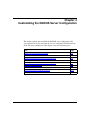
Customizing the RADIUS Server Configuration
Modifying the Primary Server’s Password ......................................................................4-2
Modifying the Server Mode .............................................................................................4-3
Designating Authentication and Accounting UDP Ports .................................................4-4
Modifying the Server Response Time ............................................................................4-6
Modifying the Number of Client Requests to the Server ................................................4-7
Configuring Alternate Servers ........................................................................................4-9
Reconnecting to the Primary Server ............................................................................4-11
Changing the Primary and Alternate Servers ...............................................................4-12
Removing a Server Entry .............................................................................................4-14
Appendix A
Site Manager Parameters
Client IP Address Parameter ......................................................................................... A-2
Server Configuration Parameters .................................................................................. A-3
Protocol Parameters for RADIUS Authentication ........................................................... A-7
vi
308640-15.1 Rev 00
Appendix B
Monitoring RADIUS Using the
BCC show Commands
Online Help for show Commands .................................................................................. B-2
show radius alerts .......................................................................................................... B-3
show radius clients ........................................................................................................ B-4
show radius servers general .......................................................................................... B-5
show radius servers timers ............................................................................................ B-6
show radius stats accounting ......................................................................................... B-7
show radius stats authentication .................................................................................... B-8
Appendix C
Configuration Examples
Configuring RADIUS Authentication .............................................................................. C-2
Configuring RADIUS Accounting ................................................................................... C-6
Configuring RADIUS Accounting and Authentication .................................................. C-12
Appendix D
Vendor-Specific Attributes
Nortel Networks Vendor-Specific Attributes ................................................................... D-2
RADIUS Dictionary File ................................................................................................. D-3
Appendix E
Configuring RADIUS with SecurID
Configuring RADIUS Client and ACE/Server Attributes
on the Router ................................................................................................................. E-2
Configure a RADIUS Client .............................................................................. E-5
Configure a RADIUS Server ............................................................................. E-6
Select a Protocol for RADIUS Authentication .................................................. E-7
Configuring the ACE/Server .......................................................................................... E-8
Establishing User Authentication ................................................................................... E-8
Logging In the First Time Using “New PIN” Mode ................................................... E-9
Logging In with a Valid PIN ................................................................................... E-10
“Next Tokencode” Prompt ...................................................................................... E-10
Index
308640-15.1 Rev 00
vii
Figures
Figure 1-1.
Sample Network Using RADIUS ..............................................................1-3
Figure 2-1.
BCC Hierarchy of Objects ........................................................................2-3
Figure 2-2.
Configuration Manager Window ...............................................................2-3
Figure A-1.
RADIUS Client Configuration Window .................................................... A-2
Figure A-2.
RADIUS Server Configuration Window ................................................... A-3
Figure A-3.
RADIUS Dial_In Protocol Window .......................................................... A-7
Figure C-1.
Sample Network Using RADIUS Authentication ..................................... C-2
Figure C-2.
Sample Network Using RADIUS Accounting .......................................... C-6
Figure C-3.
Sample Network Configured for Dialing an Alternate Site .................... C-12
308640-15.1 Rev 00
ix
Preface
This guide describes Remote Authentication Dial-In User Service (RADIUS) and
what you do to start and customize RADIUS services on a Nortel Networks*
router.
You can use the Bay Command Console (BCC*) or Site Manager to configure
RADIUS on a router. In this guide, you will find instructions for using both the
BCC and Site Manager.
Before You Begin
Before using this guide, you must complete the following procedures. For a new
router:
•
Install the router (see the installation guide that came with your router).
•
Connect the router to the network and create a pilot configuration file (see
Quick-Starting Routers, Configuring Remote Access for AN and Passport
ARN Routers, or Connecting ASN Routers to a Network).
Make sure that you are running the latest version of Nortel Networks BayRS* and
Site Manager software. For information about upgrading BayRS and Site
Manager, see the upgrading guide for your version of BayRS.
308640-15.1 Rev 00
xi
Configuring RADIUS
Text Conventions
This guide uses the following text conventions:
angle brackets (< >)
Indicate that you choose the text to enter based on the
description inside the brackets. Do not type the
brackets when entering the command.
Example: If the command syntax is:
ping <ip_address>, you enter:
ping 192.32.10.12
bold text
Indicates command names and options and text that
you need to enter.
Example: Enter show ip {alerts | routes}.
Example: Use the dinfo command.
braces ({})
Indicate required elements in syntax descriptions
where there is more than one option. You must choose
only one of the options. Do not type the braces when
entering the command.
Example: If the command syntax is:
show ip {alerts | routes}, you must enter either:
show ip alerts or show ip routes, but not both.
brackets ([ ])
Indicate optional elements in syntax descriptions. Do
not type the brackets when entering the command.
Example: If the command syntax is:
show ip interfaces [-alerts], you can enter either:
show ip interfaces or show ip interfaces -alerts.
ellipsis points (. . . )
Indicate that you repeat the last element of the
command as needed.
Example: If the command syntax is:
ethernet/2/1 [<parameter> <value>] . . . , you enter
ethernet/2/1 and as many parameter-value pairs as
needed.
xii
308640-15.1 Rev 00
Preface
italic text
Indicates new terms, book titles, and variables in
command syntax descriptions. Where a variable is two
or more words, the words are connected by an
underscore.
Example: If the command syntax is:
show at <valid_route>
valid_route is one variable and you substitute one value
for it.
screen text
Indicates system output, for example, prompts and
system messages.
Example: Set Trap Monitor Filters
separator ( > )
Shows menu paths.
Example: Protocols > IP identifies the IP option on the
Protocols menu.
vertical line ( | )
Separates choices for command keywords and
arguments. Enter only one of the choices. Do not type
the vertical line when entering the command.
Example: If the command syntax is:
show ip {alerts | routes}, you enter either:
show ip alerts or show ip routes, but not both.
308640-15.1 Rev 00
xiii
Configuring RADIUS
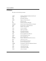
Acronyms
This guide uses the following acronyms:
xiv
CHAP
Challenge Handshake Authentication Protocol
DVS
Dial VPN Services
FTP
File Transfer Protocol
HTTP
Hypertext Transfer Protocol
IP
Internet Protocol
IPX
Internetwork Protocol Exchange
IPXWAN
Internet Packet Exchange Wide Area Network
ISDN
Integrated Services Digital Network
ISP
Internet service provider
LAN
local area network
LCD
liquid crystal display
NTP
Network Time Protocol
OSPF
Open Shortest Path First
PAP
Password Authentication Protocol
POTS
Plain Old Telephone Service
PPP
Point-to-Point Protocol
RADIUS
Remote Authentication Dial-In User Service
RAS
remote access server
RIP
Routing Information Protocol
SAP
Service Advertising Protocol
TCP/IP
Transmission Control Protocol/Internet Protocol
UDP
User Datagram Protocol
VPN
virtual private network
VSA
vendor-specific attribute
WAN
wide area network
308640-15.1 Rev 00
Preface
Hard-Copy Technical Manuals
You can print selected technical manuals and release notes free, directly from the
Internet. Go to the www.nortelnetworks.com/documentation URL. Find the
product for which you need documentation. Then locate the specific category and
model or version for your hardware or software product. Use Adobe* Acrobat
Reader* to open the manuals and release notes, search for the sections you need,
and print them on most standard printers. Go to Adobe Systems at the
www.adobe.com URL to download a free copy of the Adobe Acrobat Reader.
You can purchase selected documentation sets, CDs, and technical publications
through the Internet at the www1.fatbrain.com/documentation/nortel/ URL.
How to Get Help
If you purchased a service contract for your Nortel Networks product from a
distributor or authorized reseller, contact the technical support staff for that
distributor or reseller for assistance.
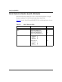
If you purchased a Nortel Networks service program, contact one of the following
Nortel Networks Technical Solutions Centers:
Technical Solutions Center
Telephone
Europe, Middle East, and Africa
(33) (4) 92-966-968
North America
(800) 4NORTEL or (800) 466-7835
Asia Pacific
(61) (2) 9927-8800
China
(800) 810-5000
Additional information about the Nortel Networks Technical Solutions Centers is
available from the www.nortelnetworks.com/help/contact/global URL.
An Express Routing Code (ERC) is available for many Nortel Networks products
and services. When you use an ERC, your call is routed to a technical support
person who specializes in supporting that product or service. To locate an ERC for
your product or service, go to the http://www130.nortelnetworks.com/cgi-bin/
eserv/common/essContactUs.jsp URL.
308640-15.1 Rev 00
xv
Chapter 1
RADIUS Overview
RADIUS (Remote Authentication Dial-In User Service) enables Internet service
providers (ISPs) to offer more remote access services to their customers. Remote
access is one of the fastest growing segments of the networking industry. Users in
branch offices, sales people in the field, and telecommuters are just a few of the
people who rely on remote access to do their jobs.
This chapter provides a conceptual overview of RADIUS, and explains how
Nortel Networks implements it. This chapter covers the following topics:
Topic
Page
How RADIUS Works
1-2
Configuring RADIUS
1-4
Nortel Networks RADIUS Implementation
1-5
RADIUS Authentication
1-6
RADIUS Accounting
1-11
Using RADIUS-Compatible Servers with the RADIUS Client
1-13
Accepting a Remote User’s IP Address
1-14
Configuring a RADIUS Client
1-14
For More Information
1-15
308640-15.1 Rev 00
1-1
Configuring RADIUS
How RADIUS Works
As networks grow to accommodate more users, network security and billing
become more difficult to manage. RADIUS centralizes security and controls
billing services. RADIUS thus not only improves security but also adapts to the
ever-increasing volume and needs of remote users and service providers.
A RADIUS application has two components, the RADIUS server and the
RADIUS client.
The RADIUS server is a computer equipped with server software (for example, a
UNIX* workstation) that is located at a central office or campus. It has
authentication and access information in a form that is compatible with the client.
A network can have one server for both authentication and accounting, or one
server for each service.
The RADIUS client can be a router or a remote access server that is equipped with
client software and that typically resides on the same local area network (LAN)
segment as the server. The client is the network access point between the remote
users and the server.
RADIUS authentication lets you identify remote users before you give them
access to a central network site. RADIUS accounting enables the server to collect
data during a remote user’s dial-in session with the client. The server can then
determine billing charges.
1-2
308640-15.1 Rev 00
RADIUS Overview
M
O
DE
M
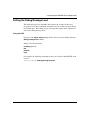
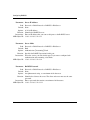
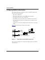
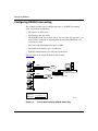
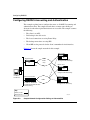
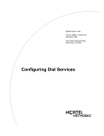
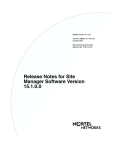
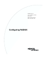
Figure 1-1 shows a sample network using RADIUS over a POTS (Plain Old
Telephone Service) line and an ISDN (Integrated Services Digital Network).
POTS
Remote dial-in
user
BLN
ISDN
RADIUS
server
RADIUS client
Remote dial-in
user
CR0001A
Figure 1-1.
308640-15.1 Rev 00
Sample Network Using RADIUS
1-3
Configuring RADIUS
Configuring RADIUS
To configure the RADIUS server and client, follow these steps:
1.
•
For Nortel Networks servers, copy the bayrs.dct, vendor.ini, and
dictiona.dcm files from the distribution CD to the directory you define at
installation time (usually C:\RADIUS\Services). For more information,
see Appendix D, “Vendor-Specific Attributes” and the BaySecure Access
Control Administration Guide for your platform (UNIX, NetWare*, or
Microsoft* Windows NT*).
•
For non-Nortel Network servers, use the bayrs.dct file shown in
Appendix D to modify your existing RADIUS dictionary. Because the
bayrs.dct file is in the format of some popular RADIUS servers, you may
be able to use it as a direct replacement for the existing RADIUS
dictionary. For more information, refer to the vendor-specific server
documentation.
2.
Configure the user-specific information in the RADIUS server database. For
more information, refer to the vendor-specific documentation.
3.
Configure the BayRS RADIUS client using either Site Manager or the BCC.
For more information, see Chapters 2 through 4.
4.
1-4
Install the RADIUS server files. These files load at server startup and enable
the server to recognize the vendor-specific RADIUS clients.
a.
Define the RADIUS slots and services to be provided (authentication,
accounting, or both).
b.
Configure the primary and secondary RADIUS servers.
Configure RADIUS-enabled applications (dial services, HTTP, FTP, NTP,
Telnet).
308640-15.1 Rev 00
RADIUS Overview
Nortel Networks RADIUS Implementation
The following Nortel Networks platforms can operate as RADIUS clients:
•
Access Node (AN*)
•
Access Node Hub (ANH*)
•
Access Stack Node (ASN*)
•
Advanced Remote Node* (ARN*)
•
Backbone Concentrator Node (BCN*)
•
Backbone Link Node (BLN*)
•
System 5000*
From one central location, RADIUS enables you to administer remote user
accounts through its full range of authentication and accounting services.
The remote users include:
•
Routers with customized user profiles and routers from other vendors.
(RADIUS supports these routers by using vendor-specific attributes.)
•
System administrators who log onto the RADIUS client from a local console
or Telnet.
•
Routers that act as dial-up servers (concentrators).
•
Other services that the server can authenticate such as FTP and HTTP.
Note: To configure RADIUS with any service other than demand circuit
groups, Nortel Networks recommends using the BCC.
RADIUS supports unnumbered IP addresses (demand circuit groups) and
numbered IP addresses (dial-up services). RADIUS clients that use dial-up
services typically use demand circuits, but they can also use backup or bandwidth
circuits.
To enable RADIUS, you must specify the client’s Internet Protocol (IP) address.
As the RADIUS client, the router passes this address to the server when a remote
user makes an authentication or accounting request. The server will not accept the
request without the client’s IP address.
308640-15.1 Rev 00
1-5
Configuring RADIUS
The client can also support a primary server, which is the original destination
server, and an alternate server, which is a server that the client contacts if it
cannot reach the primary server.
RADIUS Authentication
You configure RADIUS authentication on a slot-by-slot basis. Therefore, a call
designated for a RADIUS-configured slot can perform authentication. You can
also configure a slot for authentication even if the router is already using that slot
for a dial-up service. This includes dial-up services for both:
•
Unnumbered IP addresses (demand circuit groups). For more information, see
“Using IP and IPX Unnumbered Protocols for PPP Connections” on page 1-8.
•
Numbered IP addresses (dial-on-demand, dial backup, and
bandwidth-on-demand). For more information, see “Using RADIUS with a
Dial Service” on page 1-8.
When a remote user calls the RADIUS client, the client passes the call request,
referred to as the access challenge, to the RADIUS server. The access challenge
contains the user’s name and password. The server verifies the user’s identity and,
for authorized callers, responds with an access accept message, which includes
the required access information. This information is sent to the client, which
passes it to the remote user. If the remote user is not authorized, the server
responds with an access reject message.
The client can pass multiple requests to the server simultaneously. If the client
cannot reach the server, and you configured an alternate server, the client passes
the request to the alternate server.
The authentication process occurs only once for each call. Once RADIUS
authentication is complete, the remote user can communicate with the destination
network.
Using SecurID for Radius Authentication
For the highest level of protection from unauthorized users, you can use SecurID*
for RADIUS authentication. Nortel Networks implements SecurID on ARN
routers, which operate as RADIUS clients.
1-6
308640-15.1 Rev 00
RADIUS Overview
SecurID, a token-passing security feature developed by Security Dynamics, Inc.,
prohibits unauthorized users from accessing a RADIUS client through a router
management application (Telnet, HTTP, FTP, or the Technician Interface). A
RADIUS client configured with SecurID communicates with a centrally located
ACE/Server to identify and authenticate authorized users.
SecurID offers a more advanced level of authentication because it requires two
security checks instead of one. To access the protected router, you must enter a
valid SecurID PASSCODE, which consists of:
•
A secret, memorized personal identification number (PIN)
•
The current token code, generated by your assigned SecurID card. The token
code appears in the liquid crystal display (LCD) of the SecurID card. The
code changes at a specified interval, typically 60 seconds.
The combination of the PIN and the token code ensures exceptionally secure user
authentication and access control.
Each user authorized to access a RADIUS client configured with SecurID must
have an electronic SecurID card issued by Security Dynamics, Inc. Security
Dynamics programs each card with a PIN to uniquely identify its prospective
owner, and then assigns the card for exclusive use to that person only.
Using RADIUS with Multilevel Access to the Router
System administrators and network operators can use RADIUS authentication
services from a console connected to the router. This feature, which is part of
Nortel Networks multilevel access, grants authenticated users access to the router
for configuration and monitoring purposes. Nortel Networks recommends that
you use the BCC to configure multilevel access.
Multilevel access also assigns a privilege level that determines which system
commands the user can execute. For more information, see Appendix A in Using
the Bay Command Console (BCC).
308640-15.1 Rev 00
1-7
Configuring RADIUS
Using IP and IPX Unnumbered Protocols for PPP Connections
The RADIUS client supports IP and Internetwork Packet Exchange (IPX)
unnumbered interfaces, meaning that the circuit’s interface address is 0.0.0.0. All
remote users that dial in to the same slot on the client receive the same
unnumbered protocol configuration.
Note: Unlike the circuit’s address, the RADIUS client’s address is a numbered
address.
The unnumbered circuit interface eliminates the need for a unique circuit
configuration for each remote user in a network. Therefore, an unnumbered circuit
interface reduces the configuration effort and the number of IP addresses that you
use for a large network. The client can activate any available circuit for an
incoming call because there is no specific address assigned to the circuit.
When you configure authentication for a router slot, Site Manager automatically
configures the dial-up circuits required for the client to accept calls from the
remote user. You are responsible for configuring only the unnumbered circuit
interfaces. If you use an FTP Telnet session, this configuration is unnecessary.
In addition to configuring unnumbered circuit interfaces, we recommend that you
enable IP or IPX triggered updates for the RADIUS client. The client uses
triggered updates to provide its local area network (LAN) with routing
information from the remote router. See Configuring IP, ARP, RARP, RIP, and
OSPF Services or Configuring IPX Services for more information about triggered
updates.
Using RADIUS with a Dial Service
To use RADIUS authentication with a dial service, you must configure at least one
of the three Nortel Networks dial services: dial-on-demand, dial backup, or
bandwidth-on-demand. The dial service enables the router to activate a dial-up
connection when it receives an incoming call. For information about configuring a
dial service, see Configuring Dial Services.
1-8
308640-15.1 Rev 00
RADIUS Overview
Configuring Vendor-Specific Attributes (VSAs) for Authentication
To authenticate a remote caller, the RADIUS client must identify the router
placing the call. Identify the remote caller by configuring the caller’s Challenge
Handshake Authentication Protocol (CHAP) or Password Authentication Protocol
(PAP) name and secret, so that it maps the local circuits to the name of the remote
caller.
•
In slots not configured with RADIUS, identify the remote caller by
configuring the router’s caller resolution table. (For information about caller
resolution tables, see Configuring Dial Services.)
•
In slots configured with RADIUS and dial circuits, configure the
vendor-specific attributes (VSAs) on the RADIUS server. The required VSA
is Bay-Local-IP-Address, which specifies the IP address of the local port.
This VSA must match the IP address of the interface receiving the call.
Note: Do not configure a caller resolution table if you plan to use
vendor-specific attributes.
When a call comes in that needs authentication, the RADIUS client first checks
the router’s caller resolution table for an entry that identifies the caller.
•
If the caller is authorized, the local router maps the caller to a local circuit,
and then activates that circuit.
•
If that fails, and RADIUS is configured, the client sends the RADIUS server a
request for authentication.
Using RADIUS with Demand Circuit Groups (Site Manager only)
When configuring a RADIUS client using Site Manager, Site Manager
automatically configures a demand circuit group. You will need, however, to
configure a protocol for the demand circuit group. See “Select a Protocol for
RADIUS Authentication” on page 2-7.
To identify the remote user to the RADIUS server, the remote user uses the PPP
CHAP or PAP. The client includes the remote user’s CHAP name and secret or
PAP ID and password in the access challenge to the server. You cannot use VSAs
with demand circuit groups.
308640-15.1 Rev 00
1-9
Configuring RADIUS
Configuring the Remote User to Work with the RADIUS Client
In most RADIUS networks, the remote user is a router. To enable the remote
router to work with the RADIUS authentication client, follow these guidelines:
•
Enable dial-optimized routing.
The remote router sends routing updates to advertise its LAN to the client. By
enabling dial-optimized routing, you reduce the frequency of routing updates,
preventing the line from remaining active unnecessarily.
•
Configure one-way PPP authentication.
The remote router must support one-way PPP authentication, meaning that
only the client sends CHAP challenges or PAP authentication requests to the
remote user. The remote user only recognizes and responds to the CHAP
challenges or PAP authentication requests from the client.
•
Configure a default route in the routing table of the remote router.
The client does not advertise its LAN to the remote router. To specify the path
from the remote router to the client, you configure a default route, which is a
static route that enables the remote router to contact the client.
See Appendix C for configuration examples.
Using RADIUS with IP Utilities
To use RADIUS authentication with an IP utility, you must configure the
RADIUS server so that it can recognize vendor-specific RADIUS clients.
Note: To use RADIUS with IP utilities such as FTP, NTP, HTTP, and Telnet,
your RADIUS server must support VSAs.
•
1-10
For Nortel Networks servers, copy the bayrs.dct, vendor.ini, and dictiona.dcm
files from the distribution CD to the directory you define at installation time
(usually C:\RADIUS\Services). For more information, see Appendix D,
“Vendor-Specific Attributes” and the BaySecure Access Control
Administration Guide for your platform (UNIX, NetWare, or NT).
308640-15.1 Rev 00
RADIUS Overview
•
For non-Nortel servers, use the bayrs.dct file shown in Appendix D to modify
your existing RADIUS dictionary. Because the bayrs.dct file is in the format
of some popular RADIUS servers, you may be able to use it as a direct
replacement for the existing RADIUS dictionary. For more information, refer
to the vendor-specific server documentation.
The Nortel Networks vendor ID is 1584, as allocated by the Internet Assigned
Numbers Authority. Use this ID in the VSA header.
For information on IP utilities, see Configuring IP Utilities.
RADIUS Accounting
You configure RADIUS accounting on a slot-by-slot basis. Therefore, a call
designated for a RADIUS-configured slot performs RADIUS accounting.
The RADIUS accounting server calculates billing charges for a communication
session between the remote user and the client. The RADIUS client sends
information to the server, such as the status of each call and the number of packets
transmitted during the session. Using this data, the server determines billing
charges, which the network administrator can use to manage network costs.
An accounting session is the time during which the remote user communicates
with the client. The session begins when the client passes an accounting request
from the remote user to the server, with an accounting status byte set to start. The
session ends when the client sends a second request with the accounting status
byte set to stop. Multiple accounting sessions can occur simultaneously if there
are multiple dial-up connections.
The client sends accounting requests only to the server configured for accounting,
enabling you to use different servers for accounting and authentication.
If the client cannot reach the primary server after several attempts, and you
configured an alternate server, the client sends the accounting request to the
alternate server. If an accounting session starts with the primary server, and this
server goes down, the session is continued with the alternate server. Unless the
primary server recovers, the request to end the session is then sent to the alternate
server. To accurately determine billing charges, the network administrator collects
information from all accounting servers.
308640-15.1 Rev 00
1-11
Configuring RADIUS
Using IP and IPX Unnumbered Protocols for PPP Connections
The RADIUS client supports IP and IPX unnumbered interfaces, meaning that the
circuit’s interface address is 0.0.0.0. All remote users that dial in to the same slot
on the client receive the same unnumbered protocol configuration.
Note: Unlike the circuit’s address, the RADIUS client’s address is a numbered
address.
The unnumbered circuit interface eliminates the need for a unique circuit
configuration for each remote user in a network. Therefore, an unnumbered circuit
interface reduces the configuration effort and the number of IP addresses that you
use for a large network. The client can activate any available circuit for an
incoming call because there is no specific address assigned to the circuit.
When you configure accounting for a router slot, Site Manager automatically
configures the dial-up circuits required for the client to accept calls from the
remote user. You are responsible for configuring only the unnumbered circuit
interfaces. If you use an FTP Telnet session, this configuration is unnecessary.
In addition to configuring unnumbered circuit interfaces, we recommend that you
enable IP or IPX triggered updates for the RADIUS client. The client uses
triggered updates to provide its local area network (LAN) with routing
information from the remote router. See Configuring IP, ARP, RARP, RIP, and
OSPF Services or Configuring IPX Services for more information about triggered
updates.
Using Dial VPN Services with Multilink PPP Accounting
The Dial VPN Services (DVS) feature reports multilink PPP (Point-to-Point
Protocol) usage to the RADIUS accounting server. Nortel Networks enables this
feature by default.
Prior to BayRS Version 14.00, DVS only reported one session per multilink
bundle to the RADIUS accounting server. Now, DVS reports one session per link,
so that as links are added or removed from a multilink bundle, the RADIUS
accounting server at the customer site receives accounting messages.
1-12
308640-15.1 Rev 00
RADIUS Overview
This new behavior resembles the operation of a RAS (remote access server) in
local (non-DVS) mode and allows customers to perform usage-based billing of
multilink PPP sessions.
In addition, the new multilink PPP accounting feature:
•
Does not report the Termination-Cause attribute in the accounting STOP
message.
•
Ensures uniqueness by having the gateway locally generate the NAS-Port,
Session-Id, and Multi-Session-Id attributes.
Using RADIUS with a Dial Service
To use RADIUS accounting on the router, you must configure at least one of the
three Nortel Networks dial services: dial-on-demand, dial backup, or
bandwidth-on-demand. The dial service enables the router to activate a dial-up
connection when it receives an incoming call. For information about dial services,
see Configuring Dial Services.
Using RADIUS with Demand Circuit Groups (Site Manager only)
When configuring a RADIUS client using Site Manager, Site Manager
automatically configures a demand circuit group. However, you will need to
configure a protocol for the demand circuit group. See “Select a Protocol for
RADIUS Authentication” on page 2-7.
To identify the remote user to the RADIUS server, the remote user uses the PPP
CHAP or PAP. The client includes the remote user’s CHAP name and secret or
PAP ID and password in the access challenge to the server. You cannot use VSAs
with demand circuit groups.
Using RADIUS-Compatible Servers with the RADIUS Client
The Nortel Networks RADIUS client can communicate with any
RADIUS-compatible server. You must configure the server’s IP address so that
the client can communicate with the server.
308640-15.1 Rev 00
1-13
Configuring RADIUS
To ensure that a server is always available, you can configure one primary server
and multiple alternate servers. The client tries to connect to the primary server
first. If the primary server does not respond after a certain number of attempts, the
client sends the authentication or accounting request to the alternate server. Once
the primary server recovers, the client resumes communication with the primary
server.
Accepting a Remote User’s IP Address
The client accepts the IP address of a remote user only if the remote user is a PC,
not another router. The client does not support any other RADIUS extensions.
Configuring a RADIUS Client
Nortel Networks provides a script for configuring a RADIUS client on one or
more slots in a router. With this script, you can configure all selected slots in one
operation.
Note: The RADIUS script configures each slot with the same configuration.
For information on running this script, see “Configuring Multiple RADIUS
Clients” on page 2-8.
1-14
308640-15.1 Rev 00
RADIUS Overview
For More Information
Refer to the following sources for more information about RADIUS:
Aboba, B., and G. Zorn. “RADIUS Client MIB.” Internet Draft. March 1997.
Aboba, B., and G. Zorn. “RADIUS Server MIB.” Internet Draft. March 1997.
Aboba, B., and G. Zorn. “Implementation of Mandatory Tunneling via RADIUS.”
Internet Draft. March 1997.
Internet Engineering Task Force World Wide Web site: http://ftp.ietf.org/.
Rigney, C. “RADIUS Accounting.” RFC 2139. April 1997.
Rigney, C., A. Rubens, W.A. Simpson, and S. Willens. “Remote Authentication
Dial In User Service (RADIUS).” RFC 2138. April 1997.
Rigney, C., and W. Willats. “RADIUS Extensions.” Internet Draft. January 1997.
Zorn, G. “RADIUS Attributes for Tunnel Protocol Support.” Internet Draft.
March 1997.
Zorn, G. “Extensible RADIUS Attributes for Tunnel Protocol Support.”
Internet Draft. March 1997.
308640-15.1 Rev 00
1-15
Chapter 2
Starting RADIUS
The Remote Authentication Dial-In User Service (RADIUS) centralizes
authentication and accounting information for a variety of network services such
as FTP and HTTP. By placing authentication and accounting functions in one
central location, you can improve the security and management of large networks.
In a network using RADIUS, the router is the RADIUS client. The client is the
connection point between remote users and a RADIUS server. The server has the
information that it needs to identify remote users and to keep accounting
information for each call.
This section explains how to start RADIUS using the default values for all
parameters. To customize the RADIUS configuration by modifying the default
values, see Chapters 3 and 4.
Note: If you are using SecurID for RADIUS, do not use the information in
this chapter, or in Chapters 3 and 4. Instead, see Appendix E for information
about how to start and customize RADIUS, and establish user authentication
using the BCC or Site Manager.
This chapter covers the following topics:
Topic
Page
Before You Begin
2-2
Starting Configuration Tools
2-2
Enabling RADIUS
2-3
Configuring Multiple RADIUS Clients
2-8
308640-15.1 Rev 00
2-1
Configuring RADIUS
Before You Begin
Before you enable RADIUS, do the following:
1.
Create and save a configuration file that has at least one wide area network
(WAN) interface.
2.
In Site Manager, retrieve the configuration file in local, remote, or dynamic
mode.
3.
Specify the router hardware if this is a local-mode configuration.
4.
Configure the physical interface for any ISDN lines that you will use for
RADIUS.
See Configuring Dial Services to learn how to configure ISDN lines.
5.
Configure one or more dial services so that the RADIUS client can accept
calls from remote users.
Configure dial-on-demand, dial backup, or bandwidth-on-demand service to
operate with RADIUS. See Configuring Dial Services for instructions. Once
you enable RADIUS, the RADIUS client automatically configures a dial
connection; therefore, you are not required to configure a dial service.
6.
Enable dial-optimized routing on the remote routers (RADIUS authentication
only).
Dial-optimized routing prevents Routing Information Protocol (RIP) updates
or Service Advertising Protocol (SAP) updates from keeping a line active
unnecessarily, thereby reducing the line costs. Enabling this feature improves
the operation of RADIUS authentication.
Starting Configuration Tools
Before configuring RADIUS, see the following user guides for instructions on
how to start and use the Nortel Networks configuration tool of your choice.
2-2
Configuration Tool
User Guide
Bay Command Console (BCC)
Using the Bay Command Console (BCC)
Site Manager
Configuring and Managing Routers with
Site Manager
308640-15.1 Rev 00
Starting RADIUS
Enabling RADIUS
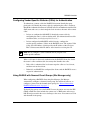
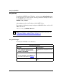
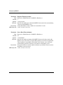
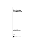
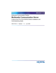
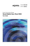
You can use the BCC or Site Manager to enable RADIUS on the router. To help
you visualize the configuration method for each interface, see the following
figures: Figure 2-1 illustrates the BCC hierarchy, and Figure 2-2 shows the Site
Manager configuration menus.
box/stack
radius
radius-client
radius-server
BCC0026A
Figure 2-1.
BCC Hierarchy of Objects
Figure 2-2.
Configuration Manager Window
308640-15.1 Rev 00
2-3
Configuring RADIUS
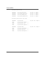
Using the BCC
To enable RADIUS and configure the IP addresses for a RADIUS client and
server:
1.
Start configuration mode by entering:
bcc> config
2.
Configure RADIUS on the box.
box# radius
3.
Configure a slot and address for the RADIUS client.
radius# radius-client slot <slot_number> address <client_address>
slot_number specifies the router slot you want to configure for RADIUS.
client_address specifies the IP address of the RADIUS client.
For example, the following command configures the RADIUS client on slot
3, at the IP address 192.32.1.1, and with default values for all the optional
parameters:
radius# radius-client slot 3 address 192.32.1.1
Note: By default, the accounting and authentication services are disabled. To
effectively use RADIUS, see page 3-3 and enable one of these services.
To configure the same RADIUS configuration on one or more slots, see
“Configuring Multiple RADIUS Clients” on page 2-8.
4.
Navigate to the top-level RADIUS prompt.
radius-client/3# back
5.
Configure an address for the RADIUS server.
radius# radius-server address <server_address>
server_address specifies the IP address of the RADIUS server.
For example, the following command configures the RADIUS server for both
accounting and authentication at the IP address 192.32.10.1:
radius# radius-server address 192.32.10.1
The above command changes the prompt to the following:
radius-server/192.32.10.1#
2-4
308640-15.1 Rev 00
Starting RADIUS
Using Site Manager
Use the steps in the following sections to enable RADIUS on a router slot and
configure the RADIUS client and server.
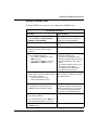
Configure a RADIUS Client
To enable RADIUS on a router slot and configure the RADIUS client:
Site Manager Procedure
You do this
System responds
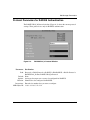
1. In the Configuration Manager window,
select Protocols > Global Protocols >
RADIUS > Create RADIUS.
The RADIUS Client Configuration window
opens, which shows the router slots
available for configuring RADIUS.
2. Click on one of the boxes labeled None.
A menu opens showing the RADIUS
options.
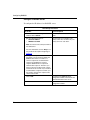
3. Select one of the RADIUS options:
• Authentication
• Accounting
• Both (to enable both services)
Your selection replaces the label None.
4. To configure this slot just for accounting,
skip to step 6.
Depending on the connector you select,
the following window opens:
• For ports on an Octal Sync Link
Module of a BLN or BCN, the Choose
WAN Serial Interface Type window
opens.
• For all other modules, the Sync Line
Media Type window opens.
• For ISDN lines, the ISDN Switch
Configuration window opens.
Otherwise, select the connectors that you
want to serve as RADIUS interfaces.
• To configure a modem line, select a
COM connector.
• To configure an ISDN line, select an
ISDN, MCTI, or MCEI connector.
5. If the Choose WAN Serial Interface Type Depending on what type you selected,
window opens, select the appropriate type either the Sync or the Async Line Media
for your dial connection:
Type window opens.
• Sync for Synchronous PPP
• Async for Asynchronous PPP
(continued)
308640-15.1 Rev 00
2-5
Configuring RADIUS
Site Manager Procedure (continued)
You do this
System responds
6. Click on OK to accept the default settings
for all windows until you return to the
RADIUS Client Configuration window.
You return to the RADIUS Client
Configuration window. Notice the letters
DR next to the names of the connectors
you configured. This indicates that the
connector is now a RADIUS interface.
7. Set the Client IP Address parameter.
For more information, click on Help or see
the parameter description on page A-2.
8. Continue to the next section to configure a
RADIUS server.
Configure a RADIUS Server
To configure the IP address for a RADIUS server:
Site Manager Procedure
You do this
System responds
1. In the RADIUS Client Configuration
window, click on Server.
The Primary Server Address window
opens.
2. Set the following parameters:
• Server IP Address
• RADIUS Password
The first server you configure is the
primary server. You can have only one
primary server for each client.
For more information, click on Help or see
the parameter descriptions beginning on
page A-3.
2-6
3. Click on OK.
You return to the RADIUS Server
Configuration window, which shows the
parameter defaults for the server.
4. Click on Done.
You return to the RADIUS Client
Configuration window.
308640-15.1 Rev 00
Starting RADIUS
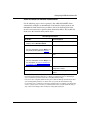
Select a Protocol for RADIUS Authentication
Use the following steps to select a protocol, after which the RADIUS client
automatically configures an unnumbered circuit interface for the protocol. An
unnumbered circuit interface has an address of 0.0.0.0, which means that the
circuit is not restricted to a specific remote destination address. This enables the
client to use the circuit for many remote users.
Site Manager Procedure
You do this
System responds
1. In the RADIUS Client Configuration
window, click on Dial-In Protocol.
The RADIUS Dial_In Slot window opens.
2. Set the Slot Number parameter.
For more information, click on Help or see
the parameter description on page A-7.
3. Click on OK.
The RADIUS Dial_In Protocol window
opens.
4. Enable the protocol you want to use.*
For more information, click on Help or see
the descriptions in “Protocol Parameters
for RADIUS Authentication” on page A-7.
5. Click on OK.
You return to the RADIUS Client
Configuration window.
6. Click on Done.
You return to the Configuration Manager
window.
* If your network uses only dial-up lines, we recommend that you enable IP together with RIP or the
Internetwork Packet Exchange (IPX) protocol. When you enable these protocols, Site Manager
opens a window that asks if the remote site is using dial-optimized routing.
If the remote site is using dial-optimized routing, click on OK. Site Manager automatically modifies
several routing update parameters so that the client can operate with dial-optimized routing.
If your network uses a combination of leased lines and dial-up lines (for example, using dial backup
service to support leased connections), it is unlikely that the routers use dial-optimized routing, so
click on Cancel. Site Manager will not modify the routing update parameters.
308640-15.1 Rev 00
2-7
Configuring RADIUS
Configuring Multiple RADIUS Clients
You can use the script described in this section to configure a RADIUS client on
one or more slots in a router. This feature provides a quick way to configure the
selected slots on a router with a RADIUS client. The script configures each slot
with the same configuration, including slots that you previously configured.
Note: You can run this script only in BCC configuration mode.
This configuration script changes the parameter values that you select on all
RADIUS clients. Using this feature makes it easier to configure many or all slots
with the same configuration, or change one parameter on all slots.
•
Use this script without any arguments to print the Help file.
•
Enter all arguments in a pair format such as <keyword> <value>.
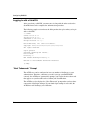
To run the configuration script, enter:
configure-radius-clients [slots <list_of_slots>] {address <address>}
{<parameter_name> <value>} ...
slots is an optional parameter that indicates which slots to configure, specified by
list_of_slots. If you do not use this parameter, the script configures all slots. Note
that you must enter the list_of_slots within braces, and separate each slot number
with a space. The BCC uses the space as a delimiter separating each of the values,
for example: {2 3 4}.
address is required for any slot that you are configuring as a RADIUS client for
the first time. address specifies the IP address of the slots.
parameter_name is the parameter you want to set, such as authentication.
value is the value you want to assign to the parameter, such as enabled.
Enter as many <parameter_name> <value> pairs as necessary.
Example:
The following command configures a RADIUS client on slots 2 and 4 of the
router at address 192.32.10.1, and enables accounting on both slots:
box# configure-radius-clients slots {2 4} address 192.32.10.1 accounting
enabled
2-8
308640-15.1 Rev 00
Chapter 3
Customizing the RADIUS Client Configuration
This chapter shows you how to change the parameter values to customize the
RADIUS client’s configuration. It includes the following topics:
Topic
Page
Modifying the Client’s IP Address
3-1
Modifying the Authentication and Accounting Services
3-3
Modifying the Protocol for RADIUS Authentication
3-5
Modifying Router Access
3-6
Removing RADIUS Authentication and Accounting
3-8
Setting the Debug Message Level
3-9
Modifying the Client’s IP Address
When a remote user makes an authentication or accounting request, the RADIUS
client passes the request along with the RADIUS client’s IP address to the server.
You can change this address, but the server will not accept the request without the
RADIUS client’s IP address.
You have already configured an IP address for the client in Chapter 2.
308640-15.1 Rev 00
3-1
Configuring RADIUS
Using the BCC
To modify the RADIUS client’s IP address, navigate to the radius-client# prompt
for the appropriate slot. Then enter the following command to modify the address
of the RADIUS client on that slot:
address <client_address>
client_address specifies the IP address of the RADIUS client.
For example, the following example configures the RADIUS client on slot 3 at IP
address 192.32.1.1:
radius-client/3# address 192.32.1.1
Note: To configure the same RADIUS configuration on one or more slots, see
“Configuring Multiple RADIUS Clients” on page 2-8.
Using Site Manager
To modify the RADIUS client’s IP address:
Site Manager Procedure
You do this
System responds
1. In the Configuration Manager window,
select Protocols > Global Protocols >
RADIUS > Edit RADIUS.
The RADIUS Client Configuration window
opens.
2. Set the Client IP Address parameter.
For more information, click on Help or see
the parameter description on page A-3.
3. Click on Done.
3-2
You return to the Configuration Manager
window.
308640-15.1 Rev 00
Customizing the RADIUS Client Configuration
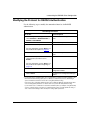
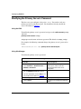
Modifying the Authentication and Accounting Services
The default for both accounting and authentication is disabled. Use the steps in
this section to:
•
Enable a slot for either accounting, authentication, or both of these services.
•
Configure the direction you want for calls generating accounting requests.
Using the BCC
When default accounting and authentication are disabled, to enable either one or
both of these services, navigate to the radius-client# prompt for the slot you want
to modify and enter one or both of the following commands:
accounting enabled
authentication enabled
For example, the following command enables accounting for the RADIUS client
on slot 2:
radius-client/2# accounting enabled
If you want to disable accounting and enable authentication to the RADIUS client,
navigate to the radius-client# prompt for the slot you want to modify and enter:
accounting disabled
authentication enabled
For example, the following commands disable accounting and enable
authentication for the RADIUS client on slot 2:
radius-client/2# accounting disabled
radius-client/2# authentication enabled
308640-15.1 Rev 00
3-3
Configuring RADIUS
To configure the RADIUS client to generate accounting requests for incoming
calls only, navigate to the radius-client# prompt for the slot you want to modify
and enter:
accounting-direction incoming
The default value is all, and the legal values are:
•
•
•
all
incoming
outgoing
For example, the following command generates accounting requests for incoming
calls on the RADIUS client on slot 2:
radius-client/2# accounting-direction incoming
Using Site Manager
To add an accounting service to the RADIUS client:
Site Manager Procedure
You do this
System responds
1. In the Configuration Manager window,
select Protocols > Global Protocols >
RADIUS > Edit RADIUS.
The RADIUS Client Configuration window
opens, which shows the slots and their
current configurations.
2. Click on the box labeled Authentication,
then select Accounting or Both.
Your selection replaces the
Authentication label.
3. If necessary, modify the client and server
addresses and protocol configurations to
accommodate the new service.
4. Click on Done.
3-4
You return to the Configuration Manager
window.
308640-15.1 Rev 00
Customizing the RADIUS Client Configuration
Modifying the Protocol for RADIUS Authentication
Use the following steps to modify the unnumbered interface for RADIUS
authentication:
Site Manager Procedure
You do this
System responds
1. In the Configuration Manager window,
select Protocols > Global Protocols >
RADIUS > Edit RADIUS.
The RADIUS Client Configuration window
opens.
2. Click on Dial-In Protocol.
The RADIUS Dial_In Slot window opens.
3. Set the Slot Number parameter.
For more information, click on Help or see
the parameter description on page A-7.
4. Click on OK.
The RADIUS Dial_In Protocol window
opens.
5. Set the enabled protocol to Disable, and
set the protocol you want to use to
Enable.*
For more information, click on Help or see
the parameter descriptions beginning on
page A-8.
6. Click on OK.
You return to the RADIUS Client
Configuration window.
7. Click on Done.
You return to the Configuration Manager
window.
* If your network uses only dial-up lines, we recommend that you enable IP together with RIP or the
Internetwork Packet Exchange (IPX) protocol. When you enable these protocols, Site Manager
opens a window that asks if the remote site is using dial-optimized routing.
If the remote site is using dial-optimized routing, click on OK. Site Manager automatically modifies
several routing update parameters so that the client can operate with dial-optimized routing.
If your network uses a combination of leased lines and dial-up lines (for example, using dial backup
service to support leased connections), it is unlikely that the routers use dial-optimized routing, so
click on Cancel. Site Manager will not modify the routing update parameters.
308640-15.1 Rev 00
3-5
Configuring RADIUS
Modifying Router Access
You can modify access to the router by enabling or disabling the user/manager
lock. The lock is disabled by default, allowing access by all users with the user or
manager profile, and also by individual users with a unique profile.
To restrict access to individual users only, access the Technician Interface and
enter the command:
set wfuserAccess.wfUserManagerLock.0 <option>
Set <option> to 1 to enable the lock; this locks out the user and manager profile,
and limits access to individual users with a unique profile.
Set <option> to 2 (default) to disable the user/manager lock, allowing access by all
users with the manager or user profile, in addition to users with a unique profile.
When you enable the user/manager lock, and a RADIUS server is unavailable for
authentication, the router automatically disables the user/manager lock. When the
RADIUS server becomes available, the router automatically enables the
user/manager lock.
Note: Be sure you configure RADIUS and assign the appropriate access to
individuals with unique profiles before you enable the user/manager lock;
otherwise you may lock out system managers from the router.
To view the current configuration of the user/manager lock, enter the command:
get wfuserAccess.wfUserManagerLock
Modifying the PPP Authentication Protocol
The remote user identifies itself to the server using one of the PPP authentication
protocols, CHAP or PAP. It includes either a CHAP name and secret or a PAP ID
and password in the access challenge to the server. CHAP is the default
authentication protocol. For more information about PPP, refer to Configuring
PPP Services.
3-6
308640-15.1 Rev 00
Customizing the RADIUS Client Configuration
To change the authentication protocol to PAP:
Site Manager Procedure
You do this
System responds
1. In the Configuration Manager window,
select Protocols > PPP > Interfaces.
The PPP Interface Lists window opens.
2. Select the Interface for Dialup Lines
record, then click on Lines.
The PPP Line Lists window opens.
3. Select PAPAUTH as the value for the
Local Authentication Protocol parameter.
4. Click on Done.
You return to the PPP Interface Lists
window.
5. Click on Done.
You return to the Configuration Manager
window.
308640-15.1 Rev 00
3-7
Configuring RADIUS
Removing RADIUS Authentication and Accounting
You can use either the BCC or Site Manager to remove RADIUS authentication
and accounting from a slot.
Using the BCC
To disable authentication and accounting on a RADIUS slot, navigate to the
radius-client# prompt for the slot you want to modify and enter:
authentication disabled
accounting disabled
For example, the following commands disable authentication and accounting for
the RADIUS client on slot 2:
radius-client/2# authentication disabled
radius-client/2# accounting disabled
Using Site Manager
To remove RADIUS authentication and accounting from a slot:
Site Manager Procedure
3-8
You do this
System responds
1. In the Configuration Manager window,
select Protocols > Global Protocols >
RADIUS > Edit RADIUS.
The RADIUS Client Configuration window
opens.
2. Click on the box labeled Authentication,
Accounting, or Both; then select None.
None replaces the previous label.
3. Click on Done.
You return to the Configuration Manager
window.
308640-15.1 Rev 00
Customizing the RADIUS Client Configuration
Setting the Debug Message Level
The debug message level determines how verbose the system is in the error
messages it sends. We recommend setting the level low so that you do not fill up
the allotted space. Then when you get a message that requires more explanation,
increase the debug message level.
Using the BCC
Navigate to the radius-client# prompt for the slot you want to modify and enter:
debug-message-level <level>
level is one of the following:
no-debug (default)
low
medium
high
For example, the following command sets the level to low for the RADIUS client
on slot 2:
radius-client/2# debug-message-level low
308640-15.1 Rev 00
3-9
Chapter 4
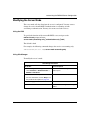
Customizing the RADIUS Server Configuration
This chapter explains how to modify the RADIUS server configuration. The
server parameters tell the client how the server is configured and define how the
client and server communicate. This chapter covers the following topics:
Topic
Page
Modifying the Primary Server’s Password
4-2
Modifying the Server Mode
4-3
Designating Authentication and Accounting UDP Ports
4-4
Modifying the Server Response Time
4-6
Modifying the Number of Client Requests to the Server
4-7
Configuring Alternate Servers
4-9
Reconnecting to the Primary Server
4-11
Changing the Primary and Alternate Servers
4-12
Removing a Server Entry
4-14
308640-15.1 Rev 00
4-1
Configuring RADIUS
Modifying the Primary Server’s Password
The first server you configure is the primary server. You can have only one
primary server for each client (router). You should have already entered the
server’s IP address in Chapter 2.
Using the BCC
To modify the primary server’s password, navigate to the radius-server# prompt
and enter:
primary-server-secret <string>
string represents the name of the new password. The default is <empty_string>.
For example, the following command changes the primary server’s password to
baynet:
radius-server/192.32.1.100# primary-server-secret baynet
Using Site Manager
To modify the primary server’s password:
Site Manager Procedure
You do this
System responds
1. In the Configuration Manager window,
select Protocols > Global Protocols >
RADIUS > Edit Server.
The RADIUS Server Configuration
window opens, which shows the
parameter defaults for the server
configuration.
2. Set the RADIUS Password parameter.
For more information, click on Help or see
the parameter description on page A-4.
4-2
3. Click on Apply (optional).
The new password replaces the old one.
4. Click on Done.
You return to the Configuration Manager
window.
308640-15.1 Rev 00
Customizing the RADIUS Server Configuration
Modifying the Server Mode
The server mode tells the client how the server is configured. You may want to
change the service from RADIUS authentication to accounting or from
accounting to authentication. You may also want to use both services.
Using the BCC
To specify the function of the current RADIUS server, navigate to the
radius-server# prompt and enter:
server-mode {accounting-only | authentication-only | both}
The default is both.
For example, the following command changes the service to accounting only:
radius-server/192.32.1.100# server-mode accounting-only
Using Site Manager
To modify the server’s mode:
Site Manager Procedure
You do this
System responds
1. In the Configuration Manager window,
select Protocols > Global Protocols >
RADIUS > Edit Server.
The RADIUS Server Configuration
window opens.
2. Set the Server Mode parameter.
For more information, click on Help or see
the parameter description on page A-4.
3. Click on Apply.
4. Click on Done.
308640-15.1 Rev 00
You return to the Configuration Manager
window.
4-3
Configuring RADIUS
Designating Authentication and Accounting UDP Ports
The User Datagram Protocol (UDP) port is the logical port that designates data for
the RADIUS application on the server. The UDP port is typically included in an
IP datagram.
The default values for the authentication and accounting UDP ports follow the
RADIUS RFC specifications. In general, you should not change these values.
Using the BCC
To designate the UDP port numbers of the RADIUS server on which it expects to
receive authentication and accounting requests, navigate to the radius-server#
prompt and enter:
authentication-udp-port <integer>
accounting-udp-port <integer>
integer is the number of the UDP port.
The default for the authentication UDP port is 1645.
The default for the accounting UDP port is 1646.
For example, the following commands specify authentication on UDP port 1645,
and accounting on UDP port 1646 for the current server:
radius-server/192.32.1.100# authentication-udp-port 1645
radius-server/192.32.1.100# accounting-udp-port 1646
4-4
308640-15.1 Rev 00
Customizing the RADIUS Server Configuration
Using Site Manager
To designate the UDP port numbers of the RADIUS server on which it expects to
receive authentication and accounting requests:
Site Manager Procedure
You do this
System responds
1. In the Configuration Manager window,
select Protocols > Global Protocols >
RADIUS > Edit Server.
The RADIUS Server Configuration
window opens.
2. Set the following parameters:
• Auth. UDP Port
• Acct. UDP Port
For more information, click on Help or see
the parameter descriptions beginning on
page A-5.
3. Click on Apply.
4. Click on Done.
308640-15.1 Rev 00
You return to the Configuration Manager
window.
4-5
Configuring RADIUS
Modifying the Server Response Time
When the client sends an accounting or authentication request to the server, you
can specify how long the client waits for a response from the server. If the client
does not receive a response, it retransmits the request. This waiting period
prevents network operations from slowing down.
Using the BCC
To specify the number of seconds the RADIUS client waits before retransmitting
a request to the RADIUS server, navigate to the radius-server# prompt and enter:
response-timeout <value>
value is an integer from 1 to 60 seconds. The default value is 3.
For example, the following command tells the RADIUS client to wait 5 seconds
before retransmitting a request to the RADIUS server:
radius-server/192.32.1.100# response-timeout 5
Using Site Manager
To modify the timeout allowed for the server before the client retransmits a
request:
Site Manager Procedure
You do this
System responds
1. In the Configuration Manager window,
select Protocols > Global Protocols >
RADIUS > Edit Server.
The RADIUS Server Configuration
window opens.
2. Set the Response Timeout parameter.
For more information, click on Help or see
the parameter description on page A-6.
3. Click on Apply.
4. Click on Done.
4-6
You return to the Configuration Manager
window.
308640-15.1 Rev 00
Customizing the RADIUS Server Configuration
Modifying the Number of Client Requests to the Server
You can modify the number of times the client sends a request to the server before
the client considers the server unreachable. If the server is located at a distance
from the client, you may want to set the number of requests to a value higher than
the default.
Note: For information on making the primary server available again, refer to
“Reconnecting to the Primary Server” on page 4-11.
Using the BCC
To specify the number of times the RADIUS client retransmits a request before it
considers the RADIUS server unreachable, navigate to the radius-server#
prompt and enter:
retry-count <value>
value is an integer from 1 to 10. The default value is 2.
For example, the following command instructs the client to retransmit a request
five times before it considers the server unreachable:
radius-server/192.32.1.100# retry-count 5
308640-15.1 Rev 00
4-7
Configuring RADIUS
Using Site Manager
To modify the number of client requests to the server:
Site Manager Procedure
You do this
System responds
1. In the Configuration Manager window,
select Protocols > Global Protocols >
RADIUS > Edit Server.
The RADIUS Server Configuration
window opens.
2. Set the Maximum Message Retry
parameter.
For more information, click on Help or see
the parameter description on page A-5.
3. Click on Apply.
4. Click on Done.
4-8
You return to the Configuration Manager
window.
308640-15.1 Rev 00
Customizing the RADIUS Server Configuration
Configuring Alternate Servers
In addition to the primary server, you can configure one or more alternate
RADIUS servers. An alternate server ensures that you can maintain network
security and accounting in case the primary server fails. You must configure a
primary server before you configure an alternate server. Then, you can configure
multiple alternate servers for each client.
Using the BCC
The RADIUS client tries to access the primary server before trying any alternate
servers. You can designate only one server as the primary for accounting and only
one for authentication. However, these two servers can be the same.
To specify the server type, navigate to the radius-server# prompt for the
appropriate server and enter:
accounting-server-type {primary | alternate}
authentication-server-type {primary | alternate}
The default for both accounting and authentication is alternate.
For example, if the same server is used for both accounting and authentication, the
following commands set the server type to primary:
radius-server/192.32.1.100# accounting-server-type primary
radius-server/192.32.1.100# authentication-server-type primary
308640-15.1 Rev 00
4-9
Configuring RADIUS
Using Site Manager
To configure an alternate server:
Site Manager Procedure
You do this
System responds
1. In the Configuration Manager window,
select Protocols > Global Protocols >
RADIUS > Edit Server.
The RADIUS Server Configuration
window opens.
2. Click on Add Alt.
The Alternate Server Address window
opens.
3. Set the following parameters:
• Server IP Address
• RADIUS Password
For more information, click on Help or see
the parameter descriptions beginning on
page A-4.
4-10
4. Click on OK.
You return to the RADIUS Server
Configuration window.
5. Click on Done.
You return to the Configuration Manager
window.
308640-15.1 Rev 00
Customizing the RADIUS Server Configuration
Reconnecting to the Primary Server
When the primary server fails to respond to connection requests, the RADIUS
client considers it unreachable and switches to the alternate server. You can
specify how long to wait before trying to reconnect to the primary server.
Using the BCC
To specify the number of minutes the RADIUS client waits before retrying the
primary server, navigate to the radius-server# prompt and enter:
reset-timer <value>
value is an integer from 1 to 60 minutes. The default is 10 minutes.
For example, the following command instructs the RADIUS client to wait 15
minutes before retrying the primary server:
radius-server/192.32.1.100# reset-timer 15
You can use the automatic-reset command in conjunction with reset-timer.
•
If automatic-reset is disabled, the RADIUS client considers the server
available after the timeout set by reset-timer.
•
If automatic-reset is enabled, the RADIUS client sends test-access requests
after the timeout set by reset-timer. When the server responds to the
test-access requests, then the client considers the server available.
To select how to make the primary server available, navigate to the
radius-server# prompt and enter:
automatic-reset {enabled | disabled}
The default is disabled.
For example, the following command enables automatic reset:
radius-server/192.32.1.100# automatic-reset enabled
308640-15.1 Rev 00
4-11
Configuring RADIUS
Using Site Manager
To try to reconnect to the primary server after a specified time period:
Site Manager Procedure
You do this
System responds
1. In the Configuration Manager window,
select Protocols > Global Protocols >
RADIUS > Edit Server.
The RADIUS Server Configuration
window opens.
2. Set the Server Reset Timer parameter.
For more information, click on Help or see
the parameter description on page A-6.
3. Click on Apply.
4. Click on Done.
You return to the Configuration Manager
window.
Changing the Primary and Alternate Servers
The RADIUS client tries to access the primary server before trying any alternate
servers. You can designate only one server as the primary for accounting and only
one for authentication. However, these two servers can be the same.
You can change the server from primary to alternate and vice versa. If you change
a server from alternate to primary, the BCC will change the original primary
server to an alternate server.
Using the BCC
To specify the accounting and authentication servers as either primary or alternate
types, navigate to the radius-server# prompt and enter:
accounting-server-type {primary | alternate}
authentication-server-type {primary | alternate}
The default for both accounting-server and authentication-server is alternate.
For example, the following commands configure both servers as primary:
radius-server/192.32.1.100# accounting-server-type primary
radius-server/192.32.1.100# authentication-server-type primary
4-12
308640-15.1 Rev 00
Customizing the RADIUS Server Configuration
Using Site Manager
To specify which server is the primary and which is the alternate:
Site Manager Procedure
You do this
System responds
1. In the Configuration Manager window,
select Protocols > Global Protocols >
RADIUS > Edit Server.
The RADIUS Server Configuration
window opens.
2. Select an alternate server entry from the
list.
3. Set the Server Mode parameter.
For more information, click on Help or see
the parameter description on page A-4.
4. Click on Primary.
Site Manager changes the entry in the
list. The alternate server is now the
primary server, and the original primary
server is now the alternate server.
5. Click on Done.
You return to the Configuration Manager
window.
308640-15.1 Rev 00
4-13
Configuring RADIUS
Removing a Server Entry
You can remove a server entry from the RADIUS configuration.
Using the BCC
To remove a server from the RADIUS configuration, navigate to the
radius-server# prompt and enter:
delete
For example, the following command removes RADIUS from the current server:
radius-server/192.32.1.100# delete
Note: To remove a RADIUS client, navigate to the radius-client prompt for
the appropriate slot and enter the delete command.
Using Site Manager
To remove a server from the RADIUS configuration:
Site Manager Procedure
You do this
System responds
1. In the Configuration Manager window,
select Protocols > Global Protocols >
RADIUS > Edit Server.
The RADIUS Server Configuration
window opens.
2. Select a server entry from the list.
4-14
3. Click on Delete.
Site Manager removes the entry from the
list.
4. Click on Done.
You return to the Configuration Manager
window.
308640-15.1 Rev 00
Appendix A
Site Manager Parameters
This appendix describes the Site Manager RADIUS parameters. You can display
the same information using Site Manager online Help.
This appendix contains the following information:
Topic
Page
Client IP Address Parameter
A-2
Server Configuration Parameters
A-3
Protocol Parameters for RADIUS Authentication
A-7
For each parameter, this appendix provides the following information:
•
Parameter name
•
Configuration Manager menu path
•
Default setting
•
Valid parameter options
•
Parameter function
•
Instructions for setting the parameter
•
Management information base (MIB) object ID
308640-15.1 Rev 00
A-1
Configuring RADIUS
You can also use the Technician Interface to modify parameters by issuing set and
commit commands with the MIB object ID. This process is the same as
modifying parameters using Site Manager. For information about using the
Technician Interface to access the MIB, refer to Using Technician Interface
Software.
Caution: The Technician Interface does not verify that the value you enter for
a parameter is valid. Entering an invalid value can corrupt your configuration.
Client IP Address Parameter
The RADIUS Client Configuration window (Figure A-1) shows the current
RADIUS configuration for each slot on the router.
Figure A-1.
A-2
RADIUS Client Configuration Window
308640-15.1 Rev 00
Site Manager Parameters
Parameter: Client IP Address
Path: Protocols > Global Protocols > RADIUS > Create RADIUS
or
Protocols > Global Protocols > RADIUS > Edit RADIUS
Default: None
Options: A 32-bit IP address
Function: Identifies the RADIUS client.
Instructions: Enter a valid IP address of a configured and operational IP interface that you
want to designate as the RADIUS client.
MIB Object ID: 1.3.6.1.4.1.18.3.5.22.1.1.5
Server Configuration Parameters
The RADIUS Server Configuration window (Figure A-2) shows the current
parameter settings for the RADIUS server configuration.
Figure A-2.
308640-15.1 Rev 00
RADIUS Server Configuration Window
A-3
Configuring RADIUS
Parameter: Server IP Address
Path:
Default:
Options:
Function:
Instructions:
MIB Object ID:
Protocols > Global Protocols > RADIUS > Edit Server
None
A 32-bit IP address
Identifies the RADIUS server.
Enter an IP address that you want to designate as the RADIUS server.
1.3.6.1.4.1.18.3.5.22.2.1.3
Parameter: Server Mode
Path:
Default:
Options:
Function:
Instructions:
Protocols > Global Protocols > RADIUS > Edit Server
Both
Authentication | Accounting | Both
Specifies the RADIUS operation for this port.
Select the service you want for this port. If you want to configure both
authentication and accounting, select Both.
MIB Object ID: 1.3.6.1.4.1.18.3.5.22.2.1.4
Parameter: RADIUS Password
Path:
Default:
Options:
Function:
Protocols > Global Protocols > RADIUS > Edit Server
None
An alphanumeric string, to a maximum of 64 characters
Identifies the client to the server. The client and server must use the same
password.
Instructions: Enter a password that contains a maximum of 64 characters.
MIB Object ID: 1.3.6.1.4.1.18.3.5.22.2.1.11
A-4
308640-15.1 Rev 00
Site Manager Parameters
Parameter: Auth. UDP Port
Path:
Default:
Options:
Function:
Protocols > Global Protocols > RADIUS > Edit Server
1645
An integer specifying the UDP logical port for authentication
Designates a data packet for RADIUS authentication. This number is required
for access to the authentication server.
Instructions: Accept the default value.
MIB Object ID: 1.3.6.1.4.1.18.3.5.22.2.1.6
Parameter: Acct. UDP Port
Path:
Default:
Options:
Function:
Protocols > Global Protocols > RADIUS > Edit Server
1646
An integer specifying the UDP logical port for accounting
Designates a data packet for RADIUS accounting. This number is required for
access to the accounting server.
Instructions: Accept the default value.
MIB Object ID: 1.3.6.1.4.1.18.3.5.22.2.1.9
Parameter: Maximum Message Retry
Path:
Default:
Options:
Function:
Protocols > Global Protocols > RADIUS > Edit Server
2
1 to 10
Specifies the number of times the RADIUS client retransmits a request before it
considers the RADIUS server unreachable.
Instructions: Enter the number of times you want the client to retransmit a request.
MIB Object ID: 1.3.6.1.4.1.18.3.5.22.2.1.13
308640-15.1 Rev 00
A-5
Configuring RADIUS
Parameter: Response Timeout (seconds)
Path:
Default:
Options:
Function:
Protocols > Global Protocols > RADIUS > Edit Server
3
1 to 60 seconds
Specifies the number of seconds the RADIUS client waits before retransmitting
a request to the RADIUS server.
Instructions: Accept the default or enter a number of seconds from 1 to 60.
MIB Object ID: 1.3.6.1.4.1.18.3.5.22.2.1.12
Parameter: Server Reset Timer (minutes)
Path:
Default:
Options:
Function:
Protocols > Global Protocols > RADIUS > Edit Server
10
1 to 60 minutes
Specifies the number of minutes the RADIUS client waits before retrying the
primary server after it fails to respond. If the primary server fails to respond, the
client considers it unreachable and switches to the alternate server. After this
specified time period, the client tries to reconnect to the primary server.
Instructions: Accept the default or enter the number of minutes you want the client to wait for
the primary server to recover.
MIB Object ID: 1.3.6.1.4.1.18.3.5.22.2.1.14
A-6
308640-15.1 Rev 00
Site Manager Parameters
Protocol Parameters for RADIUS Authentication
The RADIUS Dial_In Protocol window (Figure A-3) shows the current protocol
settings. These protocols are only for RADIUS authentication.
Figure A-3.
RADIUS Dial_In Protocol Window
Parameter: Slot Number
Path: Protocols > Global Protocols > RADIUS > Edit RADIUS > Dial-In Protocol >
RADIUS Dial_In Slot> RADIUS Dial_In Protocol
Default: None
Options: An integer that represents a router slot configured for RADIUS
Function: Identifies the slot configured for RADIUS.
Instructions: Enter the slot number that you want to configure.
MIB Object ID: 1.3.6.1.4.1.18.3.5.22.1.1.4
308640-15.1 Rev 00
A-7
Configuring RADIUS
Parameter: IP Enable
Path: Protocols > Global Protocols > RADIUS > Edit RADIUS > Dial-In Protocol >
RADIUS Dial_In Slot > RADIUS Dial_In Protocol
Default: Disable
Options: Enable | Disable
Function: Enables or disables IP on this interface.
Instructions: Select Enable to enable IP on this interface.
MIB Object ID: 1.3.6.1.4.1.18.3.5.1.4.12.1.5
Parameter: RIP Enable
Path: Protocols > Global Protocols > RADIUS > Edit RADIUS > Dial-In Protocol >
RADIUS Dial_In Slot > RADIUS Dial_In Protocol
Default: Disable
Options: Enable | Disable
Function: Enables or disables RIP on this interface.
Instructions: Select Enable to enable RIP on this interface.
MIB Object ID: 1.3.6.1.4.1.18.3.5.1.4.12.1.7
Parameter: OSPF Enable
Path: Protocols > Global Protocols > RADIUS > Edit RADIUS > Dial-In Protocol >
RADIUS Dial_In Slot > RADIUS Dial_In Protocol
Default: Disable
Options: Enable | Disable
Function: Enables or disables OSPF on this interface.
Instructions: Select Enable to enable OSPF on this interface.
MIB Object ID: 1.3.6.1.4.1.18.3.5.1.4.12.1.8
A-8
308640-15.1 Rev 00
Site Manager Parameters
Parameter: IPX Enable
Path: Protocols > Global Protocols > RADIUS > Edit RADIUS > Dial-In Protocol >
RADIUS Dial_In Slot > RADIUS Dial_In Protocol
Default: Disable
Options: Enable | Disable
Function: Enables or disables IPX on this interface.
Instructions: Select Enable to enable IPX on this interface.
MIB Object ID: 1.3.6.1.4.1.18.3.5.1.4.12.1.9
Parameter: IPXWAN Enable
Path: Protocols > Global Protocols > RADIUS > Edit RADIUS > Dial-In Protocol >
RADIUS Dial_In Slot > RADIUS Dial_In Protocol
Default: Disable
Options: Enable | Disable
Function: Enables or disables IPXWAN on this interface.
Instructions: Select Enable to enable IPXWAN on this interface.
MIB Object ID: 1.3.6.1.4.1.18.3.5.1.4.12.1.13
Parameter: Bridge Enable
Path: Protocols > Global Protocols > RADIUS > Edit RADIUS > Dial-In Protocol >
RADIUS Dial_In Slot > RADIUS Dial_In Protocol
Default: Disable
Options: Enable | Disable
Function: Enables or disables bridging on this interface.
Instructions: Select Enable to enable bridging on this interface.
MIB Object ID: 1.3.6.1.4.1.18.3.5.1.4.12.1.10
308640-15.1 Rev 00
A-9
Appendix B
Monitoring RADIUS Using the
BCC show Commands
Use the BCC show commands to display configuration and statistical information
about RADIUS. See Using the Bay Command Console (BCC) for information
about show command syntax.
This appendix describes the following show commands:
Command
Page
show radius alerts
B-3
show radius clients
B-4
show radius servers general
B-5
show radius servers timers
B-6
show radius stats accounting
B-7
show radius stats authentication
B-8
308640-15.1 Rev 00
B-1
Configuring RADIUS
Online Help for show Commands
To display a list of command options, enter one of these commands at any BCC
prompt:
•
show radius alerts ?
•
show radius clients ?
•
show radius servers ?
•
show radius stats ?
To learn more about any show command option and its syntax, use the question
mark (?) command as follows:
Example
bcc> show radius servers ?
general
timers
bcc> show radius servers timers ?
show radius servers timers [-address <arg>]
bcc>
B-2
308640-15.1 Rev 00
Monitoring RADIUS Using the BCC show Commands
show radius alerts
The show radius alerts command displays problems with the RADIUS
configuration.
You can use the following filter flag and argument with this command:
-address <address> Displays information about the server at the specified IP
address only.
The output contains the following information:
Server IP Address
Lists the IP address of the primary RADIUS server.
Server Mode
Displays the mode: authentication, accounting, or both.
Server Type
Specifies whether the server is primary or alternate.
Authentication State
Indicates whether authentication is operational or not.
Accounting State
Indicates whether accounting is operational or not.
308640-15.1 Rev 00
B-3
Configuring RADIUS
show radius clients
The show radius clients command displays information about the router’s
RADIUS configuration.
You can use the following filter flag and argument with this command:
-slot <slot>
Displays information about the RADIUS configuration in a
specific slot.
The output contains the following information:
B-4
Slot
Specifies the slot number in the RADIUS client.
Client IP Address
Lists the IP address of the RADIUS client.
Authentication State
Indicates whether authentication is enabled or disabled.
Accounting State
Indicates whether accounting is enabled or disabled.
Accounting Direction
Shows which calls generate accounting requests: incoming,
outgoing, or all.
Debug Message Level
Displays the message debug level: no-debug, low, medium, or
high.
308640-15.1 Rev 00
Monitoring RADIUS Using the BCC show Commands
show radius servers general
The show radius servers general command displays information about the
overall state of the RADIUS server.
You can use the following filter flag and argument with this command:
-address <address>
Displays information about the server at the specified IP
address only.
The output contains the following information:
Server IP Address
Lists the IP address of the RADIUS server.
Server Mode
Displays the mode configured for this server:
authentication, accounting, or both.
Server Secret
Displays the password configured for this server.
Authentication Type
Indicates whether this is a primary or alternate server for
authentication.
Authentication State
Indicates whether this server is enabled or disabled for
authentication.
Authentication UDP Port
Displays the UDP port number configured for authentication
requests sent to this server.
Accounting Type
Indicates whether this is a primary or alternate server for
accounting.
Accounting State
Indicates whether accounting is enabled or disabled.
Accounting UDP Port
Displays the UDP port number configured for accounting
requests sent to this server.
308640-15.1 Rev 00
B-5
Configuring RADIUS
show radius servers timers
The show radius servers timers command displays the time-setting information
for the RADIUS server.
You can use the following filter flag and argument with this command:
-address <address>
Displays information about the server at the specified IP
address only.
The output contains the following information:
B-6
Server IP Address
Lists the IP address of the primary RADIUS server.
Response Timeout
Specifies how many seconds the client should wait before
retransmitting a request to the server.
Maximum Retry
Specifies how many times the client should send a request
to the server before considering it unreachable.
Reset Timer
Specifies how many minutes the client should wait before
trying to reconnect to the primary server.
Automatic Reset
Indicates whether automatic reset is enabled or disabled.
308640-15.1 Rev 00
Monitoring RADIUS Using the BCC show Commands
show radius stats accounting
The show radius stats accounting command displays all the RADIUS
statistical information related to accounting.
You can use the following filter flags and arguments with this command:
-address <address>
Displays information about the server at the specified IP
address only.
-slot <slot>
Displays information about the RADIUS configuration in a
specific slot.
The output contains the following information:
Server IP Address
Lists the IP address of the primary RADIUS server.
Slot
Specifies the slot number in the RADIUS client.
Accounting Requests Start
Indicates the number of accounting requests starting.
Accounting Requests Stop
Indicates the number of accounting requests stopping.
Accounting Response
Indicates the number of accounting responses from the
accounting server.
Accounting Response
Timeouts
Indicates the number of accounting requests that timed out
before the accounting server could respond.
Accounting Response
Failed
Indicates the number of accounting requests that the
accounting server did not respond to.
Accounting Alternate Server
Retries
Indicates the number of times the client had to use the
alternate server.
308640-15.1 Rev 00
B-7
Configuring RADIUS
show radius stats authentication
The show radius stats authentication command displays all the RADIUS
statistical information related to authentication.
You can use the following filter flags and arguments with this command:
-address <address>
Displays information about the server at the specified IP
address only.
-slot <slot>
Displays information about the RADIUS configuration in a
specific slot.
The output contains the following information:
B-8
Server IP Address
Lists the IP address of the primary RADIUS server.
Slot
Specifies the slot number in the RADIUS client.
Authentication Requests
Count
Indicates the total number of RADIUS authentication
requests that the client in this slot made to this server.
Authentication Requests
Outstanding
Indicates the number of outstanding RADIUS
authentication requests that the client in this slot made to
this server.
Authentication Responses
Accept
Indicates the number of successful RADIUS authentication
requests that the client in this slot made to this server.
Authentication Responses
Reject
Indicates the number of failed RADIUS authentication
requests that the client in this slot made to this server.
Authentication Responses
No Response
Indicates the number of times that the server sent an
“invalid user” or “no server available” response to a
RADIUS authentication request from the client in this slot.
Authentication Responses
Invalid
Indicates the number of times that the server sent an
“invalid user” response to a RADIUS authentication
request from the client in this slot.
Authentication Responses
Timeouts
Indicates the number of times that the server timed out
before it could respond to a RADIUS authentication
request from the client in this slot.
Authentication Alternate
Server Retries
Indicates the number of times that the client in this slot
requested an alternate server because the primary server
was unreachable.
308640-15.1 Rev 00
Appendix C
Configuration Examples
This appendix provides the following configuration examples for a router acting
as a RADIUS client:
•
Configuring RADIUS authentication
•
Configuring RADIUS accounting
•
Configuring RADIUS authentication and accounting
The examples in this appendix show only those parameters whose defaults you
must change for proper configuration.
Topic
Page
Configuring RADIUS Authentication
C-2
Configuring RADIUS Accounting
C-6
Configuring RADIUS Accounting and Authentication
C-12
308640-15.1 Rev 00
C-1
Configuring RADIUS
Configuring RADIUS Authentication
This example shows how to configure the router as a RADIUS authentication
client, and assumes the following:
•
The client is a BLN router.
•
The network connections are all raise DTR modem connections.
•
The WAN serial interface type is synchronous.
•
IP and RIP are the protocols for the client’s unnumbered circuit interface.
•
Dial-optimized routing and one-way authentication are configured on the
remote routers.
•
A default route of 0.0.0.0 is configured on the remote routers to contact the
client.
M
O
DE
M
Figure C-1 shows the sample network for this example.
POTS
Remote
user A
M
O
DE
M
RADIUS server
IP address: 192.32.24.7
Remote
user B
POTS
RADIUS client
IP address: 192.32.24.6
CR0002A
Figure C-1.
Sample Network Using RADIUS Authentication
The next sections explain how to configure the sample network using the BCC
and Site Manager.
C-2
308640-15.1 Rev 00
Configuration Examples
Using the BCC
To enable RADIUS and configure the IP addresses for a RADIUS client and
server:
1.
Start configuration mode by entering:
bcc> config
2.
Configure RADIUS on the box by entering:
box# radius
3.
Configure the RADIUS client on slot 3 and address 192.32.24.6 by
entering:
radius# radius-client slot 3 address 192.32.24.6
4.
Enable authentication for the RADIUS client on slot 3 by entering:
radius-client/3# authentication enabled
5.
Navigate to the top-level RADIUS prompt by entering:
radius-client/3# back
6.
Configure the RADIUS server on address 192.32.24.7 by entering:
radius# radius-server address 192.32.24.7
7.
Change the authentication-server-type to primary by entering:
radius-server/192.32.24.7# authentication-server-type primary
8.
Configure the primary-server-secret to baynet by entering:
radius-server/192.32.24.7# primary-server-secret baynet
Using Site Manager
Before you begin, do the following:
1.
Create and save a configuration file with at least one PPP interface.
2.
Retrieve the configuration file in local, remote, or dynamic mode.
3.
Specify the router hardware if this is a local-mode configuration.
308640-15.1 Rev 00
C-3
Configuring RADIUS
To configure the sample network:
Site Manager Procedure
You do this
System responds
1. In the Configuration Manager window,
select Protocols > Global Protocols >
RADIUS > Create RADIUS.
The RADIUS Client Configuration window
opens, which shows the router slots
available for configuring RADIUS.
2. Click on one of the boxes labeled None.
The menu opens showing the RADIUS
options.
3. Select Authentication for the slot.
Authentication replaces the label None.
4. Select the COM connectors that you want Site Manager enables the connectors for
to serve as RADIUS interfaces.
RADIUS operation.
5. Click on OK to accept the default settings
for all windows until you return to the
RADIUS Client Configuration window.
You return to the RADIUS Client
Configuration window. Notice the letters
DR next to the names of the connectors
you configured. This indicates that the
connector is now a RADIUS interface.
6. Set the Client IP Address parameter to
192.32.24.6.
7. At the bottom of the RADIUS Client
Configuration window, click on Server.
The Primary Server Address window
opens.
8. Set the Server IP Address parameter to
192.32.24.7.
9. Set the RADIUS Password parameter to
Client_BLN.
10. Click on OK.
The RADIUS Server Configuration
window opens, which shows the
parameter defaults for the server.
11. Accept the defaults and click on Done.
You return to the RADIUS Client
Configuration window.
12. Go to the next table to select IP.
C-4
308640-15.1 Rev 00
Configuration Examples
To select IP:
Site Manager Procedure
You do this
System responds
1. At the bottom of the RADIUS Client
Configuration window, click on Dial-In
Protocol.
The RADIUS Dial_In Slot window opens.
2. Enter the number of the slot configured for
authentication.
3. Click on OK.
The RADIUS Dial_In Protocol window
opens.
4. Set the IP Enable parameter to Enable.
For more information, click on Help or see
the parameter description on page A-8.
5. Set the RIP Enable parameter to Enable.
For more information, click on Help or see
the parameter description on page A-8.
6. Click on OK.
Site Manager displays a window that
asks if the remote site is using
dial-optimized routing. The remote
routers in this example are using
dial-optimized routing.
7. Click on OK.
You return to the RADIUS Client
Configuration window.
8. Click on Done.
You return to the Configuration Manager
window.
308640-15.1 Rev 00
C-5
Configuring RADIUS
Configuring RADIUS Accounting
This example explains how to configure the router as a RADIUS accounting
client, and assumes the following:
•
The client is an ASN router.
•
Dial backup is the dial service.
•
The RADIUS client only receives calls, it does not make calls; therefore, you
do not need to configure an outgoing phone list and local CHAP name and
secret for the client.
•
The leased and dial backup connections use PPP.
•
The WAN serial interface type is synchronous.
•
RADIUS authentication is not configured on the client.
Figure C-2 shows the sample network for this example.
Site A
ISDN
Remote users
RADIUS server
IP address: 192.32.24.3
Site B
ISDN
RADIUS client
IP address: 192.32.24.2
Remote users
Key
Primary line
Backup line
Figure C-2.
C-6
CR0003A
Sample Network Using RADIUS Accounting
308640-15.1 Rev 00
Configuration Examples
The next sections explain how to configure the sample network using the BCC
and Site Manager.
Using the BCC
To enable RADIUS accounting on a RADIUS client, complete the following
steps. (For more information on configuring ISDN interfaces, refer to Configuring
Dial Services.)
1.
Start configuration mode by entering:
bcc> config
2.
To configure two B channels and one D channel on the interface, enter:
stack# bri 3/1 mode 2b+d
3.
Navigate to the channel prompt and make the BRI interface 3/1 a dial
object by entering:
channel/3/1# dial
4.
Navigate to the backup-pool prompt and add a backup line to the pool by
entering:
backup-pool/8# backup-line bri/3/1
5.
Navigate to the isdn-switch prompt and specify the switch type by
entering:
isdn-switch/3# switch-type brini1
6.
Navigate to the leased interface prompt for slot 2, connector 1 and create
a backup circuit with a backup mode by entering:
ppp/2/1# backup-circuit pool-id 8 backup-mode initiator
7.
Navigate to the backup circuit prompt and configure CHAP name
“bayrs1” and secret “east” for the backup circuit by entering:
backup-circuit/8/1/1# chap-name bayrs1 chap-secret east
8.
Navigate to the stack prompt and configure RADIUS accounting by
entering:
stack# radius
9.
To configure the RADIUS client on slot 2, address 192.32.24.2, enter:
radius# radius-client slot 2 address 192.32.24.2
308640-15.1 Rev 00
C-7
Configuring RADIUS
10. To enable RADIUS accounting for the RADIUS client on slot 2, enter:
radius-client/2# accounting enabled
11. Navigate to the top-level RADIUS prompt by entering:
radius-client/2# back
12. To configure the RADIUS server on address 192.32.24.3, enter:
radius# radius-server address 192.32.24.3
13. Change the authentication-server-type to primary by entering:
radius-server/192.32.24.3# authentication-server-type primary
14. Configure the primary-server-secret to baynet by entering:
radius-server/192.32.24.3# primary-server-secret baynet
Using Site Manager
Before you begin, do the following:
1.
Create and save a configuration file with at least one PPP interface.
2.
Retrieve the configuration file in local, remote, or dynamic mode.
3.
Specify the router hardware if this is a local-mode configuration.
To create a backup pool:
Site Manager Procedure
You do this
System responds
1. In the Configuration Manager window,
select an ISDN connector.
The Port Application window opens.
2. Click on OK to accept the default for the
Port Application Mode parameter, Dialup
2B + D.
This configures the BRI interface. Repeat
Steps 1 and 2 to configure additional BRI
interfaces.
3. Select Dialup > Backup Pools.
The Backup Pools window opens.
4. Click on Add.
The Backup Pools Configuration window
opens.
5. Enter a pool ID, then click on OK.
The Backup Lines Definition window
opens.
(continued)
C-8
308640-15.1 Rev 00
Configuration Examples
Site Manager Procedure (continued)
You do this
System responds
6. Click on an ISDN connector to assign a
The ISDN Switch Configuration window
line to the pool, following these guidelines: opens.
• Site Manager does not allow you to
select any lines that you configured as
leased lines.
• Lines in a backup pool may reside
across slots.
7. Click on Done to accept the parameter
defaults.
The ISDN Logical Lines window opens.
8. Click on OK to accept the parameter
defaults.
You return to the Backup Lines Definition
window. The letter B (backup) appears
next to the ISDN port to indicate that it is
a backup line.
9. Select File > Exit to exit the Backup Lines You return to the Backup Pools window,
Definition window.
which has three new buttons (Edit, Apply,
and Delete) that allow you to edit the new
pool.
10. Repeat Steps 3 through 9 to select
additional lines for the pool.
11. Click on Done.
308640-15.1 Rev 00
You return to the Configuration Manager
window.
C-9
Configuring RADIUS
To create a backup circuit:
Site Manager Procedure
You do this
System responds
1. In the Configuration Manager window,
select Backup Circuits > PPP.
The Primary Circuit Definition window
opens, which lists the leased circuits that
you have configured.
2. Select a circuit entry and click on Cct
Type.
The Circuit Options window opens.
3. Enter Primary for the Circuit Type
parameter.
4. Enter the ID of the backup pool that this
circuit should use.
5. Click on OK.
The Primary Circuit Definition window,
which shows the parameter defaults
supplied by Site Manager, reopens.
6. Repeat Steps 2 through 5 to specify
additional primary circuits.
7. Scroll down the Primary Circuit Definition
window to the Backup Mode parameter.
8. Select a value for the Backup Mode
parameter. The default is Master.
If this router is the master router, the peer
router’s backup mode must be set to
Slave. If you set the backup mode to
Slave, Site Manager prompts you for
caller resolution information so the slave
router can verify the identity of a remote
caller.
Refer to Configuring Dial Services for more information about dial backup
circuits.
C-10
308640-15.1 Rev 00
Configuration Examples
To enable RADIUS accounting:
Site Manager Procedure
You do this
System responds
1. In the Configuration Manager window,
select Protocols > Global Protocols >
RADIUS > Create RADIUS.
The RADIUS Client Configuration window
opens, which shows the router slots
available for configuring RADIUS.
2. To configure a slot for RADIUS, click on
the box labeled None.
Site Manager displays a menu showing
the RADIUS options.
3. Select Accounting for the slot.
4. Set the Client IP Address parameter to
192.32.24.2.
5. Click on Server at the bottom of the
window.
The Primary Server Address window
opens.
6. Set the Server IP Address parameter to
192.32.24.3.
7. Set the RADIUS Password parameter to
Client_ASN, then click on OK.
The RADIUS Server Configuration
window opens, which shows the default
configuration for the server.
8. Accept the defaults for the server
configuration parameters.
9. Click on Done.
You return to the RADIUS Client
Configuration window.
10. Click on Done.
You return to the Configuration Manager
window.
308640-15.1 Rev 00
C-11
Configuring RADIUS
Configuring RADIUS Accounting and Authentication
This example explains how to configure the router as a RADIUS accounting and
authentication client. The sample network shows a remote router dialing an
alternate site when the original destination is not accessible. The example assumes
the following:
•
The client is an ASN.
•
Dial backup is the dial service.
•
The leased connections are using Frame Relay.
•
The backup connections are using PPP.
•
IP and RIP are the protocols for the client’s unnumbered circuit interface.
Figure C-3 shows the sample network for this example.
Branch office
R2
Regional router
R1
Frame
relay
CHAP local name = R2
Configured with dial backup
Branch office
CHAP local name = R1
R3
CHAP local name = R3
Configured with dial backup
RADIUS server
IP address:
192.32.24.3
Branch office
Recovery router R5
ISDN
RADIUS client
IP address: 192.32.24.4
Configured with authentication
and accounting
R4
CHAP local name = R4
Configured with dial backup
Key
Primary circuits
Backup circuits
Figure C-3.
C-12
CR0004A
Sample Network Configured for Dialing an Alternate Site
308640-15.1 Rev 00
Configuration Examples
The next sections explain how to configure the sample network using the BCC
and Site Manager.
Using the BCC
To enable RADIUS accounting and authentication on a RADIUS client, use the
following steps:
1.
Start configuration mode by entering:
bcc> config
2.
Configure RADIUS on the box by entering:
box# radius
3.
To configure the RADIUS client on slot 3, address 192.32.24.4, enter:
radius# radius-client slot 3 address 192.32.24.4
4.
To enable RADIUS authentication and accounting for the RADIUS client
on slot 3, enter the following commands:
radius-client/3# authentication enabled
radius-client/3# accounting enabled
5.
Navigate to the top-level RADIUS prompt by entering:
radius-client/3# back
6.
To configure the RADIUS server on address 192.32.24.3, enter:
radius# radius-server address 192.32.24.3
7.
Change the authentication-server-type to primary by entering:
radius-server/192.32.24.3# authentication-server-type primary
8.
Configure the primary-server-secret to baynet by entering:
radius-server/192.32.24.3# primary-server-secret baynet
Using Site Manager
Before you begin, do the following:
1.
Create and save a configuration file with at least one PPP interface.
2.
Retrieve the configuration file in local, remote, or dynamic mode.
3.
Specify the router hardware if this is a local-mode configuration.
308640-15.1 Rev 00
C-13
Configuring RADIUS
To configure the RADIUS client and server, and enable RADIUS authentication
and accounting on a router slot:
Site Manager Procedure
You do this
System responds
1. In the Configuration Manager window,
select Protocols > Global Protocols >
RADIUS > Create RADIUS.
The RADIUS Client Configuration window
opens, which shows the router slots
available for configuring RADIUS.
2. Click on one of the boxes labeled None.
The menu opens showing the RADIUS
options.
3. Select Both for the slot.
Both replaces the label None.
4. Select the connectors that you want to
configure as authentication interfaces.
5. Click on OK to accept the default settings
for all windows until you return to the
RADIUS Client Configuration window.
You return to the RADIUS Client
Configuration window. Notice the letters
DR next to the names of the connectors
you configured. This indicates that the
connector is now a RADIUS interface.
6. Set the Client IP Address parameter to
192.32.24.4.
7. At the bottom of the RADIUS Client
Configuration window, click on Server.
The Primary Server Address window
opens.
8. Set the Server IP Address parameter to
192.32.24.3.
9. Set the RADIUS Password parameter to
Client_ASN.
10. Click on OK.
The RADIUS Server Configuration
window opens, which shows the
parameter defaults for the server.
11. Accept the defaults and click on Done.
You return to the RADIUS Client
Configuration window.
12. Go to the next table to select IP.
C-14
308640-15.1 Rev 00
Configuration Examples
To select IP:
Site Manager Procedure
You do this
System responds
1. At the bottom of the RADIUS Client
Configuration window, click on Dial-In
Protocol.
The RADIUS Dial_In Slot window opens.
2. Enter the number of the slot configured for
RADIUS.
3. Click on OK.
The RADIUS Dial_In Protocol window
opens.
4. Set the IP Enable parameter to Enable.
5. Set the RIP Enable parameter to Enable.
6. Click on OK.
Site Manager displays a window that
asks if the remote site is using dial
optimized routing. The remote routers in
this example are using dial optimized
routing.
7. Click on OK.
You return to the RADIUS Client
Configuration window.
8. Click on Done.
You return to the Configuration Manager
window.
308640-15.1 Rev 00
C-15
Appendix D
Vendor-Specific Attributes
This appendix shows the Nortel Networks vendor-specific attributes (VSAs) and
the dictionary file that contains them.
Topic
Page
Nortel Networks Vendor-Specific Attributes
D-2
RADIUS Dictionary File
D-3
308640-15.1 Rev 00
D-1
Configuring RADIUS
Nortel Networks Vendor-Specific Attributes
The Nortel Networks vendor ID is 1584, as allocated by the Internet Assigned
Numbers Authority. Use this ID in the header when using VSAs.
Table D-1 lists the Nortel Networks RADIUS VSAs and the applications that use
them.
Table D-1.
D-2
Nortel Networks VSAs
Application
VSA Name
VSA Number
Dial Services
Bay-Local-IP-Address
35
L2TP
Bay-Primary-DNS-Server
Bay-Secondary-DNS-Server
Bay-Primary-NBNS-Server
Bay-Secondary-NBNS-Server
54
55
56
57
Multilevel Access
Bay-User-Level
• Manager
2
• User
4
• Operator
8
100
Bay-Audit-Level
• Manager
2
• User
4
• Operator
8
101
308640-15.1 Rev 00
Vendor-Specific Attributes
RADIUS Dictionary File
This section shows the contents of the RADIUS dictionary file (bayrs.dct) for
reference purposes only. This dictionary file defines the Nortel Networks VSAs.
If you have a BaySecure Access Control (BSAC) server, copy the following three
files from the CD that comes with the server to the directory that you define at
installation time (usually C:\RADIUS\Service).
•
bayrs.dct
•
vendor.ini
•
dictiona.dcm
If you do not have a Nortel Networks server, use the RADIUS dictionary file as a
reference to change your existing RADIUS dictionaries. Because this file is in the
format of some popular RADIUS servers, you may be able to use it as a direct
replacement. However, you should review the dependencies and make a decision
on how to apply the differences.
bayrs.dct - Nortel Networks BayRS dictionary
This dictionary contains BayRS Router Specific Attributes
(See README.DCT for more details on the format of this file.)
Use the Radius specification attributes
@radius.dct
Define Nortel Networks BayRS Family Attributes
MACRO Bay-VSA (t,s) 26 [vid=1584 type1=%t% len1=+2 data=%s%]
Attribute used with dial services
ATTRIBUTE
308640-15.1 Rev 00
Bay-Local-IP-Address
Bay-VSA (35, ipaddr) r
D-3
Configuring RADIUS
Attributes used with l2tp
ATTRIBUTE
Bay-Primary-DNS-Server
Bay-VSA (54, ipaddr) r
ATTRIBUTE
Bay-Secondary-DNS-Server
Bay-VSA (55, ipaddr) r
ATTRIBUTE
Bay-Primary-NBNS-Server
Bay-VSA (56, ipaddr) r
ATTRIBUTE
Bay-Secondary-NBNS-Server
Bay-VSA (57, ipaddr) r
Attributes used with multi user access
D-4
ATTRIBUTE
Bay-User-Level
Bay-VSA (100, integer) R
VALUE
Bay-User-Level Manager
2
VALUE
Bay-User-Level User
4
VALUE
Bay-User-Level Operator
8
ATTRIBUTE
Bay-Audit-Level
VALUE
Bay-Audit-Level Manager
2
VALUE
Bay-Audit-Level User
4
VALUE
Bay-Audit-Level Operator
8
Bay-VSA (101, integer) R
308640-15.1 Rev 00
Appendix E
Configuring RADIUS with SecurID
Use the information in this appendix if you are using SecurID for RADIUS
authentication.
This appendix includes information about the following topics:
Topic
Page
Configuring RADIUS Client and ACE/Server Attributes on the Router
E-2
Configuring the ACE/Server
E-8
Establishing User Authentication
E-8
308640-15.1 Rev 00
E-1
Configuring RADIUS
Configuring RADIUS Client and ACE/Server Attributes
on the Router
You can use the BCC or Site Manager to configure RADIUS Client and
ACE/Server attributes on the router.
Using the BCC
To enable RADIUS services and configure ACE/Server attributes on the router
using the BCC, complete the following tasks:
1.
Start the BCC and enter configuration mode.
# bcc
bcc> config
box#
2.
Configure RADIUS on the router.
box# radius
radius#
3.
Configure a slot and address for the RADIUS client.
radius# radius-client slot <slot_number> address <client_address>
slot_number specifies the router slot that you want to configure for RADIUS.
client_address specifies the IP address of the RADIUS client.
For example, the following command sequence configures the RADIUS
client on slot 3, at the IP address 192.32.1.1, and displays the default values
for all RADIUS parameters:
radius# radius-client slot 3 address 192.32.1.1
radius/client/3# info
slot 3
address 192.32.1.1
debug-message-level no-debug
authentication disabled
accounting disabled
accounting-direction all
4.
Enable authentication for the RADIUS client.
radius/client/3# authentication enabled
radius/client/3#
E-2
308640-15.1 Rev 00
Configuring RADIUS with SecurID
5.
Accept the remaining default parameter values for the RADIUS client or
modify them to customize the RADIUS client’s configuration.
6.
Navigate to the top-level RADIUS prompt.
radius-client/3# back
radius#
7.
Specify the IP address for the ACE/Server.
radius# radius-server address <server_address>
server_address specifies the IP address of the ACE/Server.
For example, the following command configures the ACE/Server for
authentication at the IP address 192.32.10.1:
radius# radius-server address 192.32.10.1
radius-server/192.32.10.1#
8.
Change the server response time.
By default, the RADIUS client waits 3 seconds for a server to respond to an
authentication request. The ACE/Server, however, requires additional time to
respond to authentication requests. Therefore, you must increase the response
time to a minimum of 10 seconds. If your network accommodates a high level
of traffic, you may need to increase the response time to 30 seconds.
To increase the response time, enter:
response-timeout <value>
value specifies the response time in seconds.
For example, the following command configures the RADIUS client to wait
10 seconds before retransmitting a request to the ACE/Server:
radius-server/192.32.1.100# response-timeout 10
9.
Set the authentication server type.
You must designate one RADIUS server as the primary server for
authentication. To specify a primary server, enter:
authentication-server-type {primary | alternate}
For example, the following command configures the RADIUS server
192.32.1.100 as the primary server:
radius-server/192.32.1.100# authentication-server-type primary
10. Modify the primary server’s password.
308640-15.1 Rev 00
E-3
Configuring RADIUS
To specify a new secret password for the primary server, enter:
primary-server-secret <string>
For example, the following command sets the primary server’s password to
“baynet”:
radius-server/192.32.1.100# primary-server-secret baynet
Note: You must set the same password on the ACE/Server.
11. Accept the remaining default parameter values for the ACE/Server or
modify them to customize the RADIUS server’s configuration.
12. Enable the configuration of RADIUS server accounts on the RADIUS
client.
To enable the RADIUS server accounts feature, enter the following
commands:
box# access
access# radius-server-accounts enabled
When you enable RADIUS server accounts, the name/password pair you
specify for authentication is checked on the configured ACE/Server rather
than in the router’s NVRAM. If a match is found, access is granted at the
assigned privilege level for authenticated users.
Using Site Manager
To enable RADIUS services and configure ACE/Server attributes on the router
using Site Manager, complete the tasks in the following sections.
E-4
308640-15.1 Rev 00
Configuring RADIUS with SecurID
Configure a RADIUS Client
To enable RADIUS on a router slot and configure the RADIUS client:
Site Manager Procedure
You do this
System responds
1. In the Configuration Manager window,
select Protocols > Global Protocols >
RADIUS > Create RADIUS.
The RADIUS Client Configuration window
opens, which shows the router slots
available for configuring RADIUS.
2. Click on one of the boxes labeled None.
A menu opens, showing the RADIUS
options.
3. Select the RADIUS option Both (to enable Your selection replaces the label None.
both authentication and accounting
services).
4. Select the connectors that you want to
serve as RADIUS interfaces.
• To configure a modem line, select a
COM connector.
• To configure an ISDN line, select an
ISDN, MCT1, or MCE1 connector.
Depending on the connector you select,
the following window opens:
• For ports on an Octal Sync Link
Module of a BLN or BCN, the Choose
WAN Serial Interface Type window
opens.
• For all other modules, the Sync Line
Media Type window opens.
• For ISDN lines, the ISDN Switch
Configuration window opens.
5. If the Choose WAN Serial Interface Type Depending on which type you selected,
window opens, select the appropriate type either the Sync or the Async Line Media
for your dial connection:
Type window opens.
• Sync for Synchronous PPP
• Async for Asynchronous PPP
6. Click on OK to accept the default settings
for all windows until you return to the
RADIUS Client Configuration window.
You return to the RADIUS Client
Configuration window. Notice the letters
DR next to the names of the connectors
you configured. This indicates that the
connector is now a RADIUS interface.
7. Set the Client IP Address parameter to
the router’s IP address.
For more information, click on Help or see
the parameter description on page A-2.
8. Continue to the next section to configure a
RADIUS server.
308640-15.1 Rev 00
E-5
Configuring RADIUS
Configure a RADIUS Server
To configure the IP address for a RADIUS server:
Site Manager Procedure
You do this
System responds
1. In the RADIUS Client Configuration
window, click on Server.
The Primary Server Address window
opens.
2. Set the following parameters:
• Server IP Address
• RADIUS Password
The first server you configure is the
primary server. You can have only one
primary server for each client.
Note: You must set the same password on
the ACE/Server.
For more information, click on Help or see
the parameter descriptions beginning on
page A-3.
3. Change the Response Timeout
parameter to 10 seconds. By default, the
RADIUS client waits 3 seconds for a
server to respond to an authentication
request. The ACE/Server, however,
requires additional time to respond to
authentication requests. Therefore, you
must increase the response time value to
a minimum of 10 seconds. If your network
accommodates a high level of traffic, you
may need to increase the response time
value to 30 seconds.
E-6
4. Click on OK.
You return to the RADIUS Server
Configuration window, which shows the
parameter defaults for the server.
5. Click on Done.
You return to the RADIUS Client
Configuration window.
308640-15.1 Rev 00
Configuring RADIUS with SecurID
Select a Protocol for RADIUS Authentication
Use the following steps to select a protocol, after which the RADIUS client
automatically configures an unnumbered circuit interface for the protocol. An
unnumbered circuit interface has an address of 0.0.0.0, which means that the
circuit is not restricted to a specific remote destination address. This enables the
client to use the circuit for many remote users.
Site Manager Procedure
You do this
System responds
1. In the RADIUS Client Configuration
window, click on Dial-In Protocol.
The RADIUS Dial_In Slot window opens.
2. Set the Slot Number parameter.
For more information, click on Help or see
the parameter description on page A-7.
3. Click on OK.
The RADIUS Dial_In Protocol window
opens.
4. Enable the protocol you want to use.*
For more information, click on Help or see
the descriptions in “Protocol Parameters
for RADIUS Authentication” on page A-7.
5. Click on OK.
You return to the RADIUS Client
Configuration window.
6. Click on Done.
You return to the Configuration Manager
window.
* If your network uses only dial-up lines, we recommend that you enable IP together with RIP or the
Internetwork Packet Exchange (IPX) protocol. When you enable these protocols, Site Manager
opens a window that asks if the remote site is using dial-optimized routing.
If the remote site is using dial-optimized routing, click on OK. Site Manager automatically modifies
several routing update parameters so that the client can operate with dial-optimized routing.
If your network uses a combination of leased lines and dial-up lines (for example, using dial backup
service to support leased connections), it is unlikely that the routers use dial-optimized routing, so
click on Cancel. Site Manager will not modify the routing update parameters.
308640-15.1 Rev 00
E-7
Configuring RADIUS
Configuring the ACE/Server
After you configure the RADIUS client and server attributes on the router, you
must configure the ACE/Server to allow it to communicate with the RADIUS
client.
Because the ACE/Server does not support vendor-specific attributes, Nortel
Networks uses the standard attribute Port_Limit to configure the Audit level and
User Privilege level.
To configure the Audit and User Privilege levels, set the Port_Limit attribute on
the ACE/Server to one of the following numbers:
•
Manager: 2
•
User: 4
•
Operator: 8
The BayRS RADIUS client is configured in the ACE/Server database as a
Communication Server type of client.
For complete information about configuring the ACE/Server, see the ACE/Server
documentation.
Establishing User Authentication
To begin the user authentication process, initiate a login session with the RADIUS
client using one of the following router management applications: Telnet, the
Technician Interface, FTP, or HTTP.
Note: If you attempt to log in to the RADIUS client using FTP, the Technician
Interface will immediately reject you after you enter a user name and token
code. The workaround is to get a valid SecurID PIN number by logging into
the RADIUS client using Telnet, the Technician Interface, or HTTP. Then log
into FTP again and enter your new PIN to access the RADIUS client for
authentication.
E-8
308640-15.1 Rev 00
Configuring RADIUS with SecurID
The authentication procedure and interface dialog that you encounter when
attempting to log in to a RADIUS client may vary depending on your particular
circumstances. Some of these circumstances are described below, but the interface
dialog is not shown. For information about the interface dialog for logging in, see
the ACE/Server documentation.
Logging In the First Time Using “New PIN” Mode
If you are logging in for the first time and you do not have a valid SecurID PIN,
you will be entered into “New PIN” mode, where the RADIUS client prompts you
through a routine for PIN assignment. (The SecurID administrator for your
network must first configure the ID system to allow you to access the PIN
assignment feature.) The SecurID administrator can enable you either to select
your own PIN, or to accept a system-generated PIN.
This sample session shows the dialogue that takes place in “New PIN” mode.
$ telnet 192.32.16.67
Login: plee67f
Password:
ARE YOU PREPARED TO HAVE THE SYSTEM GENERATE YOUR PIN? (y/n):
Your new PIN is d4ej.
Wait for the tokencode to change, then enter a new PASSCODE
Mounting new volume...
Device label:
Directory: 1:
New Present Working Directory: 1:
Welcome to the Backbone Technician Interface
[1:TN]$
308640-15.1 Rev 00
E-9
Configuring RADIUS
Logging In with a Valid PIN
After you obtain a valid PIN, you must enter it along with the token code on the
SecurID Smart Card to complete the authentication procedure.
The following sample session shows the dialogue that takes place when you log in
with a valid PIN.
% !telnet
telnet 192.32.16.67
Trying 192.32.16.67...
Connected to 192.32.16.67.
Escape character is '^]'.
Nortel Networks, Inc. and its Licensors.
Copyright 1992,1993,1994,1995,1996,1997,1998,1999.
All rights reserved.
Login: plee67f
Password: Mounting new volume...
Device label:
Directory: 1:
New Present Working Directory: 1:
Welcome to the Backbone Technician Interface
[1:TN]$
“Next Tokencode” Prompt
The ACE/Server can be configured to issue any number of challenges to your
authentication. Therefore, sometimes even after you type your PASSCODE
correctly, the ACE/Server automatically prompts you to enter the next token code
that appears on your SecurID card to confirm your SecurID token.
The ACE/Server also displays the “Next Tokencode” prompt when you have three
consecutive failed login attempts. If your fourth login attempt is successful, the
ACE/Server will challenge you a fifth time.
E-10
308640-15.1 Rev 00
Index
A
sending server requests, 4-7
access accept, 1-6
access challenge, 1-6
Client IP Address parameter, A-3
accounting. See RADIUS accounting, 1-11
configuration examples
RADIUS accounting, C-6
RADIUS authentication, C-2
RADIUS authentication and accounting, C-12
Acct. UDP Port parameter, A-5
configuration script, running, 2-8
acronyms, xiv
configuration steps, 1-4
alternate RADIUS servers, configuring, 1-14
conventions, text, xii
Auth. UDP Port parameter, A-5
customer support, xv
authentication protocol. See Point-to-Point Protocol
(PPP)
D
access reject, 1-6
access to Technician Interface, 3-6
authentication. See RADIUS authentication, 1-6
B
demand circuit groups, 1-6
dial services, 1-8
dictionary file for VSAs, 1-4, D-3
Bay-Local-IP-Address, 1-9
Bridge Enable parameter, A-9
I
C
Internet drafts about RADIUS, 1-15
IP addresses, extensions, 1-14
caller resolution table, 1-9
IP Enable parameter, A-8
Challenge Handshake Authentication Protocol
(CHAP), for RADIUS authentication, 1-9, 1-10
IP utilities, 1-10
client
description, 1-2
operating with other vendors’ servers, 1-13
router as, 1-5
router platforms supported, 1-5
client configuration
choosing authentication protocols, 3-5
modifying, 3-1
modifying the type of service, 3-3
removing RADIUS authentication and accounting,
3-8
308640-15.1 Rev 00
IPX Enable parameter, A-9
IPXWAN Enable parameter, A-9
M
Maximum Message Retry parameter, A-5
MIB object ID, using, A-2
multilevel access, 1-7
Index-1
N
R
Nortel Networks
vendor ID, D-2
vendor-specific attributes, D-2
RADIUS
accounting
description, 1-11
purpose, 1-11
removing, 3-8
user session, 1-11
using with dial services, 1-8, 1-13
alternate servers, configuring, 4-9
authentication
choosing protocols, 3-5
description, 1-6
protocols, 1-6
removing, 3-8
UDP port setting, 4-4
using IP utilities, 1-10
Bay Networks implementation, 1-5
client, description, 1-2
configuration examples, C-2
configuration steps, 1-4
description, 1-1, 1-2, 2-1
extensions, 1-14
Internet draft specifications, 1-15
modifying the server configuration, 4-2
modifying the type of service, 3-3
operation with other vendors’ servers, 1-13
parameters. See parameters
purpose, 1-1, 2-1
router platforms, 1-5
server, description, 1-2
starting a default configuration, 2-3
numbered IP addresses, 1-6
O
OSPF Enable parameter, A-8
P
parameters
Acct. UDP Port, A-5
Auth. UDP Port, A-5
Bridge Enable, A-9
Client IP Address, A-3
IP Enable, A-8
IPX Enable, A-9
IPXWAN Enable, A-9
Maximum Message Retry, A-5
OSPF Enable, A-8
Response Timeout, A-6
RIP Enable, A-8
Server IP Address
Server Mode, A-4
Server Reset Timer, A-6
Slot Number, A-7
Password Authentication Protocol (PAP), for RADIUS
authentication, 1-9, 1-10
Point-to-Point Protocol (PPP)
for RADIUS dial-up connections, 1-9, 1-13
modifying the authentication protocol, 3-7
primary server, configuring, 4-2
product support, xv
Response Timeout parameter, A-6
RIP Enable parameter, A-8
router access, modify, 3-6
router platforms for RADIUS, 1-5
protocols for RADIUS authentication, 1-8, 1-9, 1-12,
1-13
S
publications
hard copy, xv
script for configuring multiple slots, 2-8
SecurID
configuring, E-1 to E-10
using for authentication, 1-6, 2-1
server
alternate, 1-14
description, 1-2
Index-2
308640-15.1 Rev 00
operation with other vendors’ servers, 1-13
server configuration
changing the primary and alternate servers, 4-12
changing the server mode, 4-3
configuring alternate servers, 4-9
modifying the RADIUS password, 4-2
removing server entries, 4-14
requests from the client, 4-7
UDP ports, 4-4
Server IP Address parameter, A-4
Server Mode parameter, 4-3, A-4
Server Reset Timer parameter, A-6
Slot Number parameter, A-7
support, Nortel Networks, xv
T
technical publications, xv
technical support, xv
Technician Interface access, 3-6
text conventions, xii
U
UDP port
description, 4-4
modifying, 4-4
unnumbered circuit interfaces for authentication, 1-8,
1-12
unnumbered IP addresses, 1-6
user/manager lock, 3-6
V
vendor-specific attributes
Bay-Local-IP-Address, 1-9
configuring authentication, 1-9
dictionary file, D-3
installing server files, 1-4
Nortel Networks vendor ID, D-2
Nortel Networks VSAs, D-2
308640-15.1 Rev 00
Index-3