1
Configuring RADIUS
BayRS Version 13.00
Site Manager Software Version 7.00
Part No. 303538-A Rev 00
October 1998
4401 Great America Parkway
Santa Clara, CA 95054
8 Federal Street
Billerica, MA 01821
Copyright © 1998 Bay Networks, Inc.
All rights reserved. Printed in the USA. October 1998.
The information in this document is subject to change without notice. The statements, configurations, technical data,
and recommendations in this document are believed to be accurate and reliable, but are presented without express or
implied warranty. Users must take full responsibility for their applications of any products specified in this document.
The information in this document is proprietary to Bay Networks, Inc.
The software described in this document is furnished under a license agreement and may only be used in accordance
with the terms of that license. A summary of the Software License is included in this document.
Trademarks
ACE, AFN, AN, BCN, BLN, BN, BNX, CN, FRE, LN, Optivity, PPX, Quick2Config, and Bay Networks are
registered trademarks and Advanced Remote Node, ANH, ARN, ASN, BayRS, BaySecure, BayStack, BayStream,
BCC, BCNX, BLNX, EZ Install, EZ Internetwork, EZ LAN, FN, IP AutoLearn, PathMan, RouterMan, SN, SPEX,
Switch Node, System 5000, and the Bay Networks logo are trademarks of Bay Networks, Inc.
Microsoft, MS, MS-DOS, Win32, Windows, and Windows NT are registered trademarks of Microsoft Corporation.
All other trademarks and registered trademarks are the property of their respective owners.
Restricted Rights Legend
Use, duplication, or disclosure by the United States Government is subject to restrictions as set forth in subparagraph
(c)(1)(ii) of the Rights in Technical Data and Computer Software clause at DFARS 252.227-7013.
Notwithstanding any other license agreement that may pertain to, or accompany the delivery of, this computer
software, the rights of the United States Government regarding its use, reproduction, and disclosure are as set forth in
the Commercial Computer Software-Restricted Rights clause at FAR 52.227-19.
Statement of Conditions
In the interest of improving internal design, operational function, and/or reliability, Bay Networks, Inc. reserves the
right to make changes to the products described in this document without notice.
Bay Networks, Inc. does not assume any liability that may occur due to the use or application of the product(s) or
circuit layout(s) described herein.
Portions of the code in this software product may be Copyright © 1988, Regents of the University of California. All
rights reserved. Redistribution and use in source and binary forms of such portions are permitted, provided that the
above copyright notice and this paragraph are duplicated in all such forms and that any documentation, advertising
materials, and other materials related to such distribution and use acknowledge that such portions of the software were
developed by the University of California, Berkeley. The name of the University may not be used to endorse or
promote products derived from such portions of the software without specific prior written permission.
SUCH PORTIONS OF THE SOFTWARE ARE PROVIDED “AS IS” AND WITHOUT ANY EXPRESS OR
IMPLIED WARRANTIES, INCLUDING, WITHOUT LIMITATION, THE IMPLIED WARRANTIES OF
MERCHANTABILITY AND FITNESS FOR A PARTICULAR PURPOSE.
In addition, the program and information contained herein are licensed only pursuant to a license agreement that
contains restrictions on use and disclosure (that may incorporate by reference certain limitations and notices imposed
by third parties).
ii
303538-A Rev 00
Bay Networks, Inc. Software License Agreement
NOTICE: Please carefully read this license agreement before copying or using the accompanying software or
installing the hardware unit with pre-enabled software (each of which is referred to as “Software” in this Agreement).
BY COPYING OR USING THE SOFTWARE, YOU ACCEPT ALL OF THE TERMS AND CONDITIONS OF
THIS LICENSE AGREEMENT. THE TERMS EXPRESSED IN THIS AGREEMENT ARE THE ONLY TERMS
UNDER WHICH BAY NETWORKS WILL PERMIT YOU TO USE THE SOFTWARE. If you do not accept these
terms and conditions, return the product, unused and in the original shipping container, within 30 days of purchase to
obtain a credit for the full purchase price.
1. License Grant. Bay Networks, Inc. (“Bay Networks”) grants the end user of the Software (“Licensee”) a personal,
nonexclusive, nontransferable license: a) to use the Software either on a single computer or, if applicable, on a single
authorized device identified by host ID, for which it was originally acquired; b) to copy the Software solely for backup
purposes in support of authorized use of the Software; and c) to use and copy the associated user manual solely in
support of authorized use of the Software by Licensee. This license applies to the Software only and does not extend
to Bay Networks Agent software or other Bay Networks software products. Bay Networks Agent software or other
Bay Networks software products are licensed for use under the terms of the applicable Bay Networks, Inc. Software
License Agreement that accompanies such software and upon payment by the end user of the applicable license fees
for such software.
2. Restrictions on use; reservation of rights. The Software and user manuals are protected under copyright laws.
Bay Networks and/or its licensors retain all title and ownership in both the Software and user manuals, including any
revisions made by Bay Networks or its licensors. The copyright notice must be reproduced and included with any
copy of any portion of the Software or user manuals. Licensee may not modify, translate, decompile, disassemble, use
for any competitive analysis, reverse engineer, distribute, or create derivative works from the Software or user manuals
or any copy, in whole or in part. Except as expressly provided in this Agreement, Licensee may not copy or transfer
the Software or user manuals, in whole or in part. The Software and user manuals embody Bay Networks’ and its
licensors’ confidential and proprietary intellectual property. Licensee shall not sublicense, assign, or otherwise
disclose to any third party the Software, or any information about the operation, design, performance, or
implementation of the Software and user manuals that is confidential to Bay Networks and its licensors; however,
Licensee may grant permission to its consultants, subcontractors, and agents to use the Software at Licensee’s facility,
provided they have agreed to use the Software only in accordance with the terms of this license.
3. Limited warranty. Bay Networks warrants each item of Software, as delivered by Bay Networks and properly
installed and operated on Bay Networks hardware or other equipment it is originally licensed for, to function
substantially as described in its accompanying user manual during its warranty period, which begins on the date
Software is first shipped to Licensee. If any item of Software fails to so function during its warranty period, as the sole
remedy Bay Networks will at its discretion provide a suitable fix, patch, or workaround for the problem that may be
included in a future Software release. Bay Networks further warrants to Licensee that the media on which the
Software is provided will be free from defects in materials and workmanship under normal use for a period of 90 days
from the date Software is first shipped to Licensee. Bay Networks will replace defective media at no charge if it is
returned to Bay Networks during the warranty period along with proof of the date of shipment. This warranty does not
apply if the media has been damaged as a result of accident, misuse, or abuse. The Licensee assumes all responsibility
for selection of the Software to achieve Licensee’s intended results and for the installation, use, and results obtained
from the Software. Bay Networks does not warrant a) that the functions contained in the software will meet the
Licensee’s requirements, b) that the Software will operate in the hardware or software combinations that the Licensee
may select, c) that the operation of the Software will be uninterrupted or error free, or d) that all defects in the
operation of the Software will be corrected. Bay Networks is not obligated to remedy any Software defect that cannot
be reproduced with the latest Software release. These warranties do not apply to the Software if it has been (i) altered,
except by Bay Networks or in accordance with its instructions; (ii) used in conjunction with another vendor’s product,
resulting in the defect; or (iii) damaged by improper environment, abuse, misuse, accident, or negligence. THE
FOREGOING WARRANTIES AND LIMITATIONS ARE EXCLUSIVE REMEDIES AND ARE IN LIEU OF ALL
OTHER WARRANTIES EXPRESS OR IMPLIED, INCLUDING WITHOUT LIMITATION ANY WARRANTY OF
MERCHANTABILITY OR FITNESS FOR A PARTICULAR PURPOSE. Licensee is responsible for the security of
303538-A Rev 00
iii
its own data and information and for maintaining adequate procedures apart from the Software to reconstruct lost or
altered files, data, or programs.
4. Limitation of liability. IN NO EVENT WILL BAY NETWORKS OR ITS LICENSORS BE LIABLE FOR ANY
COST OF SUBSTITUTE PROCUREMENT; SPECIAL, INDIRECT, INCIDENTAL, OR CONSEQUENTIAL
DAMAGES; OR ANY DAMAGES RESULTING FROM INACCURATE OR LOST DATA OR LOSS OF USE OR
PROFITS ARISING OUT OF OR IN CONNECTION WITH THE PERFORMANCE OF THE SOFTWARE, EVEN
IF BAY NETWORKS HAS BEEN ADVISED OF THE POSSIBILITY OF SUCH DAMAGES. IN NO EVENT
SHALL THE LIABILITY OF BAY NETWORKS RELATING TO THE SOFTWARE OR THIS AGREEMENT
EXCEED THE PRICE PAID TO BAY NETWORKS FOR THE SOFTWARE LICENSE.
5. Government Licensees. This provision applies to all Software and documentation acquired directly or indirectly
by or on behalf of the United States Government. The Software and documentation are commercial products, licensed
on the open market at market prices, and were developed entirely at private expense and without the use of any U.S.
Government funds. The license to the U.S. Government is granted only with restricted rights, and use, duplication, or
disclosure by the U.S. Government is subject to the restrictions set forth in subparagraph (c)(1) of the Commercial
Computer Software––Restricted Rights clause of FAR 52.227-19 and the limitations set out in this license for civilian
agencies, and subparagraph (c)(1)(ii) of the Rights in Technical Data and Computer Software clause of DFARS
252.227-7013, for agencies of the Department of Defense or their successors, whichever is applicable.
6. Use of Software in the European Community. This provision applies to all Software acquired for use within the
European Community. If Licensee uses the Software within a country in the European Community, the Software
Directive enacted by the Council of European Communities Directive dated 14 May, 1991, will apply to the
examination of the Software to facilitate interoperability. Licensee agrees to notify Bay Networks of any such
intended examination of the Software and may procure support and assistance from Bay Networks.
7. Term and termination. This license is effective until terminated; however, all of the restrictions with respect to
Bay Networks’ copyright in the Software and user manuals will cease being effective at the date of expiration of the
Bay Networks copyright; those restrictions relating to use and disclosure of Bay Networks’ confidential information
shall continue in effect. Licensee may terminate this license at any time. The license will automatically terminate if
Licensee fails to comply with any of the terms and conditions of the license. Upon termination for any reason,
Licensee will immediately destroy or return to Bay Networks the Software, user manuals, and all copies. Bay
Networks is not liable to Licensee for damages in any form solely by reason of the termination of this license.
8. Export and Re-export. Licensee agrees not to export, directly or indirectly, the Software or related technical data
or information without first obtaining any required export licenses or other governmental approvals. Without limiting
the foregoing, Licensee, on behalf of itself and its subsidiaries and affiliates, agrees that it will not, without first
obtaining all export licenses and approvals required by the U.S. Government: (i) export, re-export, transfer, or divert
any such Software or technical data, or any direct product thereof, to any country to which such exports or re-exports
are restricted or embargoed under United States export control laws and regulations, or to any national or resident of
such restricted or embargoed countries; or (ii) provide the Software or related technical data or information to any
military end user or for any military end use, including the design, development, or production of any chemical,
nuclear, or biological weapons.
9. General. If any provision of this Agreement is held to be invalid or unenforceable by a court of competent
jurisdiction, the remainder of the provisions of this Agreement shall remain in full force and effect. This Agreement
will be governed by the laws of the state of California.
Should you have any questions concerning this Agreement, contact Bay Networks, Inc., 4401 Great America
Parkway, P.O. Box 58185, Santa Clara, California 95054-8185.
LICENSEE ACKNOWLEDGES THAT LICENSEE HAS READ THIS AGREEMENT, UNDERSTANDS IT, AND
AGREES TO BE BOUND BY ITS TERMS AND CONDITIONS. LICENSEE FURTHER AGREES THAT THIS
AGREEMENT IS THE ENTIRE AND EXCLUSIVE AGREEMENT BETWEEN BAY NETWORKS AND
LICENSEE, WHICH SUPERSEDES ALL PRIOR ORAL AND WRITTEN AGREEMENTS AND
COMMUNICATIONS BETWEEN THE PARTIES PERTAINING TO THE SUBJECT MATTER OF THIS
AGREEMENT. NO DIFFERENT OR ADDITIONAL TERMS WILL BE ENFORCEABLE AGAINST BAY
NETWORKS UNLESS BAY NETWORKS GIVES ITS EXPRESS WRITTEN CONSENT, INCLUDING AN
EXPRESS WAIVER OF THE TERMS OF THIS AGREEMENT.
iv
303538-A Rev 00
Contents
Preface
Before You Begin .............................................................................................................xiii
Text Conventions .............................................................................................................xiv
Acronyms ......................................................................................................................... xv
Bay Networks Technical Publications ..............................................................................xvi
How to Get Help ..............................................................................................................xvi
Chapter 1
Starting RADIUS
How to Use This Manual ................................................................................................1-1
Before You Begin ............................................................................................................1-2
Enabling RADIUS ...........................................................................................................1-3
Specifying the Client’s IP Address ...........................................................................1-8
Specifying the Primary Server’s IP Address ............................................................1-9
Selecting a Protocol for RADIUS Authentication ....................................................1-11
Chapter 2
RADIUS Overview
How RADIUS Works .......................................................................................................2-1
Bay Networks RADIUS Implementation .........................................................................2-2
RADIUS Authentication ............................................................................................2-3
Using PPP for Dial-up Connections ...................................................................2-3
Using IP and IPX Unnumbered Protocols for PPP Connections .......................2-4
Configuring the Remote User to Work with the RADIUS Client ........................2-5
RADIUS Accounting .................................................................................................2-6
Using PPP for Dial-up Connections ...................................................................2-6
Configuring a Dial Service for RADIUS Accounting ..........................................2-6
Using RADIUS-Compatible Servers with the RADIUS Client ..................................2-7
Accepting Remote Users’ IP Addresses ..................................................................2-7
For More Information ......................................................................................................2-8
303538-A Rev 00
v
Chapter 3
Customizing the RADIUS Client Configuration
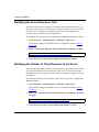
Modifying the Client’s IP Address ...................................................................................3-1
Modifying Service from Authentication to Accounting ....................................................3-2
Modifying the Protocol for RADIUS Authentication .........................................................3-3
Modifying the PPP Authentication Protocol ....................................................................3-6
Removing RADIUS Authentication and Accounting .......................................................3-8
Chapter 4
Customizing the RADIUS Server Configuration
Modifying the Primary Server’s Password ......................................................................4-1
Modifying the Server Mode .............................................................................................4-3
Authentication and Accounting UDP Ports .....................................................................4-3
Modifying the Server Response Time ............................................................................4-4
Modifying the Number of Client Requests to the Server ................................................4-4
Configuring Alternate Servers ........................................................................................4-5
Reconnecting to the Primary Server ..............................................................................4-7
Changing the Primary and Alternate Servers .................................................................4-7
Removing a Server Entry ...............................................................................................4-8
Appendix A
RADIUS Parameters
Client IP Address Parameter ......................................................................................... A-1
Server Configuration Parameters .................................................................................. A-2
Protocol Parameters for RADIUS Authentication ........................................................... A-5
Appendix B
RADIUS Parameter Defaults
Appendix C
Configuration Examples
Configuring RADIUS Authentication .............................................................................. C-2
Before You Begin ..................................................................................................... C-2
Enable RADIUS Authentication ............................................................................... C-3
Select IP .................................................................................................................. C-4
Configuring RADIUS Accounting ................................................................................... C-5
Before You Begin ..................................................................................................... C-6
Create a Backup Pool ............................................................................................. C-6
vi
303538-A Rev 00
Create a Dial Backup Circuit ................................................................................... C-7
Enable RADIUS Accounting .................................................................................... C-8
Configuring RADIUS Accounting and Authentication .................................................... C-9
Before You Begin ................................................................................................... C-10
Enable Dial Backup Service .................................................................................. C-10
Enable RADIUS Accounting and Authentication ................................................... C-10
Select IP for RADIUS Authentication .............................................................. C-11
Index
303538-A Rev 00
vii
Figures
Figure 1-1.
Configuration Manager Window ...............................................................1-3
Figure 1-2.
RADIUS Client Configuration Window .....................................................1-4
Figure 1-3.
RADIUS Menu .........................................................................................1-4
Figure 1-4.
Choose WAN Serial Interface Type Window ............................................1-5
Figure 1-5.
Sync Line Media Type Window ................................................................1-6
Figure 1-6.
Async Line Media Type Window ..............................................................1-6
Figure 1-7.
ISDN Switch Configuration Window .........................................................1-7
Figure 1-8.
ISDN Logical Lines Window .....................................................................1-7
Figure 1-9.
Primary Server Address Window .............................................................1-9
Figure 1-10. RADIUS Server Configuration Window ..................................................1-10
Figure 1-11. RADIUS Dial_In Slot Window ................................................................1-11
Figure 1-12. RADIUS Dial_In Protocol Window .........................................................1-12
Figure 1-13. Dial Optimized Routing Query Window ..................................................1-12
Figure 2-1.
Sample Network Using RADIUS ..............................................................2-2
Figure 3-1.
RADIUS Client Configuration Window .....................................................3-1
Figure 3-2.
RADIUS Dial_In Slot Window ..................................................................3-3
Figure 3-3.
RADIUS Dial_In Protocol Window ...........................................................3-4
Figure 3-4.
Dial Optimized Routing Query Window ....................................................3-4
Figure 3-5.
PPP Interface List Window ......................................................................3-6
Figure 3-6.
PPP Line Lists Window ............................................................................3-7
Figure 4-1.
RADIUS Server Configuration Window ....................................................4-2
Figure 4-2.
RADIUS Server Configuration Window ....................................................4-5
Figure 4-3.
Alternate Server Address Window ...........................................................4-6
Figure C-1.
Sample Network Using RADIUS Authentication ..................................... C-2
Figure C-2.
Sample Network Using RADIUS Accounting .......................................... C-5
Figure C-3.
Sample Network Configured for Dialing an Alternate Site ...................... C-9
303538-A Rev 00
ix
Tables
Table B-1.
303538-A Rev 00
RADIUS Parameter Defaults ................................................................... B-1
xi
Preface
This guide describes Remote Authentication Dial-In User Service (RADIUS) and
what you do to start and customize RADIUS on a Bay Networks® router.
Before You Begin
Before using this guide, you must complete the following procedures. For a new
router:
•
Install the router (refer to the installation manual that came with your router).
•
Connect the router to the network and create a pilot configuration file (refer to
Quick-Starting Routers, Configuring BayStack Remote Access, or Connecting
ASN Routers to a Network).
Make sure that you are running the latest version of Bay Networks BayRS™ and
Site Manager software. For information about upgrading BayRS and Site
Manager, see the upgrading guide for your version of BayRS.
303538-A Rev 00
xiii
Configuring RADIUS
Text Conventions
This guide uses the following text conventions:
bold text
Indicates text that you need to enter and command
names and options.
Example: Enter show ip {alerts | routes}
Example: Use the dinfo command.
italic text
Indicates file and directory names, new terms, book
titles, and variables in command syntax descriptions.
Where a variable is two or more words, the words are
connected by an underscore.
Example: If the command syntax is:
show at <valid_route>
valid_route is one variable and you substitute one value
for it.
separator ( > )
Shows menu paths.
Example: Protocols > IP identifies the IP option on the
Protocols menu.
vertical line ( | )
Separates choices for command keywords and
arguments. Enter only one of the choices. Do not type
the vertical line when entering the command.
Example: If the command syntax is:
show ip {alerts | routes}, you enter either:
show ip alerts or show ip routes, but not both.
xiv
303538-A Rev 00
Preface
Acronyms
303538-A Rev 00
CHAP
Challenge Handshake Authentication Protocol
IP
Internet Protocol
IPX
Internet Packet Exchange
IPXWAN
Internet Packet Exchange Wide Area Network
ISDN
Integrated Services Digital Network
ISP
Internet service provider
ITU-T
International Telecommunication
Union–Telecommunications (formerly CCITT)
LAN
local area network
OSPF
Open Shortest Path First (protocol)
PAP
Password Authentication Protocol
POTS
plain old telephone service
PPP
Point-to-Point Protocol
RADIUS
Remote Authentication Dial-In User Service
RIP
Routing Information Protocol
SAP
Service Advertising Protocol
TCP/IP
Transmission Control Protocol/Internet Protocol
UDP
User Datagram Protocol
WAN
wide area network
xv
Configuring RADIUS
Bay Networks Technical Publications
You can now print Bay Networks technical manuals and release notes free,
directly from the Internet. Go to support.baynetworks.com/library/tpubs/. Find the
Bay Networks product for which you need documentation. Then locate the
specific category and model or version for your hardware or software product.
Using Adobe Acrobat Reader, you can open the manuals and release notes, search
for the sections you need, and print them on most standard printers. You can
download Acrobat Reader free from the Adobe Systems Web site,
www.adobe.com.
You can purchase Bay Networks documentation sets, CDs, and selected technical
publications through the Bay Networks Collateral Catalog. The catalog is located
on the World Wide Web at support.baynetworks.com/catalog.html and is divided
into sections arranged alphabetically:
•
The “CD ROMs” section lists available CDs.
•
The “Guides/Books” section lists books on technical topics.
•
The “Technical Manuals” section lists available printed documentation sets.
Make a note of the part numbers and prices of the items that you want to order.
Use the “Marketing Collateral Catalog description” link to place an order and to
print the order form.
How to Get Help
For product assistance, support contracts, or information about educational
services, go to the following URL:
http://www.baynetworks.com/corporate/contacts/
Or telephone the Bay Networks Technical Solutions Center at:
800-2LANWAN
xvi
303538-A Rev 00
Chapter 1
Starting RADIUS
Remote Authentication Dial-In User Service (RADIUS) defines a method of
centralizing authentication and accounting information for networks with many
remote dial-in users. By placing authentication and accounting functions in one
central location, you can improve security and better manage large networks.
In a network using RADIUS, the router is the RADIUS client. The client is the
connection point between remote users and a RADIUS server. The server has the
information that it needs to identify remote users and to keep accounting
information for each call.
How to Use This Manual
Understanding how this manual is organized should make it more useful to you.
The manual is organized as follows:
•
Starting RADIUS
Begin by reading this chapter, which explains how to enable RADIUS on your
router using a basic configuration, that is, a configuration that uses all of the
available parameter defaults.
•
RADIUS overview
Provides information about RADIUS authentication and accounting and the
Bay Networks implementation of these services. This information is in
Chapter 2.
•
Instructions for modifying the default configuration introduced in Chapter 1
These instructions are in Chapters 3 and 4. Most of the instructions assume
that you have read Chapter 1 and explain how to modify the default
configuration.
303538-A Rev 00
1-1
Configuring RADIUS
The steps that instruct you to set a parameter value are followed by a box that
includes the Site Manager parameter and the location of the parameter
description in Appendix A. To read more about the parameter before setting a
value, refer to the specified page. You can also read these parameter
descriptions by clicking on Help in the Site Manager windows.
•
Parameter descriptions, parameter default tables, and configuration examples
This information is in Appendixes A through C.
Before You Begin
Before you enable RADIUS, do the following:
1.
Create and save a configuration file that has at least one wide area network
(WAN) interface.
2.
Retrieve the configuration file in local, remote, or dynamic mode.
3.
Specify the router hardware if this is a local-mode configuration.
4.
Configure the physical interface for any ISDN lines that you will use for
RADIUS.
Refer to Configuring Dial Services to learn how to configure ISDN lines.
5.
Configure one or more dial services so the RADIUS client can accept calls
from the remote user (RADIUS accounting only).
Configure dial-on-demand, dial backup, or bandwidth-on-demand service to
operate with RADIUS accounting. Refer to Configuring Dial Services for
instructions. Once you enable RADIUS authentication, the RADIUS client
automatically configures a dial connection; therefore, you are not required to
configure a dial service.
6.
Enable dial optimized routing on the remote routers (RADIUS authentication
only).
Dial optimized routing prevents Routing Information Protocol (RIP) updates
or Service Advertising Protocol (SAP) updates from keeping a line active
unnecessarily, thereby reducing the line costs. Enabling this feature improves
the operation of RADIUS authentication.
1-2
303538-A Rev 00
Starting RADIUS
Enabling RADIUS
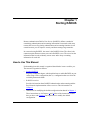
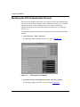
To enable RADIUS accounting or authentication, begin at the Configuration
Manager window:
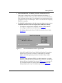
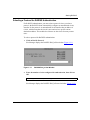
1.
Figure 1-1.
Select Protocols > Global Protocols > RADIUS > Create RADIUS
(Figure 1-1).
Configuration Manager Window
Site Manager displays the RADIUS Client Configuration window
(Figure 1-2), which shows the router slots available for configuring RADIUS.
303538-A Rev 00
1-3
Configuring RADIUS
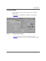
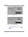
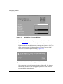
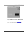
Figure 1-2.
RADIUS Client Configuration Window
The RADIUS Client Configuration Window for an ASN router looks different
than the window for the Backbone Link Node (BLN®) and Backbone
Concentrator Node (BCN®) routers (Figure 1-2), but it functions the same.
2.
To configure a slot for RADIUS, click on the box labeled None.
Site Manager displays a menu showing the RADIUS options (Figure 1-3).
Figure 1-3.
1-4
RADIUS Menu
303538-A Rev 00
Starting RADIUS
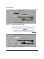
3.
Select Authentication, Accounting, or Both to enable both services.
If the router is already using a slot for dial-on-demand, dial backup, or
bandwidth-on-demand service, you cannot select this slot for authentication.
This restriction does not apply if you configured a slot with a demand circuit
group that uses only one demand pool. There is no restriction for configuring
RADIUS accounting.
4.
For RADIUS authentication, select the connectors that you want to serve
as RADIUS interfaces. This is not required for RADIUS accounting.
•
To configure a modem line for RADIUS, click on a COM connector.
(To configure an ISDN line for RADIUS, go to page 1-7.)
Site Manager displays the Choose WAN Serial Interface Type window
(Figure 1-4).
Figure 1-4.
Choose WAN Serial Interface Type Window
On the BLN and BCN, the Choose WAN Serial Interface Type window
appears only for ports on an Octal Sync Link Module. For all other
modules, Site Manager displays the Sync Line Media Type window
(Figure 1-5).
If you are using synchronous PPP for your dial connections, accept the
default, Sync, for the WAN Serial Interface Type parameter. Site Manager
displays the Sync Line Media Type window (Figure 1-5). If you plan to
use Asynchronous PPP for your dial connections, select Async. Site
Manager displays the Async Line Media Type window (Figure 1-6).
303538-A Rev 00
1-5
Configuring RADIUS
Figure 1-5.
Sync Line Media Type Window
Figure 1-6.
Async Line Media Type Window
Click on OK to accept the line media type defaults.
You return to the RADIUS Client Configuration window (refer to
Figure 1-2). Go to Step 5.
1-6
303538-A Rev 00
Starting RADIUS
•
To configure an ISDN line for RADIUS, click on an ISDN, MCT1, or
MCE1 connector.
Site Manager displays the ISDN Switch Configuration window
(Figure 1-7).
Figure 1-7.
ISDN Switch Configuration Window
Click on OK to accept the defaults. Site Manager displays the ISDN
Logical Lines window (Figure 1-8).
Figure 1-8.
ISDN Logical Lines Window
Click on OK to accept the defaults.
You return to the RADIUS Client Configuration window (refer to
Figure 1-2).
303538-A Rev 00
1-7
Configuring RADIUS
Site Manager adds the letters DR to the connector’s name to designate it
as a RADIUS interface.
5.
Keep the RADIUS Client Configuration window open and go to the next
section, “Specifying the Client’s IP Address.”
Specifying the Client’s IP Address
To enable RADIUS, you must specify the client’s Internet Protocol (IP) address.
As the RADIUS client, the router passes this address to the server when a remote
user makes an authentication or accounting request. The server does not accept the
request without the client’s IP address.
To configure the client’s IP address:
1.
Enter an IP address for the Client IP Address parameter.
Site Manager: Client IP Address parameter: page A-1
2.
1-8
Keep the RADIUS Client Configuration window open and go to the next
section, “Specifying the Primary Server’s IP Address.”
303538-A Rev 00
Starting RADIUS
Specifying the Primary Server’s IP Address
To enable RADIUS, you must specify the IP address of the RADIUS server. The
first server you configure is the primary server. You can have only one primary
server for each client.
To configure the primary server’s IP address:
1.
Click on Server.
Site Manager displays the Primary Server Address window (Figure 1-9).
Figure 1-9.
2.
Primary Server Address Window
Enter the IP address of the RADIUS server.
Site Manager: Server IP Address parameter: page A-2
3.
Enter a password for the server.
Site Manager: RADIUS Password parameter: page A-2
The client and server must use the same password.
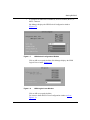
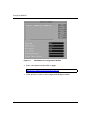
4.
Click on OK.
Site Manager displays the RADIUS Server Configuration window, which
shows the parameter defaults for the server (Figure 1-10).
303538-A Rev 00
1-9
Configuring RADIUS
Figure 1-10.
5.
RADIUS Server Configuration Window
Click on Done to accept the parameter defaults.
You return to the RADIUS Client Configuration window (refer to Figure 1-2).
6.
1-10
Keep the RADIUS Client Configuration window open and go to the next
section, “Selecting a Protocol for RADIUS Authentication.”
303538-A Rev 00
Starting RADIUS
Selecting a Protocol for RADIUS Authentication
For RADIUS authentication, you must select a protocol. Once you select a
protocol, the RADIUS client automatically configures an unnumbered circuit
interface for the protocol. An unnumbered circuit interface has an address of
0.0.0.0, which means that the circuit is not restricted to a specific remote
destination address. This enables the client to use the circuit for many remote
users.
To select a protocol for RADIUS authentication:
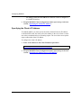
1.
Click on Dial-In Protocol.
Site Manager displays the RADIUS Dial_In Slot window (Figure 1-11).
Figure 1-11.
2.
RADIUS Dial_In Slot Window
Enter the number of a slot configured for authentication, then click on
OK.
Site Manager: Slot Number parameter: page A-5
Site Manager displays the RADIUS Dial_In Protocol window (Figure 1-12).
303538-A Rev 00
1-11
Configuring RADIUS
Figure 1-12.
3.
RADIUS Dial_In Protocol Window
Select Enable for the protocol you want to use, then click on OK.
Refer to Appendix A for parameter descriptions of each protocol.
If your network uses only dial-up lines, we recommend that you enable IP
together with RIP or the Internet Packet Exchange (IPX) protocol. When you
enable these parameters, Site Manager displays a window that asks if the
remote site is using dial optimized routing (Figure 1-13).
Figure 1-13.
Dial Optimized Routing Query Window
If the remote site is using dial optimized routing, click on OK. Site Manager
automatically modifies several routing update parameters so the client can
operate with dial optimized routing.
1-12
303538-A Rev 00
Starting RADIUS
If your network uses a combination of leased lines and dial-up lines (for
example, using dial backup service to support leased connections), it is
unlikely that the routers use dial optimized routing, so click on Cancel. Site
Manager will not modify the routing update parameters.
After you respond to the window, you return to the RADIUS Dial_In Protocol
window.
4.
Click on OK.
You return to the RADIUS Client Configuration window (refer to Figure 1-2).
5.
303538-A Rev 00
Click on Done to return to the Configuration Manager window.
1-13
Chapter 2
RADIUS Overview
Remote access is a rapidly growing segment of the networking industry. Users in
branch offices, sales people in the field, and telecommuters are just a few of the
people who rely on remote access to do their jobs. Internet service providers
(ISPs) want to offer more remote-access services to their customers and control
the billing of those services. As networks grow to accommodate more users,
network security and billing become more difficult to manage.
RADIUS solves these issues by centralizing security and accounting information.
This improves security and provides a solution that can adapt to the changing size
and needs of remote users and service providers.
How RADIUS Works
A RADIUS application has two components, the RADIUS server and the
RADIUS client.
The RADIUS server is a computer equipped with server software (for example, a
UNIX workstation) that is located at a central office or campus. It has
authentication and access information in a form that is compatible with the client.
A network can have one server for both authentication and accounting, or one
server for each service.
The RADIUS client can be a router or a remote-access server that is equipped
with client software and typically resides on the same local area network (LAN)
segment as the server. The client is the network access point between the remote
users and the server.
303538-A Rev 00
2-1
Configuring RADIUS
RADIUS authentication lets you identify remote users before you give them
access to a central network site. RADIUS accounting enables the server to collect
data during a remote user’s dial-in session with the client. The server can then
determine billing charges.
M
O
DE
M
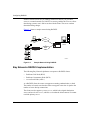
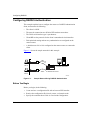
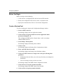
Figure 2-1 shows a sample network using RADIUS.
POTS
Remote dial-in
user
BLN
ISDN
RADIUS
server
RADIUS client
Remote dial-in
user
CR0001A
Figure 2-1.
Sample Network Using RADIUS
Bay Networks RADIUS Implementation
The following Bay Networks platforms can operate as RADIUS clients:
•
Backbone Link Node (BLN)
•
Backbone Concentrator Node (BCN)
•
Access Stack Node (ASN ™)
As a RADIUS client, the router can support accounting, authentication, or both.
The number of remote users that the client can support at one time is equal to the
number of active dial-up connections.
The client can also support a primary server, which is the original destination
server, and an alternate server, which is a server that the client contacts if it cannot
reach the primary server.
2-2
303538-A Rev 00
RADIUS Overview
RADIUS Authentication
You configure RADIUS authentication on a slot-by-slot basis. Therefore, a call
designated for a RADIUS-configured slot performs authentication. If the router is
already using a slot for dial-on-demand, dial backup, or bandwidth-on-demand
service, you cannot configure this slot for authentication. This restriction does not
apply if the slot is configured with a demand circuit group that uses only one
demand pool. In this case, you can configure authentication.
When a remote user calls the RADIUS client, the client passes the call request,
referred to as the access challenge, to the RADIUS server. The access challenge
contains the user’s name and password. The server verifies the user’s identity and,
for authorized callers, responds with an access accept message, which includes
the required access information. This information is sent to the client, which
passes it to the remote user. If the remote user is not authorized, the server
responds with an access reject message.
The client can pass multiple requests to the server simultaneously. If the client
cannot reach the server, and you configured an alternate server, the client passes
the request to the alternate server.
The authentication process occurs only once for each call. Once RADIUS
authentication is complete, the remote user can communicate with the destination
network.
Using PPP for Dial-up Connections
The Bay Networks RADIUS client uses Point-to-Point Protocol (PPP) for the
dial-up line between itself and the remote user. When you configure RADIUS,
Site Manager automatically configures PPP for the client.
To identify itself to the server, the remote user uses the PPP Challenge Handshake
Authentication Protocol (CHAP) or Password Authentication Protocol (PAP). The
client includes the remote user’s CHAP name and secret or PAP ID and password
in the access challenge to the server.
303538-A Rev 00
2-3
Configuring RADIUS
Using IP and IPX Unnumbered Protocols for PPP Connections
The RADIUS client supports only IP and IPX unnumbered interfaces, which
means that the circuit’s interface address is 0.0.0.0. All remote users that dial in to
the same slot on the client receive the same unnumbered protocol configuration.
Note: Unlike the circuit’s address, the RADIUS client’s address is a numbered
address.
The unnumbered circuit interface eliminates the need for a unique circuit
configuration for each remote user in a network. Therefore, an unnumbered circuit
interface reduces the configuration effort and the number of IP addresses that you
use for a large network. The client can activate any available circuit for an
incoming call because there is no specific address assigned to the circuit.
When you configure authentication for a router slot, Site Manager automatically
configures the dial-up circuits required for the client to accept calls from the
remote user. You are responsible for configuring only the unnumbered circuit
interfaces.
In addition to configuring unnumbered circuit interfaces, we recommend that you
enable IP or IPX triggered updates for the RADIUS client. The client uses
triggered updates to provide its local area network (LAN) with routing
information from the remote router. Refer to Configuring IP Services or
Configuring IPX Services for more information about triggered updates.
2-4
303538-A Rev 00
RADIUS Overview
Configuring the Remote User to Work with the RADIUS Client
In most RADIUS networks, the remote user is a router. To enable the remote
router to work with the RADIUS authentication client, follow these guidelines:
•
Enable dial optimized routing.
The remote router sends routing updates to advertise its LAN to the client. By
enabling dial optimized routing, you reduce the frequency of routing updates,
which prevents the line from remaining active unnecessarily.
•
Configure one-way PPP authentication.
The remote router must support one-way PPP authentication, which means
that only the client sends CHAP challenges or PAP authentication requests to
the remote user. The remote user only recognizes and responds to the CHAP
challenges or PAP authentication requests from the client.
•
Configure a default route in the routing table of the remote router.
The client does not advertise its LAN to the remote router. To specify the path
from the remote router to the client, you configure a default route, which is a
static route that enables the remote router to contact the client.
Refer to Appendix C for configuration examples.
303538-A Rev 00
2-5
Configuring RADIUS
RADIUS Accounting
You configure RADIUS accounting on a slot-by-slot basis. Therefore, a call
designated for a RADIUS-configured slot performs RADIUS accounting.
The RADIUS accounting server calculates billing charges for a communication
session between the remote user and the client. The RADIUS client sends
information to the server, such as the status of each call and the number of packets
transmitted during the session. Using this data, the server determines billing
charges, which the network administrator can use to manage network costs.
An accounting session is the time during which the remote user communicates
with the client. The session begins when the client passes an accounting request
from the remote user to the server, with an accounting status byte set to start. The
session ends when the client sends a second request with the accounting status
byte set to stop. Multiple accounting sessions can occur simultaneously if there
are multiple dial-up connections.
The client sends accounting requests only to the server configured for accounting,
which enables you to use different servers for accounting and authentication.
If the client cannot reach the primary server after several attempts, and you
configured an alternate server, the client sends the accounting request to the
alternate server. If an accounting session starts with the primary server, and this
server goes down, the session is continued with the alternate server. Unless the
primary server recovers, the request to end the session is then sent to the alternate
server. To accurately determine billing charges, the network administrator collects
information from all accounting servers.
Using PPP for Dial-up Connections
The Bay Networks client uses PPP for the dial-up line between itself and the
remote user. When you configure RADIUS, Site Manager automatically
configures PPP for the client.
Configuring a Dial Service for RADIUS Accounting
To use RADIUS accounting on the router, you must configure at least one of the
three Bay Networks dial services: dial-on-demand, dial backup, or
bandwidth-on-demand. The dial service enables the router to activate a dial-up
connection when it receives an incoming call. For information about dial services,
refer to Configuring Dial Services.
2-6
303538-A Rev 00
RADIUS Overview
Using RADIUS-Compatible Servers with the RADIUS Client
The Bay Networks RADIUS client can communicate with any
RADIUS-compatible server. You must configure the server’s IP address so that
the client can communicate with the server.
To ensure that a server is always available, you can configure one primary server
and multiple alternate servers. The client tries to connect to the primary server
first. If the primary server does not respond after a certain number of attempts, the
client sends the authentication or accounting request to the alternate server. Once
the primary server recovers, the client resumes communication with the primary
server.
Accepting Remote Users’ IP Addresses
The client accepts the IP address of a remote user only if the remote user is a PC,
not another router. The client does not support any other RADIUS extensions.
303538-A Rev 00
2-7
Configuring RADIUS
For More Information
Refer to the following sources for more information about RADIUS:
Aboba, B., Zorn, G. “RADIUS Client MIB.” Internet Draft. March 1997.
Aboba, B., Zorn, G. “RADIUS Server MIB.” Internet Draft. March 1997.
Aboba, B., Zorn, G. “Implementation of Mandatory Tunneling via RADIUS.”
Internet Draft. March 1997.
Internet Engineering Task Force World Wide Web site: http://ftp.ietf.org/.
Rigney, C. “RADIUS Accounting.” RFC 2139. April 1997.
Rigney, C., Rubens A., Simpson, W.A., Willens, S. “Remote Authentication Dial
In User Service (RADIUS).” RFC 2138. April 1997.
Rigney, C., Willats, W. “RADIUS Extensions.” Internet Draft. January 1997.
Zorn, G. “RADIUS Attributes for Tunnel Protocol Support.” Internet Draft.
March 1997.
Zorn, G. “Extensible RADIUS Attributes for Tunnel Protocol Support.”
Internet Draft. March 1997
2-8
303538-A Rev 00
Chapter 3
Customizing the RADIUS Client Configuration
This chapter describes the changes you can make to the RADIUS client’s
configuration.
Modifying the Client’s IP Address
You should have already configured an IP address for the client in Chapter 1.
To modify the address of the client, begin at the Configuration Manager window:
1.
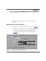
Select Protocols > Global Protocols > RADIUS > Edit RADIUS.
Site Manager displays the RADIUS Client Configuration window
(Figure 3-1).
Figure 3-1.
303538-A Rev 00
RADIUS Client Configuration Window
3-1
Configuring RADIUS
2.
Enter a new IP address for the Client IP Address parameter.
Site Manager: Client IP Address parameter: page A-1
3.
Click on Done to return to the Configuration Manager window.
Modifying Service from Authentication to Accounting
You can change the service from RADIUS authentication to accounting without
having to remove authentication. You may also want to use both services. To
change from accounting to authentication, you must remove accounting service
from the slot and then configure authentication service.
To modify service, begin at the Configuration Manager window:
1.
Select Protocols > Global Protocols > RADIUS > Edit RADIUS.
Site Manager displays the RADIUS Client Configuration window (refer to
Figure 3-1). This window shows the slots and their current configuration.
2.
Click on the box labeled Authentication, then select Accounting or Both.
The service you select is now operating for that slot.
3-2
3.
If necessary, modify the client and server addresses and protocol
configurations to accommodate the new service.
4.
Click on Done to return to the Configuration Manager window.
303538-A Rev 00
Customizing the RADIUS Client Configuration
Modifying the Protocol for RADIUS Authentication
To modify the unnumbered protocol for RADIUS authentication, begin at the
Configuration Manager window:
1.
Select Protocols > Global Protocols > RADIUS > Edit RADIUS.
Site Manager displays the RADIUS Client Configuration window (refer to
Figure 3-1).
2.
Click on Dial-In Protocol.
Site Manager displays the RADIUS Dial_In Slot window (Figure 3-2).
Figure 3-2.
3.
RADIUS Dial_In Slot Window
Enter the number of a slot configured for RADIUS, then click on OK.
Site Manager: Slot Number parameter: page A-5
Site Manager displays the RADIUS Dial_In Protocol window (Figure 3-3).
303538-A Rev 00
3-3
Configuring RADIUS
Figure 3-3.
4.
RADIUS Dial_In Protocol Window
Set the enabled protocol to Disable, and set the protocol you want to use
to Enable.
Refer to Appendix A for parameter descriptions of each protocol.
If your network uses only dial-up lines, we recommend that you enable IP
together with RIP or IPX. When you enable these parameters, Site Manager
displays a window that asks if the remote site is using dial optimized routing
(Figure 3-4).
Figure 3-4.
3-4
Dial Optimized Routing Query Window
303538-A Rev 00
Customizing the RADIUS Client Configuration
If the remote site is using dial optimized routing, click on OK. Site Manager
automatically modifies several routing update parameters so the client can
operate with dial optimized routing.
If your network uses a combination of leased lines and dial-up lines (for
example, using dial backup service to support leased connections), it is
unlikely that the routers use dial optimized routing, so click on Cancel. Site
Manager will not modify the routing update parameters.
After you respond to the window, you return to the RADIUS Dial_In Protocol
window.
5.
Click on OK.
You return to the RADIUS Client Configuration window (refer to Figure 3-1).
6.
303538-A Rev 00
Click on Done to return to the Configuration Manager window.
3-5
Configuring RADIUS
Modifying the PPP Authentication Protocol
The remote user identifies itself to the server using one of the PPP authentication
protocols, CHAP or PAP. It includes either a CHAP name and secret or a PAP ID
and password in the access challenge to the server. CHAP is the default
authentication protocol. For more information about PPP, refer to Configuring
PPP Services.
To change the authentication protocol to PAP, begin at the Configuration Manager
window:
1.
Select Protocols > PPP > Interfaces.
Site Manager displays the PPP Interface List window (Figure 3-5).
Figure 3-5.
2.
PPP Interface List Window
Select the Interface for Dialup Lines record, then click on Lines.
Site Manager displays the PPP Line Lists window (Figure 3-6).
3-6
303538-A Rev 00
Customizing the RADIUS Client Configuration
Figure 3-6.
PPP Line Lists Window
3.
Select PAPAUTH as the value for the Local Authentication Protocol
parameter.
4.
Click on Done.
You return to the PPP Interface List window (refer to Figure 3-5).
5.
303538-A Rev 00
Click on Done to return to the Configuration Manager window.
3-7
Configuring RADIUS
Removing RADIUS Authentication and Accounting
To remove RADIUS authentication and accounting from a slot, begin at the
Configuration Manager window:
1.
Select Protocols > Global Protocols > RADIUS > Edit RADIUS.
Site Manager displays the RADIUS Client Configuration window (refer to
Figure 3-1).
2.
Click on the box labeled Authentication, Accounting, or Both, then select
None.
Site Manager removes RADIUS from that slot.
3.
3-8
Click on Done to return to the Configuration Manager window.
303538-A Rev 00
Chapter 4
Customizing the RADIUS Server Configuration
This chapter explains how to modify the RADIUS server configuration. The
server parameters tell the client how the server is configured and define how the
client and server communicate.
Modifying the Primary Server’s Password
The first server you configure is the primary server. You can have only one
primary server for each client. You should have already entered the server’s IP
address in Chapter 1.
To modify the primary server’s password, begin at the Configuration Manager
window:
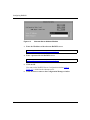
1.
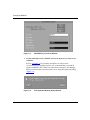
Select Protocols > Global Protocols > RADIUS > Edit Server.
Site Manager displays the RADIUS Server Configuration window, which
shows the parameter defaults for the server configuration (Figure 4-1).
303538-A Rev 00
4-1
Configuring RADIUS
Figure 4-1.
2.
RADIUS Server Configuration Window
Enter a new password, then click on Apply.
Site Manager: RADIUS Password parameter: page A-2
3.
4-2
Click on Done to return to the Configuration Manager window.
303538-A Rev 00
Customizing the RADIUS Server Configuration
Modifying the Server Mode
The server mode tells the client how the server is configured. You may want to
change the service from RADIUS authentication to accounting or from
accounting to authentication. You may also want to use both services.
To modify the server mode, begin at the Configuration Manager window:
1.
Select Protocols > Global Protocols > RADIUS > Edit Server.
Site Manager displays the RADIUS Server Configuration window (refer to
Figure 4-2).
2.
Enter a value for the Server Mode parameter, then click on Apply.
Site Manager: Server Mode parameter: page A-2
3.
Click on Done to return to the Configuration Manager window.
Authentication and Accounting UDP Ports
The User Datagram Protocol (UDP) port is the logical port that designates data for
the RADIUS application on the server. The UDP port is typically included in an
IP datagram.
The default values for the authentication and accounting UDP ports follow the
RADIUS RFC specifications. In general, you should not change these values.
Refer to Appendix A for parameter descriptions.
303538-A Rev 00
4-3
Configuring RADIUS
Modifying the Server Response Time
When the client sends an accounting or authentication request to the server, you
can specify how long the client waits for a response from the server. If the client
does not receive a response, it retransmits the request. This waiting period
prevents network operations from slowing down.
To modify the server response time, begin at the Configuration Manager window:
1.
Select Protocols > Global Protocols > RADIUS > Edit Server.
Site Manager displays the RADIUS Server Configuration window (refer to
Figure 4-2).
2.
Enter a value for the Response Timeout parameter, then click on Apply.
Site Manager: Response Timeout (seconds) parameter: page A-4
3.
Click on Done to return to the Configuration Manager window.
Modifying the Number of Client Requests to the Server
You can modify the number of times the client sends a request to the server before
the client considers the server unreachable. If the server is located at a distance
from the client, you may want to set the number of requests to a higher value than
the default.
To modify the number of client requests to the server, begin at the Configuration
Manager window:
1.
Select Protocols > Global Protocols > RADIUS > Edit Server.
Site Manager displays the RADIUS Server Configuration window (refer to
Figure 4-2).
2.
Enter a new value for the Maximum Message Retry parameter, then click
on Apply.
Site Manager: Maximum Message Retry parameter: page A-3
3.
4-4
Click on Done to return to the Configuration Manager window.
303538-A Rev 00
Customizing the RADIUS Server Configuration
Configuring Alternate Servers
In addition to the primary server, you can configure one or more alternate
RADIUS servers. An alternate server ensures that you can maintain network
security and accounting in case the primary server fails. You must configure a
primary server before you configure an alternate server. After that, you can
configure multiple alternate servers for each client.
To configure an alternate server, begin at the Configuration Manager window:
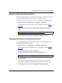
1.
Select Protocols > Global Protocols > RADIUS > Edit Server.
Site Manager displays the RADIUS Server Configuration window
(Figure 4-2).
Figure 4-2.
2.
RADIUS Server Configuration Window
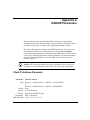
Click on Add Alt.
Site Manager displays the Alternate Server Address window (Figure 4-3).
303538-A Rev 00
4-5
Configuring RADIUS
Figure 4-3.
3.
Alternate Server Address Window
Enter the IP address of the alternate RADIUS server.
Site Manager: Server IP Address parameter: page A-2
4.
Enter a password for the RADIUS server.
Site Manager: RADIUS Password parameter: page A-2
5.
Click on OK.
You return to the RADIUS Server Configuration window (refer to
Figure 4-2), which lists the alternate server.
6.
4-6
Click on Done to return to the Configuration Manager window.
303538-A Rev 00
Customizing the RADIUS Server Configuration
Reconnecting to the Primary Server
If the primary server fails, you can instruct the client to use an alternate server, but
after a specified time period, try to reconnect to the primary server.
To reconnect to the primary server, begin at the Configuration Manager window:
1.
Select Protocols > Global Protocols > RADIUS > Edit Server.
Site Manager displays the RADIUS Server Configuration window (refer to
Figure 4-2).
2.
Enter a new value for the Server Reset Timer parameter, then click on
Apply.
Site Manager: Server Reset Timer (minutes) parameter: page A-4
3.
Click on Done to return to the Configuration Manager window.
Changing the Primary and Alternate Servers
You can change which server is the primary and which is the alternate. Begin at
the Configuration Manager window:
1.
Select Protocols > Global Protocols > RADIUS > Edit Server.
Site Manager displays the RADIUS Server Configuration window (refer to
Figure 4-2).
2.
Select an alternate server entry from the list.
3.
Set the Server Mode parameter to the appropriate service.
Site Manager: Server Mode parameter: page A-2
4.
Click on Primary.
Site Manager changes the entry in the list. The alternate server is now the
primary server, and the original primary server is now the alternate server.
5.
303538-A Rev 00
Click on Done to return to the Configuration Manager window.
4-7
Configuring RADIUS
Removing a Server Entry
To remove a server entry from the RADIUS configuration, begin at the
Configuration Manager window:
1.
Select Protocols > Global Protocols > RADIUS > Edit Server.
Site Manager displays the RADIUS Server Configuration window (refer to
Figure 4-2).
2.
Select a server entry, then click on Delete.
Site Manager removes the entry from the list.
3.
4-8
Click on Done to return to the Configuration Manager window.
303538-A Rev 00
Appendix A
RADIUS Parameters
This appendix describes each of the RADIUS parameters. Each description
includes the path of Site Manager windows that you follow to find the parameter.
Each path assumes that you begin at the Configuration Manager window.
You can use Site Manager to modify all RADIUS parameters. You can also use
the Technician Interface to modify parameters by issuing set and commit
commands with the Management Information Base (MIB) object ID. This process
is the same as modifying parameters using Site Manager. For information about
using the Technician Interface to access the MIB, refer to Using Technician
Interface Software.
Caution: The Technician Interface does not verify that the value you enter for
a parameter is valid. Entering an invalid value can corrupt your configuration.
Client IP Address Parameter
Parameter: Client IP Address
Path: Protocols > Global Protocols > RADIUS > Create RADIUS
or
Protocols > Global Protocols > RADIUS > Edit RADIUS
Default: None
Options: A 32-bit IP address
Function: Identifies the RADIUS client.
Instructions: Enter an IP address.
MIB Object ID: 1.3.6.1.4.1.18.3.5.22.1.1.5
303538-A Rev 00
A-1
Configuring RADIUS
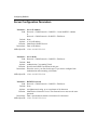
Server Configuration Parameters
Parameter: Server IP Address
Path: Protocols > Global Protocols > RADIUS > Create RADIUS > Server
or
Protocols > Global Protocols > RADIUS > Edit Server
Default: None
Options: A 32-bit IP address
Function: Identifies the RADIUS server.
Instructions: Enter an IP address.
MIB Object ID: 1.3.6.1.4.1.18.3.5.22.2.1.3
Parameter: Server Mode
Path:
Default:
Options:
Function:
Instructions:
Protocols > Global Protocols > RADIUS > Edit Server
Both
Authentication | Accounting | Both
Specifies the RADIUS operation for this port.
Select the service you want for this port. If you want to configure both
authentication and accounting, select Both.
MIB Object ID: 1.3.6.1.4.1.18.3.5.22.2.1.4
Parameter: RADIUS Password
Path:
Default:
Options:
Function:
Protocols > Global Protocols > RADIUS > Edit Server
None
An alphanumeric string, up to a maximum of 64 characters
Identifies the client to the server. The client and server must use the same
password.
Instructions: Enter a password that contains a maximum of 64 characters.
MIB Object ID: 1.3.6.1.4.1.18.3.5.22.2.1.11
A-2
303538-A Rev 00
RADIUS Parameters
Parameter: Auth. UDP Port
Path:
Default:
Options:
Function:
Protocols > Global Protocols > RADIUS > Edit Server
1645
An integer specifying the UDP logical port for authentication
Designates a data packet for RADIUS authentication. This number is required
for access to the authentication server.
Instructions: Accept the default.
MIB Object ID: 1.3.6.1.4.1.18.3.5.22.2.1.6
Parameter: Acct. UDP Port
Path:
Default:
Options:
Function:
Protocols > Global Protocols > RADIUS > Edit Server
1646
An integer specifying the UDP logical port for accounting
Designates a data packet for RADIUS accounting. This number is required for
access to the accounting server.
Instructions: Accept the default.
MIB Object ID: 1.3.6.1.4.1.18.3.5.22.2.1.9
Parameter: Maximum Message Retry
Path:
Default:
Options:
Function:
Protocols > Global Protocols > RADIUS > Edit Server
2
1 to 10
Specifies the number of times the RADIUS client retransmits a request before it
considers the RADIUS server unreachable.
Instructions: Enter the number of times you want the client to retransmit a request.
MIB Object ID: 1.3.6.1.4.1.18.3.5.22.2.1.13
303538-A Rev 00
A-3
Configuring RADIUS
Parameter: Response Timeout (seconds)
Path:
Default:
Options:
Function:
Protocols > Global Protocols > RADIUS > Edit Server
3
1 to 60
Specifies the number of seconds the RADIUS client waits before retransmitting
a request to the RADIUS server.
Instructions: Accept the default or enter a number of seconds in the range 1 to 60.
MIB Object ID: 1.3.6.1.4.1.18.3.5.22.2.1.12
Parameter: Server Reset Timer (minutes)
Path:
Default:
Options:
Function:
Protocols > Global Protocols > RADIUS > Edit Server
10
1 to 60
Specifies the number of minutes the RADIUS client waits before retrying the
primary server after it fails to respond. If the primary server fails to respond, the
client considers it unreachable and switches to the alternate server. After this
specified time period, the client tries to reconnect to the primary server.
Instructions: Accept the default or enter the number of minutes you want the client to wait for
the primary server to recover.
MIB Object ID: 1.3.6.1.4.1.18.3.5.22.2.1.14
A-4
303538-A Rev 00
RADIUS Parameters
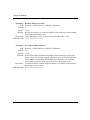
Protocol Parameters for RADIUS Authentication
These protocols are only for RADIUS authentication.
Parameter: Slot Number
Path: Protocols > Global Protocols > RADIUS > Edit RADIUS > Dial-In Protocol >
RADIUS Dial_In Slot
Default: None
Options: An integer that represents a router slot configured for RADIUS
Function: Identifies the slot configured for RADIUS.
Instructions: Enter the slot number.
MIB Object ID: 1.3.6.1.4.1.18.3.5.22.1.1.4
Parameter: IP Enable
Path: Protocols > Global Protocols > RADIUS > Edit RADIUS > Dial-In Protocol >
RADIUS Dial_In Slot > RADIUS Dial_In Protocol
Default: Disable
Options: Enable | Disable
Function: Enables or disables IP on this interface.
Instructions: Select Enable to enable IP on this interface.
MIB Object ID: 1.3.6.1.4.1.18.3.5.1.4.12.1.5
Parameter: RIP Enable
Path: Protocols > Global Protocols > RADIUS > Edit RADIUS > Dial-In Protocol >
RADIUS Dial_In Slot > RADIUS Dial_In Protocol
Default: Disable
Options: Enable | Disable
Function: Enables or disables RIP on this interface.
Instructions: Select Enable to enable RIP on this interface.
MIB Object ID: 1.3.6.1.4.1.18.3.5.1.4.12.1.7
303538-A Rev 00
A-5
Configuring RADIUS
Parameter: OSPF Enable
Path: Protocols > Global Protocols > RADIUS > Edit RADIUS > Dial-In Protocol >
RADIUS Dial_In Slot > RADIUS Dial_In Protocol
Default: Disable
Options: Enable | Disable
Function: Enables or disables OSPF on this interface.
Instructions: Select Enable to enable OSPF on this interface.
MIB Object ID: 1.3.6.1.4.1.18.3.5.1.4.12.1.8
Parameter: IPX Enable
Path: Protocols > Global Protocols > RADIUS > Edit RADIUS > Dial-In Protocol >
RADIUS Dial_In Slot > RADIUS Dial_In Protocol
Default: Disable
Options: Enable | Disable
Function: Enables or disables IPX on this interface.
Instructions: Select Enable to enable IPX on this interface.
MIB Object ID: 1.3.6.1.4.1.18.3.5.1.4.12.1.9
Parameter: IPXWAN Enable
Path: Protocols > Global Protocols > RADIUS > Edit RADIUS > Dial-In Protocol >
RADIUS Dial_In Slot > RADIUS Dial_In Protocol
Default: Disable
Options: Enable | Disable
Function: Enables or disables IPXWAN on this interface.
Instructions: Select Enable to enable IPXWAN on this interface.
MIB Object ID: 1.3.6.1.4.1.18.3.5.1.4.12.1.13
A-6
303538-A Rev 00
RADIUS Parameters
Parameter: Bridge Enable
Path: Protocols > Global Protocols > RADIUS > Edit RADIUS > Dial-In Protocol >
RADIUS Dial_In Slot > RADIUS Dial_In Protocol
Default: Disable
Options: Enable | Disable
Function: Enables or disables bridging on this interface.
Instructions: Select Enable to enable bridging on this interface.
MIB Object ID: 1.3.6.1.4.1.18.3.5.1.4.12.1.10
303538-A Rev 00
A-7
Appendix B
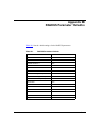
RADIUS Parameter Defaults
Table B-1 lists the default settings for the RADIUS parameters.
Table B-1.
303538-A Rev 00
RADIUS Parameter Defaults
Parameter
Default
Client IP Address
None
Server IP Address
None
RADIUS Password
None
Server Mode
Both
Auth. UDP Port
1645
Acct. UDP Port
1646
Maximum Message Retry
2
Response Timeout (seconds)
3
Server Reset Timer (minutes)
10
Slot Number
None
IP Enable
Disable
RIP Enable
Disable
OSPF Enable
Disable
IPX Enable
Disable
IPXWAN Enable
Disable
Bridge Enable
Disable
B-1
Appendix C
Configuration Examples
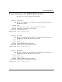
This appendix provides the following configuration examples for a router acting
as a RADIUS client:
•
Configuring RADIUS authentication
•
Configuring RADIUS accounting
•
Configuring RADIUS authentication and accounting
The examples show only those parameters whose defaults you must change for
proper configuration. The examples do not show any configuration windows. For
dial service windows, refer to Configuring Dial Services; for RADIUS windows,
refer to the appropriate chapter in this manual.
303538-A Rev 00
C-1
Configuring RADIUS
Configuring RADIUS Authentication
This example explains how to configure the router as a RADIUS authentication
client, and assumes the following:
•
The client is a BLN.
•
The network connections are all Raise DTR modem connections.
•
The WAN serial interface type is synchronous.
•
IP and RIP are the protocols for the client’s unnumbered circuit interface.
•
Dial optimized routing and one-way authentication are configured on the
remote routers.
•
A default route of 0.0.0.0 is configured on the remote routers to contact the
client.
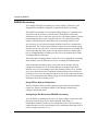
M
O
DE
M
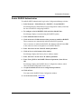
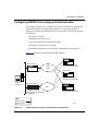
Figure C-1 shows the sample network for this example.
POTS
Remote
user A
M
O
DE
M
RADIUS server
IP address: 192.32.24.7
Remote
user B
POTS
RADIUS client
IP address:192.32.24.6
CR0002A
Figure C-1.
Sample Network Using RADIUS Authentication
Before You Begin
Before you begin, do the following:
C-2
1.
Create and save a configuration file with at least one PPP interface.
2.
Retrieve the configuration file in local, remote, or dynamic mode.
3.
Specify the router hardware if this is a local-mode configuration.
303538-A Rev 00
Configuration Examples
Enable RADIUS Authentication
To enable RADIUS authentication, begin at the Configuration Manager window:
1.
Select Protocols > Global Protocols > RADIUS > Create RADIUS.
Site Manager displays the RADIUS Client Configuration window, which lists
the slots available for configuring RADIUS.
2.
To configure a slot for RADIUS, click on the box labeled None.
Site Manager displays a menu showing the RADIUS options.
3.
Select Authentication for the slot.
4.
Click on the slot’s COM connectors that you want to enable for RADIUS.
These connectors are automatically enabled for RADIUS operation.
Once a connector is enabled for RADIUS, Site Manager adds the letters DR
to the connector’s name to designate it as a RADIUS interface.
5.
Enter 192.32.24.6 for the Client IP Address parameter.
6.
Click on Server at the bottom of the window.
Site Manager displays the Primary Server Address window.
7.
Enter 192.32.24.7 for the Server IP Address parameter.
8.
Enter Client_BLN for the RADIUS Password parameter, then click on
OK.
Site Manager displays the RADIUS Server Configuration window, which
shows the default configuration for the server.
9.
Accept the defaults for the server configuration parameters.
10. Click on Done.
You return to the RADIUS Client Configuration window.
11. Go to the next section, “Select IP.”
303538-A Rev 00
C-3
Configuring RADIUS
Select IP
From the RADIUS Client Configuration window:
1.
Click on Dial-In Protocol.
Site Manager displays the RADIUS Dial_In Slot window.
2.
Enter the number of the slot configured for RADIUS, then click on OK.
Site Manager displays the RADIUS Dial_In Protocol window.
3.
Select Enable for the IP Enable parameter.
4.
Select Enable for the RIP Enable parameter.
5.
Click on OK.
Site Manager displays a window that asks if the remote site is using dial
optimized routing. The remote routers in this example are using dial
optimized routing.
6.
Click on OK.
Site Manager modifies the values of several routing update parameters;
however, these changes are transparent to you.
You return to the RADIUS Client Configuration window.
7.
C-4
Click on Done to return to the Configuration Manager window.
303538-A Rev 00
Configuration Examples
Configuring RADIUS Accounting
This example explains how to configure the router as a RADIUS accounting
client, and assumes the following:
•
The client is an ASN.
•
Dial backup is the dial service.
•
The RADIUS client only receives calls, it does not make calls; therefore, you
do not need to configure an outgoing phone list and local CHAP name and
secret for the client.
•
The leased and dial backup connections are using PPP.
•
The WAN serial interface type is synchronous.
•
RADIUS authentication is not configured on the client.
Figure C-2 shows the sample network for this example.
Site A
ISDN
Remote users
RADIUS server
IP address: 192.32.24.3
Site B
ISDN
RADIUS client
IP address: 192.32.24.2
Remote users
Key
Primary line
Backup line
Figure C-2.
303538-A Rev 00
CR0003A
Sample Network Using RADIUS Accounting
C-5
Configuring RADIUS
Before You Begin
Before you begin, do the following:
1.
Create and save a configuration file with at least one PPP interface.
2.
Retrieve the configuration file in local, remote, or dynamic mode.
3.
Specify the router hardware if this is a local-mode configuration.
Create a Backup Pool
To create a backup pool, begin at the Configuration Manager window:
1.
Select an ISDN connector.
Site Manager displays the Port Application window.
2.
Click on OK to accept the default for the Port Application Mode
parameter, Dialup 2B + D.
This configures the BRI interface. Repeat Steps 1 and 2 to configure
additional BRI interfaces.
3.
Select Dialup > Backup Pools.
Site Manager displays the Backup Pools window.
4.
Click on Add.
Site Manager displays the Backup Pools Configuration window.
5.
Enter a pool ID, then click on OK.
Site Manager displays the Backup Lines Definition window.
6.
Click on an ISDN connector to assign a line to the pool, following these
guidelines:
•
Site Manager does not allow you to select any lines that you configured as
leased lines.
•
Lines in a backup pool may reside across slots.
Site Manager displays the ISDN Switch Configuration window.
7.
Click on Done to accept the parameter defaults.
Site Manager displays the ISDN Logical Lines window.
8.
C-6
Click on OK to accept the parameter defaults.
303538-A Rev 00
Configuration Examples
You return to the Backup Lines Definition window. The letter B (backup)
appears next to the ISDN port to indicate that it is a backup line.
9.
Select File > Exit to exit the Backup Lines Definition window.
You return to the Backup Pools window, which has three new buttons (Edit,
Apply, and Delete) that allow you to edit the new pool.
10. Repeat Steps 3 through 9 to select additional lines for the pool.
11. Click on Done to return to the Configuration Manager window.
Create a Dial Backup Circuit
To create a PPP backup circuit, begin at the Configuration Manager window:
1.
Select Backup Circuits > PPP.
Site Manager displays the Primary Circuit Definition window, which lists the
leased circuits that you have configured.
2.
Select a circuit entry and click on Cct Type.
Site Manager displays the Circuit Options window.
3.
Enter Primary for the Circuit Type parameter.
4.
Enter the ID of the backup pool that this circuit should use.
5.
Click on OK.
You return to the Primary Circuit Definition window, which shows the
parameter defaults supplied by Site Manager.
6.
Repeat Steps 2 through 5 to specify additional primary circuits.
7.
Scroll down the Primary Circuit Definition window to the Backup Mode
parameter.
8.
Select a value for the Backup Mode parameter. The default is Master.
If this router is the master router, the peer router’s backup mode must be set to
Slave. If you set the backup mode to Slave, Site Manager prompts you for
caller resolution information so the slave router can verify the identity of a
remote caller.
Refer to Configuring Dial Services for more information about dial backup
circuits.
303538-A Rev 00
C-7
Configuring RADIUS
Enable RADIUS Accounting
To enable RADIUS accounting, begin at the Configuration Manager window:
1.
Select Protocols > Global Protocols > RADIUS > Create RADIUS.
Site Manager displays the RADIUS Client Configuration window.
2.
To configure a slot for RADIUS, click on the box labeled None.
Site Manager displays a menu showing the RADIUS options.
3.
Select Accounting for the slot.
4.
Enter 192.32.24.2 for the Client IP Address parameter.
5.
Click on Server at the bottom of the window.
Site Manager displays the Primary Server Address window.
6.
Enter 192.32.24.3 for the Server IP Address parameter.
7.
Enter Client_ASN for the RADIUS Password parameter, then click on
OK.
Site Manager displays the RADIUS Server Configuration window, which
shows the default configuration for the server.
8.
Accept the defaults for the server configuration parameters.
9.
Click on Done.
You return to the RADIUS Client Configuration window.
10. Click on Done to return to the Configuration Manager window.
C-8
303538-A Rev 00
Configuration Examples
Configuring RADIUS Accounting and Authentication
This example explains how to configure the router as a RADIUS accounting and
authentication client. The sample network shows a remote router dialing an
alternate site when the original destination is not accessible. The example assumes
the following:
•
The client is an ASN.
•
Dial backup is the dial service.
•
The leased connections are using Frame Relay.
•
The backup connections are using PPP.
•
IP and RIP are the protocols for the client’s unnumbered circuit interface.
Figure C-3 shows the sample network for this example.
Branch office
R2
Regional router
R1
Frame
Relay
CHAP Local Name = R2
Configured with dial backup
Branch office
CHAP Local Name = R1
R3
CHAP Local Name = R3
Configured with dial backup
RADIUS server
IP address:
192.32.24.3
Branch office
Recovery router R5
ISDN
RADIUS client
IP address: 192.32.24.4
Configured with authentication
and accounting
R4
CHAP Local Name = R4
Configured with dial backup
Key
Primary circuits
Backup circuits
Figure C-3.
303538-A Rev 00
CR0004A
Sample Network Configured for Dialing an Alternate Site
C-9
Configuring RADIUS
Before You Begin
Before you begin, do the following:
1.
Create and save a configuration file with at least one Frame Relay interface.
2.
Retrieve the configuration file in local, remote, or dynamic mode.
3.
Specify the router hardware if this is a local-mode configuration.
Enable Dial Backup Service
To enable dial backup service, configure a dial backup pool and circuit according
to the instructions in the previous section, “Configuring RADIUS Accounting. ”
Enable RADIUS Accounting and Authentication
To enable RADIUS accounting and authentication, begin at the Configuration
Manager window:
1.
Select Protocols > Global Protocols > RADIUS > Create RADIUS.
Site Manager displays the RADIUS Client Configuration window.
2.
To configure a slot for RADIUS, click on the box labeled None.
Site Manager displays a menu showing the RADIUS options.
3.
Select Both for the slot.
4.
Click on the connectors that you want to configure as authentication
interfaces.
5.
Enter 192.32.24.4 for the Client IP Address parameter.
6.
Click on Server at the bottom of the window.
Site Manager displays the Primary Server Address window.
7.
Enter 192.32.24.3 for the Server IP Address parameter.
8.
Enter Client_ASN for the RADIUS Password parameter, then click on
OK.
Site Manager displays the RADIUS Server Configuration window, which
shows the default configuration for the server.
9.
C-10
Accept the defaults for the server configuration parameters.
303538-A Rev 00
Configuration Examples
10. Click on Done.
You return to the RADIUS Client Configuration window.
11. Keep this window open and go to the next section, “Select IP for RADIUS
Authentication.”
Select IP for RADIUS Authentication
From the RADIUS Client Configuration window:
1.
Click on Dial-In Protocol.
Site Manager displays the RADIUS Dial_In Slot window.
2.
Enter the number of the slot configured for RADIUS, then click on OK.
Site Manager displays the RADIUS Dial_In Protocol window.
3.
Select Enable for the IP Enable parameter.
4.
Select Enable for the RIP Enable parameter.
5.
Click on OK.
Site Manager displays a window that asks if the remote site is using dial
optimized routing. The remote routers in this example are not using dial
optimized routing.
6.
Click on Cancel.
You return to the RADIUS Client Configuration window.
7.
303538-A Rev 00
Click on Done to return to the Configuration Manager window.
C-11
Index
A
accounting. See RADIUS, accounting, 2-6
Acct. UDP Port parameter, A-3
conventions, text, xiv
E
acronyms, xv
alternate RADIUS servers, configuring, 2-7
Auth. UDP Port parameter, A-3
educational services, xvi
authentication protocol. See PPP
I
authentication. See RADIUS, authentication, 2-3
Internet drafts about RADIUS, 2-8
B
IP addresses
client, 3-1
extensions, 2-7
Bridge Enable parameter, A-7
C
IP Enable parameter, A-5
IPX Enable parameter, A-6
IPXWAN Enable parameter, A-6
Challenge Handshake Authentication Protocol
(CHAP)
for RADIUS authentication, 2-5
M
client
description, 2-1
operating with other vendors’ servers, 2-7
router as, 2-2
router platforms supported, 2-2
Maximum Message Retry parameter, A-3
client configuration
choosing authentication protocols, 3-3
modifying, 3-1
modifying the IP address, 3-1
modifying the type of service, 3-2
removing RADIUS authentication and accounting,
3-8
sending server requests, 4-4
OSPF Enable parameter, A-6
Client IP Address parameter, A-1
configuration examples
RADIUS accounting, C-5
RADIUS authentication, C-2
RADIUS authentication and accounting, C-9
303538-A Rev 00
MIB object ID, using, A-1
O
P
parameters
Acct. UDP Port, A-3
Auth. UDP Port, A-3
Bridge Enable, A-7
Client IP Address
defaults, B-1
IP Enable, A-5
IPX Enable, A-6
IPXWAN Enable, A-6
Index-1
Maximum Message Retry, A-3
OSPF Enable, A-6
Response Timeout, A-4
RIP Enable, A-5
Server IP Address
Server Mode, A-2
Server Reset Timer, A-4
Slot Number, A-5
Password Authentication Protocol (PAP)
for RADIUS authentication, 2-5
Point-to-Point Protocol. See PPP
PPP
for RADIUS dial-up connections
modifying the authentication protocol, 3-6
primary server, configuring, 4-1
product support, xvi
protocols for RADIUS authentication, 1-11, 2-3, 2-4
publications, Bay Networks, xvi
R
RADIUS
accounting
description, 2-6
protocols, 2-6
purpose, 2-6
removing, 3-8
user session, 2-6
using with dial services, 2-6
alternate servers, configuring, 4-5
authentication
choosing protocols, 3-3
description, 2-3
protocols, 2-3
removing, 3-8
UDP port setting, 4-3
Bay Networks implementation, 2-2
client, description, 2-1
configuration examples, C-2
description, 1-1, 2-1
extensions, 2-7
Internet draft specifications, 2-8
modifying the client configuration, 3-1
modifying the server configuration, 4-1
modifying the type of service, 3-2
operation with other vendors’ servers, 2-7
Index-2
parameters. See parameters
purpose, 1-1
router platforms for RADIUS, 2-2
server, description, 2-1
starting a default configuration, 1-3
Remote Authentication Dial-In User Service. See
RADIUS
Response Timeout parameter, A-4
RIP Enable parameter, A-5
router platforms for RADIUS, 2-2
S
server
alternate, 2-7
description, 2-1
operation with other vendors’ servers, 2-7
server configuration
changing the primary and alternate servers, 4-7
changing the server mode, 4-3
configuing alternate servers, 4-5
modifying the RADIUS password, 4-1
reconnecting to the primary server, 4-7
removing server entries, 4-8
requests from the client, 4-4
UDP ports, 4-3
Server IP Address parameter, A-2
Server Mode parameter, 4-3, A-2
Server Reset Timer parameter, A-4
Slot Number parameter, A-5
support, Bay Networks, xvi
T
technical publications, xvi
technical support, xvi
text conventions, xiv
U
UDP port
description, 4-3
modifying, 4-3
unnumbered circuit interfaces for authentication, 2-4
303538-A Rev 00