1
BayRS Version 14.00
Part No. 308626-14.00 Rev 00
September 1999
4401 Great America Parkway
Santa Clara, CA 95054
Configuring Interface and
Router Redundancy
Copyright © 1999 Nortel Networks
All rights reserved. Printed in the USA. September 1999.
The information in this document is subject to change without notice. The statements, configurations, technical data,
and recommendations in this document are believed to be accurate and reliable, but are presented without express or
implied warranty. Users must take full responsibility for their applications of any products specified in this document.
The information in this document is proprietary to Nortel Networks NA Inc.
The software described in this document is furnished under a license agreement and may only be used in accordance
with the terms of that license. A summary of the Software License is included in this document.
Trademarks
NORTEL NETWORKS is a trademark of Nortel Networks.
Bay Networks, BCN, and BLN are registered trademarks and ASN, BayRS, and BayStack are trademarks of Nortel
Networks.
All other trademarks and registered trademarks are the property of their respective owners.
Restricted Rights Legend
Use, duplication, or disclosure by the United States Government is subject to restrictions as set forth in subparagraph
(c)(1)(ii) of the Rights in Technical Data and Computer Software clause at DFARS 252.227-7013.
Notwithstanding any other license agreement that may pertain to, or accompany the delivery of, this computer
software, the rights of the United States Government regarding its use, reproduction, and disclosure are as set forth in
the Commercial Computer Software-Restricted Rights clause at FAR 52.227-19.
Statement of Conditions
In the interest of improving internal design, operational function, and/or reliability, Nortel Networks NA Inc. reserves
the right to make changes to the products described in this document without notice.
Nortel Networks NA Inc. does not assume any liability that may occur due to the use or application of the product(s)
or circuit layout(s) described herein.
Portions of the code in this software product may be Copyright © 1988, Regents of the University of California. All
rights reserved. Redistribution and use in source and binary forms of such portions are permitted, provided that the
above copyright notice and this paragraph are duplicated in all such forms and that any documentation, advertising
materials, and other materials related to such distribution and use acknowledge that such portions of the software were
developed by the University of California, Berkeley. The name of the University may not be used to endorse or
promote products derived from such portions of the software without specific prior written permission.
SUCH PORTIONS OF THE SOFTWARE ARE PROVIDED “AS IS” AND WITHOUT ANY EXPRESS OR
IMPLIED WARRANTIES, INCLUDING, WITHOUT LIMITATION, THE IMPLIED WARRANTIES OF
MERCHANTABILITY AND FITNESS FOR A PARTICULAR PURPOSE.
In addition, the program and information contained herein are licensed only pursuant to a license agreement that
contains restrictions on use and disclosure (that may incorporate by reference certain limitations and notices imposed
by third parties).
Nortel Networks NA Inc. Software License Agreement
NOTICE: Please carefully read this license agreement before copying or using the accompanying software or
installing the hardware unit with pre-enabled software (each of which is referred to as “Software” in this Agreement).
BY COPYING OR USING THE SOFTWARE, YOU ACCEPT ALL OF THE TERMS AND CONDITIONS OF
THIS LICENSE AGREEMENT. THE TERMS EXPRESSED IN THIS AGREEMENT ARE THE ONLY TERMS
UNDER WHICH NORTEL NETWORKS WILL PERMIT YOU TO USE THE SOFTWARE. If you do not accept
ii
308626-14.00 Rev 00
these terms and conditions, return the product, unused and in the original shipping container, within 30 days of
purchase to obtain a credit for the full purchase price.
1. License Grant. Nortel Networks NA Inc. (“Nortel Networks”) grants the end user of the Software (“Licensee”) a
personal, nonexclusive, nontransferable license: a) to use the Software either on a single computer or, if applicable, on
a single authorized device identified by host ID, for which it was originally acquired; b) to copy the Software solely
for backup purposes in support of authorized use of the Software; and c) to use and copy the associated user manual
solely in support of authorized use of the Software by Licensee. This license applies to the Software only and does not
extend to Nortel Networks Agent software or other Nortel Networks software products. Nortel Networks Agent
software or other Nortel Networks software products are licensed for use under the terms of the applicable Nortel
Networks NA Inc. Software License Agreement that accompanies such software and upon payment by the end user of
the applicable license fees for such software.
2. Restrictions on use; reservation of rights. The Software and user manuals are protected under copyright laws.
Nortel Networks and/or its licensors retain all title and ownership in both the Software and user manuals, including
any revisions made by Nortel Networks or its licensors. The copyright notice must be reproduced and included with
any copy of any portion of the Software or user manuals. Licensee may not modify, translate, decompile, disassemble,
use for any competitive analysis, reverse engineer, distribute, or create derivative works from the Software or user
manuals or any copy, in whole or in part. Except as expressly provided in this Agreement, Licensee may not copy or
transfer the Software or user manuals, in whole or in part. The Software and user manuals embody Nortel Networks’
and its licensors’ confidential and proprietary intellectual property. Licensee shall not sublicense, assign, or otherwise
disclose to any third party the Software, or any information about the operation, design, performance, or
implementation of the Software and user manuals that is confidential to Nortel Networks and its licensors; however,
Licensee may grant permission to its consultants, subcontractors, and agents to use the Software at Licensee’s facility,
provided they have agreed to use the Software only in accordance with the terms of this license.
3. Limited warranty. Nortel Networks warrants each item of Software, as delivered by Nortel Networks and properly
installed and operated on Nortel Networks hardware or other equipment it is originally licensed for, to function
substantially as described in its accompanying user manual during its warranty period, which begins on the date
Software is first shipped to Licensee. If any item of Software fails to so function during its warranty period, as the sole
remedy Nortel Networks will at its discretion provide a suitable fix, patch, or workaround for the problem that may be
included in a future Software release. Nortel Networks further warrants to Licensee that the media on which the
Software is provided will be free from defects in materials and workmanship under normal use for a period of 90 days
from the date Software is first shipped to Licensee. Nortel Networks will replace defective media at no charge if it is
returned to Nortel Networks during the warranty period along with proof of the date of shipment. This warranty does
not apply if the media has been damaged as a result of accident, misuse, or abuse. The Licensee assumes all
responsibility for selection of the Software to achieve Licensee’s intended results and for the installation, use, and
results obtained from the Software. Nortel Networks does not warrant a) that the functions contained in the software
will meet the Licensee’s requirements, b) that the Software will operate in the hardware or software combinations that
the Licensee may select, c) that the operation of the Software will be uninterrupted or error free, or d) that all defects
in the operation of the Software will be corrected. Nortel Networks is not obligated to remedy any Software defect that
cannot be reproduced with the latest Software release. These warranties do not apply to the Software if it has been (i)
altered, except by Nortel Networks or in accordance with its instructions; (ii) used in conjunction with another
vendor’s product, resulting in the defect; or (iii) damaged by improper environment, abuse, misuse, accident, or
negligence. THE FOREGOING WARRANTIES AND LIMITATIONS ARE EXCLUSIVE REMEDIES AND ARE
IN LIEU OF ALL OTHER WARRANTIES EXPRESS OR IMPLIED, INCLUDING WITHOUT LIMITATION ANY
WARRANTY OF MERCHANTABILITY OR FITNESS FOR A PARTICULAR PURPOSE. Licensee is responsible
for the security of its own data and information and for maintaining adequate procedures apart from the Software to
reconstruct lost or altered files, data, or programs.
4. Limitation of liability. IN NO EVENT WILL NORTEL NETWORKS OR ITS LICENSORS BE LIABLE FOR
ANY COST OF SUBSTITUTE PROCUREMENT; SPECIAL, INDIRECT, INCIDENTAL, OR CONSEQUENTIAL
DAMAGES; OR ANY DAMAGES RESULTING FROM INACCURATE OR LOST DATA OR LOSS OF USE OR
PROFITS ARISING OUT OF OR IN CONNECTION WITH THE PERFORMANCE OF THE SOFTWARE, EVEN
IF NORTEL NETWORKS HAS BEEN ADVISED OF THE POSSIBILITY OF SUCH DAMAGES. IN NO EVENT
308626-14.00 Rev 00
iii
SHALL THE LIABILITY OF NORTEL NETWORKS RELATING TO THE SOFTWARE OR THIS AGREEMENT
EXCEED THE PRICE PAID TO NORTEL NETWORKS FOR THE SOFTWARE LICENSE.
5. Government Licensees. This provision applies to all Software and documentation acquired directly or indirectly by
or on behalf of the United States Government. The Software and documentation are commercial products, licensed on
the open market at market prices, and were developed entirely at private expense and without the use of any U.S.
Government funds. The license to the U.S. Government is granted only with restricted rights, and use, duplication, or
disclosure by the U.S. Government is subject to the restrictions set forth in subparagraph (c)(1) of the Commercial
Computer Software––Restricted Rights clause of FAR 52.227-19 and the limitations set out in this license for civilian
agencies, and subparagraph (c)(1)(ii) of the Rights in Technical Data and Computer Software clause of DFARS
252.227-7013, for agencies of the Department of Defense or their successors, whichever is applicable.
6. Use of Software in the European Community. This provision applies to all Software acquired for use within the
European Community. If Licensee uses the Software within a country in the European Community, the Software
Directive enacted by the Council of European Communities Directive dated 14 May, 1991, will apply to the
examination of the Software to facilitate interoperability. Licensee agrees to notify Nortel Networks of any such
intended examination of the Software and may procure support and assistance from Nortel Networks.
7. Term and termination. This license is effective until terminated; however, all of the restrictions with respect to
Nortel Networks’ copyright in the Software and user manuals will cease being effective at the date of expiration of the
Nortel Networks copyright; those restrictions relating to use and disclosure of Nortel Networks’ confidential
information shall continue in effect. Licensee may terminate this license at any time. The license will automatically
terminate if Licensee fails to comply with any of the terms and conditions of the license. Upon termination for any
reason, Licensee will immediately destroy or return to Nortel Networks the Software, user manuals, and all copies.
Nortel Networks is not liable to Licensee for damages in any form solely by reason of the termination of this license.
8. Export and Re-export. Licensee agrees not to export, directly or indirectly, the Software or related technical data
or information without first obtaining any required export licenses or other governmental approvals. Without limiting
the foregoing, Licensee, on behalf of itself and its subsidiaries and affiliates, agrees that it will not, without first
obtaining all export licenses and approvals required by the U.S. Government: (i) export, re-export, transfer, or divert
any such Software or technical data, or any direct product thereof, to any country to which such exports or re-exports
are restricted or embargoed under United States export control laws and regulations, or to any national or resident of
such restricted or embargoed countries; or (ii) provide the Software or related technical data or information to any
military end user or for any military end use, including the design, development, or production of any chemical,
nuclear, or biological weapons.
9. General. If any provision of this Agreement is held to be invalid or unenforceable by a court of competent
jurisdiction, the remainder of the provisions of this Agreement shall remain in full force and effect. This Agreement
will be governed by the laws of the state of California.
Should you have any questions concerning this Agreement, contact Nortel Networks, 4401 Great America Parkway,
P.O. Box 58185, Santa Clara, California 95054-8185.
LICENSEE ACKNOWLEDGES THAT LICENSEE HAS READ THIS AGREEMENT, UNDERSTANDS IT, AND
AGREES TO BE BOUND BY ITS TERMS AND CONDITIONS. LICENSEE FURTHER AGREES THAT THIS
AGREEMENT IS THE ENTIRE AND EXCLUSIVE AGREEMENT BETWEEN NORTEL NETWORKS AND
LICENSEE, WHICH SUPERSEDES ALL PRIOR ORAL AND WRITTEN AGREEMENTS AND
COMMUNICATIONS BETWEEN THE PARTIES PERTAINING TO THE SUBJECT MATTER OF THIS
AGREEMENT. NO DIFFERENT OR ADDITIONAL TERMS WILL BE ENFORCEABLE AGAINST NORTEL
NETWORKS UNLESS NORTEL NETWORKS GIVES ITS EXPRESS WRITTEN CONSENT, INCLUDING AN
EXPRESS WAIVER OF THE TERMS OF THIS AGREEMENT.
iv
308626-14.00 Rev 00
Contents
Preface
Before You Begin .............................................................................................................xiii
Text Conventions .............................................................................................................xiv
Acronyms ......................................................................................................................... xv
Hard-Copy Technical Manuals ......................................................................................... xv
How to Get Help ..............................................................................................................xvi
Chapter 1
Interface Redundancy Overview
Active Interface ...............................................................................................................1-1
Redundant Interfaces .....................................................................................................1-1
Interface Roles ................................................................................................................1-2
Determining the Active Interface ..............................................................................1-2
Reset Active Feature .........................................................................................1-2
Determining Priority .................................................................................................1-2
BofL Parameters and Role Change Speed on Ethernet ....................................1-3
Active Interface MAC Address ........................................................................................1-3
Chapter 2
Router Redundancy Overview
Primary Router ...............................................................................................................2-1
Dedicated Secondary Router .........................................................................................2-1
Redundancy Protocol .....................................................................................................2-2
Role Change ...................................................................................................................2-6
Router Failure ...........................................................................................................2-6
Interface Failure .......................................................................................................2-6
BofL Parameters and Role Change Speed for Ethernet ....................................2-6
Resource Availability ................................................................................................2-7
Bypassing the Bidding Process ......................................................................................2-8
Requirements .................................................................................................................2-8
308626-14.00 Rev 00
v
Chapter 3
Implementation Notes
Planning Your Network ...................................................................................................3-1
Protocols Supported .......................................................................................................3-2
LAN Interfaces ................................................................................................................3-2
Router Redundancy Requirements ................................................................................3-3
Using Interface and Router Redundancy in Combination ...............................................3-3
Using the Clear Function ................................................................................................3-4
Compatibility ...................................................................................................................3-5
Chapter 4
Configuring Interface Redundancy
Enabling Interface Redundancy ......................................................................................4-1
Adding and Deleting Interfaces within a Group ..............................................................4-6
Removing Interface Redundancy from a Circuit .............................................................4-7
Chapter 5
Configuring Router Redundancy
Enabling Router Redundancy .........................................................................................5-2
Creating a Group Configuration File ...............................................................................5-2
Router Redundancy Circuit Parameters .........................................................................5-8
Router Redundancy Group Global Parameters ............................................................5-10
Configuring Resources .................................................................................................5-13
Router Redundancy Resource Parameters ..................................................................5-16
Applying a Group Configuration File for Routers Using Hot Standby ...........................5-18
Applying a Group Configuration File for Routers Using Warm Boot .............................5-21
Router Redundancy Member Global Parameters .........................................................5-23
Sending Configuration Files to Routers Using Hot Standby .........................................5-26
Sending Configuration Files to Routers Using Warm Boot ...........................................5-26
Configuring Router Redundancy on Model 5380 Routers ............................................5-26
Configuring Router Redundancy on One 5380 Router ..........................................5-27
Configuring Router Redundancy on Different 5380 Routers ..................................5-27
Removing Router Redundancy ....................................................................................5-27
vi
308626-14.00 Rev 00
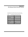
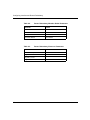
Appendix A
Site Manager Default Parameter Settings
Appendix B
Router Redundancy Examples
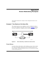
Example 1: Two Routers at the Same Site .................................................................... B-1
Router Bootup ......................................................................................................... B-1
Possible Scenarios .................................................................................................. B-2
Secondary Router Degraded ............................................................................ B-2
Secondary Router Becomes Inoperable ........................................................... B-2
Primary Router Degraded ................................................................................. B-2
Primary Router Fails ......................................................................................... B-2
Possible Complications ........................................................................................... B-3
Router Boots and Cannot Detect Another Member .......................................... B-3
Second Router Boots After First Router’s Bidding Timer Expires .................... B-3
Manual Versus Auto Role Switching ................................................................. B-3
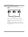
Example 2: Three Routers at the Same Site ................................................................. B-4
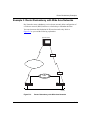
Example 3: Router Redundancy with Wide Area Networks .......................................... B-5
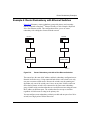
Example 4: Router Redundancy with Ethernet Switches .............................................. B-7
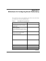
Appendix C
Worksheets for Configuring Router Redundancy
Appendix D
BofL Parameters
Setting BofL Parameters ................................................................................................ D-1
Index
308626-14.00 Rev 00
vii
Figures
Figure 4-1.
Add Circuit Window ..................................................................................4-2
Figure 4-2.
Edit Connector Window ...........................................................................4-3
Figure 4-3.
Circuit Definition Window .........................................................................4-4
Figure 4-4.
Select Primary Window ............................................................................4-5
Figure 4-5.
Circuit Definition Window with Primary Interface .....................................4-6
Figure 5-1.
Main Site Manager Window .....................................................................5-3
Figure 5-2.
Add Circuit Window ..................................................................................5-4
Figure 5-3.
Select Protocols Window .........................................................................5-5
Figure 5-4.
Router Redundancy Circuit Window ........................................................5-6
Figure 5-5.
R.R. Group Global Parameters Configuration Window ............................5-7
Figure 5-6.
RREDUND Router Redundancy Resource List Window .......................5-14
Figure 5-7.
Router Redundancy Resource Window .................................................5-15
Figure 5-8.
Configuration Manager Window in Member Mode .................................5-18
Figure 5-9.
R.R. Member Global Parameters Configuration Window .......................5-19
Figure 5-10. Save Configuration File Window ............................................................5-20
Figure 5-11. Save Configuration File Window ............................................................5-22
Figure B-1.
Router Redundancy: Two Routers at the Same Site .............................. B-1
Figure B-2.
Router Redundancy: Three Routers at the Same Site ........................... B-4
Figure B-3.
Router Redundancy with Wide Area Networks ....................................... B-5
Figure B-4.
Router Redundancy with 281xx Fast Ethernet Switches ........................ B-7
Figure D-1.
Edit CSMA/CD Parameters Window ....................................................... D-2
308626-14.00 Rev 00
ix
Tables
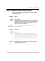
Table 2-1.
Redundancy Protocol PDU Flow Diagram for Role Bidding ....................2-2
Table 2-2.
Redundancy Protocol PDU Flow Diagram for SOS PDUs .......................2-5
Table 3-1.
Using Interface Redundancy across Slots with Router Redundancy .......3-4
Table A-1.
Router Redundancy Group Global Parameters ...................................... A-1
Table A-2.
Router Redundancy Member Global Parameters ................................... A-2
Table A-3.
Router Redundancy Resource Parameters ............................................ A-2
Table C-1.
Group Mode Planning Worksheet ........................................................... C-1
Table C-2.
Resource Planning Worksheet ............................................................... C-2
Table C-3.
Member Mode Planning Worksheet ........................................................ C-2
308626-14.00 Rev 00
xi
Preface
Nortel Networks redundancy services enhance router resilience by enabling a
router to recover from either interface or router failure with minimal delay.
Interface redundancy protects your network from failures of individual LAN
interfaces on a router. Router redundancy protects your network from failures of
the entire router. You can use these services separately or in combination to ensure
smooth and continuous operation of your network.
This guide describes what you do to configure redundancy services on a Nortel
Networks router.
Before You Begin
Before using this guide, you must complete the following procedures. For a new
router:
•
Install the router (see the installation guide that came with your router).
•
Connect the router to the network and create a pilot configuration file (see
Quick-Starting Routers, Configuring BayStack Remote Access, or Connecting
ASN Routers to a Network).
Make sure that you are running the latest version of Nortel Networks BayRS™ and
Site Manager software. For information about upgrading BayRS and Site
Manager, see the upgrading guide for your version of BayRS.
308626-14.00 Rev 00
xiii
Configuring Interface and Router Redundancy
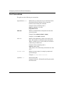
Text Conventions
This guide uses the following text conventions:
angle brackets (< >)
Indicate that you choose the text to enter based on the
description inside the brackets. Do not type the
brackets when entering the command.
Example: If the command syntax is:
ping <ip_address>, you enter:
ping 192.32.10.12
bold text
Indicates command names and options and text that
you need to enter.
Example: Enter show ip {alerts | routes}.
Example: Use the dinfo command.
italic text
Indicates file and directory names, new terms, book
titles, and variables in command syntax descriptions.
Where a variable is two or more words, the words are
connected by an underscore.
Example: If the command syntax is:
show at <valid_route>
valid_route is one variable and you substitute one value
for it.
screen text
Indicates system output, for example, prompts and
system messages.
Example: Set Trap Monitor Filters
separator ( > )
Shows menu paths.
Example: Protocols > IP identifies the IP option on the
Protocols menu.
xiv
308626-14.00 Rev 00
Preface
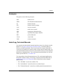
Acronyms
This guide uses the following acronyms:
BofL
Breath of Life
FDDI
Fiber Distributed Data Interface
IP
Internet Protocol
IPX
Internet Packet Exchange
LAN
local area network
MAC
media access control
MIB
management information base
OUI
organizationally unique identifier
PDU
protocol data unit
VLAN
virtual LAN
WAN
wide area network
Hard-Copy Technical Manuals
You can print selected technical manuals and release notes free, directly from the
Internet. Go to support.baynetworks.com/library/tpubs/. Find the product for
which you need documentation. Then locate the specific category and model or
version for your hardware or software product. Using Adobe Acrobat Reader, you
can open the manuals and release notes, search for the sections you need, and print
them on most standard printers. You can download Acrobat Reader free from the
Adobe Systems Web site, www.adobe.com.
You can purchase selected documentation sets, CDs, and technical publications
through the collateral catalog. The catalog is located on the World Wide Web at
support.baynetworks.com/catalog.html and is divided into sections arranged
alphabetically:
•
The “CD ROMs” section lists available CDs.
•
The “Guides/Books” section lists books on technical topics.
•
The “Technical Manuals” section lists available printed documentation sets.
308626-14.00 Rev 00
xv
Configuring Interface and Router Redundancy
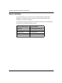
How to Get Help
If you purchased a service contract for your Nortel Networks product from a
distributor or authorized reseller, contact the technical support staff for that
distributor or reseller for assistance.
If you purchased a Nortel Networks service program, contact one of the following
Nortel Networks Technical Solutions Centers:
xvi
Technical Solutions Center
Telephone Number
Billerica, MA
800-2LANWAN (800-252-6926)
Santa Clara, CA
800-2LANWAN (800-252-6926)
Valbonne, France
33-4-92-96-69-68
Sydney, Australia
61-2-9927-8800
Tokyo, Japan
81-3-5402-7041
308626-14.00 Rev 00
Chapter 1
Interface Redundancy Overview
Interface redundancy provides backup of one interface by another within a single
router. It protects your network from partial router or installation failures; it also
enables you to maintain data transmission for critical interfaces without the
expense of two routers.
You configure interfaces to be members of an interface redundancy group. The
group includes an active interface, which performs normal routing and bridging
services, and one or more redundant interfaces, which take over if the active
interface fails.
You can configure multiple interface redundancy groups on the same router.
Active Interface
The active interface performs normal bridging and routing services.
When you configure interface redundancy, you select one interface on the router
to have the highest priority for being the active interface. That interface is the
designated primary interface. Under normal circumstances, the designated
primary interface is the active interface for the redundancy group. If the active
interface fails, however, another interface in the group becomes the new active
interface.
Redundant Interfaces
All members of an interface redundancy group other than the active interface are
redundant interfaces. A redundant interface has no function other than to serve as
a backup.
308626-14.00 Rev 00
1-1
Configuring Interface and Router Redundancy
Interface Roles
Nortel Networks interface redundancy software determines which interface in a
redundancy group becomes the active interface if the current active interface fails.
The software also determines the priority for each of the remaining members of
the group to become the active interface.
Determining the Active Interface
When you boot a router configured with interface redundancy, the designated
primary interface has 12 seconds to become active. If it does become active, data
transmission begins normally.
If the designated primary interface does not become active within 12 seconds, the
redundant interface with the highest priority becomes the active interface, and
transmission begins. The 12-second initialization period occurs only once, and
applies only to the designated primary interface. After initialization, all redundant
interfaces are ready to become active immediately if the active interface fails.
Reset Active Feature
Interface redundancy includes a Reset Active feature that allows you to force the
interface you have designated as primary to become the active interface. Using
this feature may improve network performance. Refer to Chapter 4 for
information about accessing the Reset Active feature.
Determining Priority
The redundant interface with the highest priority becomes the active interface if
the active interface fails.
During startup, if the designated primary interface fails to become active, the
following interfaces become active, in this order:
1. Redundant interfaces on the same slot as the designated primary interface
2. Redundant interfaces on other slots
1-2
308626-14.00 Rev 00
Interface Redundancy Overview
During normal data transfer, if the active interface fails, the following interfaces
become active, in this order:
1. Redundant interfaces on the slot that is processing the routing/bridging table
for this circuit
2. Redundant interfaces on other slots
BofL Parameters and Role Change Speed on Ethernet
When you enable BofL, the router only sends BofL messages if the interface is
idle. If the interface is transmitting regular data traffic, it does not send BofL
messages.
Three parameters control BofL. The BofL Retries parameter sets the number of
BofL messages the interface transmits before the router declares the circuit down.
The number of seconds between BofL messages is the value of the BofL Timeout
parameter divided by the BofL Timeout Divisor parameter.
To increase the speed of detecting failed interfaces and changing roles on Ethernet
connectors, set the BofL Timeout parameter to a short interval, such as 1 second.
If you also set the BofL Retries parameter to 4, and accept the BofL Timeout
Divisor parameter default value of 1, a role change occurs in under 5 seconds. If
you set the BofL Timeout Divisor parameter to a higher value, the router sends
BofL messages so frequently that the cost in LAN bandwidth and CPU overhead
is high.
Refer to Appendix D for parameter descriptions and instructions for using Site
Manager to edit these parameters.
Active Interface MAC Address
When you configure interface redundancy, the active interface uses the following
MAC address in hexadecimal radix:
0x 2y yy A2xx xxxx
•
0x 2 indicates that the address is locally administered by Bay Networks.
•
y yy indicates the circuit number.
•
A2 identifies the Bay Networks organizationally unique identifier (OUI).
•
xx xxxx is the unique router identification number.
308626-14.00 Rev 00
1-3
Configuring Interface and Router Redundancy
The active interface in an interface redundancy group uses the MAC address for
all traffic, including Breath of Life (BofL). The MAC address switches among
interfaces in the interface redundancy group so that it always represents the active
interface.
The MAC address affects the setup of network-layer protocol adjacent hosts on
adjacent routers. For example, if you have adjacent routers and the IP adjacent
host is defined with its next hop being the active interface in an interface
redundancy group, the adjacent host MAC address must be the active interface’s
MAC address; that is, 0x 2y yy A2xx xxxx.
The circuit number maps to a virtual LAN (VLAN) on the router. Multiple
VLANs on the same router can be connected to frame switches.
You find the complete MAC address for the active interface in the interface
management information base (MIB) -- Ethernet or FDDI -- of the router on
which interface redundancy is configured. For example, if you are configuring
Ethernet, you can find the active MAC address in the Ethernet MIB by entering
the following command from the Technician Interface:
get wfCSMACDEntry.wfCSMACDMadr.*
Among the entries displayed in the MIB is the MAC address
0x 2y yy A2xx xxxx, which is used for interface redundancy. If you configure more
than one interface redundancy group on the same router, you will see more than
one entry with the same MAC address. This is not a problem because the two
redundancy groups are in different subnets.
1-4
308626-14.00 Rev 00
Chapter 2
Router Redundancy Overview
Router redundancy protects a network from the irrecoverable failure of an entire
router. You configure routers to be members of a router redundancy group. The
group includes a primary router that performs normal routing and bridging
services, and one or more secondary routers that take over if the primary router
fails.
Note: You can configure multiple router redundancy groups on the same
network.
Primary Router
Nortel Networks router redundancy software allows you to decide which router
has priority to be the primary router. It includes configurable bidding timers and
timeout periods. These values determine how and when a router in a redundancy
group changes roles from secondary to primary.
Dedicated Secondary Router
Nortel Networks recommends that you configure router redundancy so that a
secondary router has no function other than to serve as a backup. A router so
configured is a dedicated secondary router.
You can configure a redundant router to carry other traffic, unrelated to that of its
redundancy group. Be aware, however, that if a secondary router becomes the
primary router in a redundancy group, it stops performing any other data transfer
operations; its role in the group takes precedence over any other functions you
assign it.
308626-14.00 Rev 00
2-1
Configuring Interface and Router Redundancy
Redundancy Protocol
Routers in a redundancy group all begin in the secondary role. A router assumes
the primary role according to the following criteria, which the redundancy
protocol considers in the following order:
1.
Number of good interfaces
2.
Number of reachable resources
3.
Priority to become primary, which you configure (for more information, see
the Priority parameter in Chapter 5)
4.
Lowest member ID (for more information, see the Member ID parameter in
Chapter 5)
For example, if two routers in a router redundancy group have the same number of
good interfaces, the protocol considers the number of reachable resources each
router has. But if one router has a larger number of good interfaces, that router
becomes primary without consideration of subsequent criteria.
The routers use a bidding process to determine which router becomes the primary
router. If the group has more than two members, the bidding process also
determines which of the backup routers is the best secondary router. The bidding
process consists of an exchange of messages called protocol data units (PDUs).
Table 2-1 provides a detailed description of this process.
Table 2-1.
Redundancy Protocol PDU Flow Diagram for Role Bidding
Router A
Starts in secondary role.
Sends Hello PDUs at periodic intervals.
These PDUs start the bidding for the
primary role.
PDU
Router B
Starts in secondary role.
Hello PDU
Receives Hello PDU from Router A and
Role = Secondary stores its contents in the redundancy group
---------------->
database.
Checks to see if Router A is a better primary
router; if so, Router B does not plan to
change roles.
(continued)
2-2
308626-14.00 Rev 00
Router Redundancy Overview
Table 2-1.
Redundancy Protocol PDU Flow Diagram for Role Bidding (continued)
Router A
PDU
Router B
Receives Hello PDU from Router B and
stores its contents in the redundancy
group database.
Hello PDU
Starts sending Hello PDUs at periodic
Role = Secondary intervals; these PDUs are Router B’s bids for
<---------------the primary role.
Checks to see if Router B is a better
primary router; if so, Router A does not
plan to change roles.
After the bidding period times out, the
SOS New
software determines that Router A is the Primary PDU
best primary router.
Role = Secondary
---------------->
Router A sends the SOS New Primary
After the bidding period times out, the
software determines that another member of
the router redundancy group is the best
primary router.
PDU, and then changes role to become
the primary router.
Router B remains in a secondary role and
continues to monitor the redundancy group
status.
Receives the periodic Hello PDU and
Hello PDU
Continues sending periodic Hello PDUs with
updates the redundancy group database, Role = Secondary local interface status information.
including each member’s interface status <---------------information.
Continues sending periodic Primary
Hello PDUs with local interface status
information.
Hello PDU
Role = Primary
---------------->
The Primary Hello PDUs from the
primary router have additional meaning
to other members of the redundancy
group.
Receives the periodic Primary Hello PDUs
and updates the redundancy group
database, including each member’s interface
status information.
Restarts the Primary OK Timer.
Time Passes
SOS New
Router A is in an unknown state; may not Primary PDU
Role = Secondary
have received this PDU.
<---------------Primary router fails.
Primary OK Timer expires for n times.
Router B determines that the primary router
has failed.
Based on information in the redundancy
group database, the software determines
that Router B is the best secondary router to
become the new primary router.
Router B sends an SOS New Primary PDU,
which prevents any other secondary router in
the group from becoming the primary router.
Router B becomes the new primary router.
Router A remains in an unknown state;
may not have received this PDU.
308626-14.00 Rev 00
Hello PDU
Role = Primary
<----------------
As the new primary router, Router B
periodically sends Primary Hello PDUs with
local interface status information.
2-3
Configuring Interface and Router Redundancy
The primary router periodically monitors itself to make sure it is functioning
normally. If it is not functioning properly, a role change occurs, as follows:
1. The primary router notifies the best secondary router that it intends to change
out of the primary role.
2. The best secondary router informs the other members of the impending role
change, and those members start a timer (using the Bidding Timer value) to
prevent additional role changes by other members.
3. The best secondary router assumes primary status.
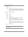
Table 2-2 describes how a primary router changes to a secondary role while the
best secondary router assumes the primary role.
2-4
308626-14.00 Rev 00
Router Redundancy Overview
Table 2-2.
Redundancy Protocol PDU Flow Diagram for SOS PDUs
Router A
PDU
Router B
Router A, currently the primary router,
sends Primary Hello PDUs at periodic
intervals.
Hello PDU
Role = Primary
---------------->
Router B, currently a secondary router,
receives the periodic Primary Hello
PDUs and updates the redundancy
group database.
Router B restarts the Primary OK Timer.
Receives the periodic Hello PDUs and
updates the redundancy group database.
Hello PDU
Role = Secondary
<----------------
Router A detects local partial failures; for SOS PDU
example, an important interface has
Role = Primary
failed. Router A knows that Router B is a ---------------->
better primary router, so Router A plans
to change its role to secondary.
Router B sends periodic Hello PDUs.
Router B, the best secondary router,
receives the SOS PDU, and confirms
that it is the best secondary router by
sending the SOS Reply PDU.
Router A issues an SOS PDU to inform
all members of the redundancy group of
its intention to change out of the primary
role.
Router A, the current primary router,
SOS Reply PDU
receives the SOS Reply PDU with its OK Role = Secondary
indication from Router B.
<----------------
Router B sends the SOS Reply PDU,
indicating that it is ready to be the new
primary router, and that it is OK for the
current primary router to change out of
the primary role.
Router A sends an SOS Primary Goodbye PDU, then changes out of the
primary role.
SOS Primary
Goodbye PDU
Role = Primary
---------------->
Router B receives the SOS Primary
Goodbye PDU.
Router A may not receive this PDU, but
all other members of the redundancy
group do.
SOS New Primary
PDU
Role = Secondary
<----------------
Router B sends the SOS New Primary
PDU to indicate that it is changing roles
to become the new primary router.
Router B changes its role to become the
new primary router.
This message tells the other secondary
members to delay bidding for the new
primary role until after the bidding timer
expires and they detect that there is no
primary router.
Router A may not receive this PDU. All Hello PDU
other members of the redundancy group Role = Primary
do, and update their redundancy group <---------------databases.
308626-14.00 Rev 00
Router B has finished the role change
and is now the new primary router.
Router B sends its first periodic Primary
Hello PDU.
2-5
Configuring Interface and Router Redundancy
Role Change
A router may change out of the primary role because of router failure, failure of
one or more interfaces, or because it cannot reach its resources.
Router Failure
If the primary router in a router redundancy group fails entirely, it obviously is no
longer the best primary router, and a role change occurs, as outlined in Tables 2-1
and 2-2.
Note: If the routers in a router redundancy group are running Version 11.01 or
later, and Version 11.00 or earlier, a router in the group must reboot (also
referred to as a warm boot) to perform a role change. To configure this, see
Chapter 5.
If all the routers in a router redundancy group are running Version 11.01 or
later, a router in the group can perform a role change without rebooting (also
referred to as a hot swap). To configure this, see Chapter 5.
All routers in a router redundancy group must use the same warm boot setting.
Interface Failure
If one or more interfaces on the primary router fail, it is probably no longer the
best primary router, depending on the status of the interfaces on the other routers
in the router redundancy group. If it is not the best primary router, it changes out
of the primary role.
BofL Parameters and Role Change Speed for Ethernet
To increase the speed of detecting failed interfaces and changing roles on Ethernet
connectors, the software automatically shortens the values in the BofL parameters
when you enable router redundancy. The relevant parameters are BofL Timeout,
BofL Retries, and BofL Timeout Divisor.
When you enable BofL, the router only sends BofL messages if the interface is
idle. If the interface is transmitting regular data traffic, it does not send BofL
messages.
2-6
308626-14.00 Rev 00
Router Redundancy Overview
The BofL Retries parameter sets the number of BofL messages the interface
transmits before the router declares the circuit down. The default value for router
redundancy is 4.
The number of seconds between BofL messages is the value of the BofL Timeout
parameter divided by the BofL Timeout Divisor parameter. The default value for
the BofL Timeout parameter is 5 seconds. When you enable router redundancy,
the software sets the default value of the BofL Timeout Divisor parameter to 10,
and thereby shortens the interval between BofL messages to 0.5 seconds.
With a divisor value of 10, and a retries value of 4, the router takes 2 seconds to
detect 4 missed BofLs and initiate a role change. The entire role change procedure
takes about 3 seconds.
You may want to set the retries to a value higher than 4 depending on the nature of
your network. If your network typically carries traffic in bursts, setting the retries
value to 4 could trigger frequent, unnecessary role-switching.
Refer to Appendix D for parameter descriptions and instructions for using Site
Manager to edit these parameters.
Resource Availability
A router is functioning normally if it can reach the resources---servers, printers,
and other devices---with which you configure it to communicate. If a primary
router in a redundancy group cannot reach its resources, it changes out of the
primary role. Resources are determined by IP address, so all resources must be
running TCP/IP.
Nortel Networks redundancy software includes several parameters that allow you
to control how often and how many times a router attempts to ping its resources
(see Chapter 5).
308626-14.00 Rev 00
2-7
Configuring Interface and Router Redundancy
Bypassing the Bidding Process
If your secondary router is performing network functions and you want the
primary router to assume these functions after it switches out of the primary role,
the primary and secondary configuration files for both routers must be identical.
The only parameters that are different between the two routers are the primary
configuration file path (if you are using warm boot) and the member ID.
You must also boot the primary router directly into its primary configuration, and
the secondary router into its secondary configuration, bypassing the bidding
process. Failure to do so can result in connection problems related to both routers
having the same IP address on a LAN.
Requirements
Router redundancy has the following requirements:
2-8
•
Router redundancy is a Nortel Networks proprietary protocol. All routers
running router redundancy must be Nortel Networks routers.
•
Interfaces that you configure for router redundancy must be on networks with
no other routers that require route advertisements on that segment of the
network.
•
All members of a router redundancy group must have exactly the same
configuration for all redundant interfaces except for the member ID, priority,
resources, and primary configuration file path (if you are using warm boot).
•
A router can be a member of only one router redundancy group.
308626-14.00 Rev 00
Chapter 3
Implementation Notes
This chapter provides information about special features of Bay Networks
interface and router redundancy.
Planning Your Network
Configuring router redundancy on your network is somewhat different from
configuring most protocols, because router redundancy involves multiple nodes.
Consider your network requirements and design your interface and router
redundancy groups carefully to maximize the benefits of using redundancy. In
particular, keep in mind the following characteristics of router and interface
redundancy:
•
The interfaces you configure as backed-up interfaces should perform routing
services that you rate as your highest priority.
•
Remember that if a router becomes the primary router in a router redundancy
group, other functions it has been performing while in the secondary role
terminate.
•
Bay Networks recommends that you configure redundant routers as dedicated
redundant routers; that is, with the backup role as their sole function.
•
A router can be a member of only one router redundancy group.
308626-14.00 Rev 00
3-1
Configuring Interface and Router Redundancy
When planning your network for router redundancy, follow these guidelines:
•
Determine the backed-up interfaces in each member of the router redundancy
group.
•
Select the group ID and member IDs for router redundancy, noting the
following:
-- The group ID must be unique for each group in the network.
-- Each member ID must be unique within the group. Role-changing rules
use the member IDs to reassign roles. When two routers have the same
priority, the one with the lowest member ID becomes the primary router
when a role change occurs.
•
Configure more than one interface for router redundancy to avoid a single
point of failure.
Refer to Appendix C for worksheets to help you plan your router redundancy
groups.
Protocols Supported
Interface redundancy works with IP, IPX, spanning tree bridging, source route
bridging, AppleTalk, and VINES.
Router redundancy works with IP, only on stub networks. The network segment
cannot have any other routers that require route advertisements.
LAN Interfaces
Interface and router redundancy support the following LAN interfaces as
redundant interfaces: 10 Mb Ethernet, 100 Mb Ethernet, FDDI, and token ring.
You can configure 10 Mb Ethernet interfaces to back up 100 Mb Ethernet
interfaces. Members of interface redundancy groups other than 10 Mb or 100 Mb
Ethernet (namely, FDDI or token ring) must all be the same type of LAN
interface.
Multiple LAN interfaces, whether the same or different types, can carry the router
redundancy protocol.
3-2
308626-14.00 Rev 00
Implementation Notes
Router Redundancy Requirements
All members of a router redundancy group must
•
Be the same router type; for example, BCN®, BLN®, or ASN™.
•
Have the same hardware configuration. This includes CPU and interface
module types, slot and port locations of the backed-up interfaces, and
resources.
•
Have the same software configuration. For example, all group members must
be running the same router software version and have the same loadable
modules configured.
Using Interface and Router Redundancy in Combination
Use interface redundancy with router redundancy to provide combined protection
from internal router failure and total router failure. The combination of interface
and router redundancy provides better interface protection than is possible using
interface redundancy alone.
You can configure backed-up interfaces within redundant routers, and you can
also configure some interfaces that are not backed up. Interface redundancy allows
data transmission to occur without interruption in the event of a failed interface.
Router redundancy provides the security of uninterrupted network service.
Caution: If you configure interface redundancy across slots with router
redundancy, and the CPU board for the slot with the active interface fails,
router redundancy may take precedence over interface redundancy, even
though there is a member of the interface redundancy group available to
transmit data. The result will be unnecessary delays in data transmission.
308626-14.00 Rev 00
3-3
Configuring Interface and Router Redundancy
Table 3-1 demonstrates what happens when you configure interface redundancy
across slots using router and interface redundancy together.
Table 3-1.
Using Interface Redundancy across Slots with Router Redundancy
Router A
Router B
Router A is in the primary role for router
redundancy. It also has the active interface in the
interface redundancy group.
Router B is in the secondary role.
The CPU board for the active interface fails.
Router A detects that it is no longer the best
primary router, so Router A changes its role to
secondary.
Router B is the new best primary router, and it
assumes the primary role.
Meanwhile, a redundant interface from the
interface redundancy group has become active,
with the result that Router A is again the best
primary router in the router redundancy group.
Router B recognizes that it is no longer the best
primary router and changes out of the primary
role.
Router A assumes the primary role.
Router B is in the secondary role.
Data is moving again.
Note that you can prevent the second role change by configuring the Automatic
Role Switching parameter to Switch on Failure or One Shot Auto (refer to
Chapter 5).
Using the Clear Function
The Clear option from the Router Redundancy pulldown menu allows you to clear
all protocols from all circuits that have router redundancy configured. The Clear
option does not clear any protocols from circuits that are not configured for router
redundancy. This option is useful when you convert a primary router redundancy
configuration to a secondary configuration, because a typical secondary
configuration does not include any of the protocols that the primary has.
To access the Clear option, choose Protocols > Router Redundancy > Clear in the
Configuration Manager main window.
3-4
308626-14.00 Rev 00
Implementation Notes
Compatibility
If you are upgrading from Version 11.0/5.0 or earlier, you must completely
reconfigure router redundancy. If you are upgrading from Version 11.01/5.01 or
later, your existing configuration is compatible with the new software.
308626-14.00 Rev 00
3-5
Chapter 4
Configuring Interface Redundancy
This chapter describes how to configure interface redundancy. It assumes you
have read Configuring and Managing Routers with Site Manager and Chapters 1
and 3 of this guide, and that you have
1. Opened a configuration file in local or remote mode
2. Specified router hardware if this is a local mode configuration file
3. Selected the link- or net-module connector on which you are enabling
interface redundancy
To enable interface redundancy, you must select at least two interfaces as
members of an interface redundancy group. One of the interfaces is the designated
primary interface; under normal circumstances it is the active interface that
provides normal routing/bridging services. The other is the redundant interface; it
takes over if the active interface fails.
Enabling Interface Redundancy
To configure an interface redundancy group:
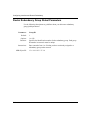
1.
In the Configuration Manager window, select an available LAN interface.
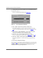
The Add Circuit window opens (Figure 4-1).
308626-14.00 Rev 00
4-1
Configuring Interface and Router Redundancy
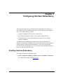
Figure 4-1.
Add Circuit Window
2.
Select all other available LAN interfaces of the same type that you want
to be members of this interface redundancy group.
3.
Click on OK.
Interface redundancy is now enabled on this circuit. The Select Protocols
window opens.
4.
Select the protocols you want to configure on the circuit, and click on OK.
5.
Repeat Steps 1 through 4 to create additional interface redundancy
groups.
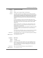
6.
In the Configuration Manager window, select one of the connectors in the
interface redundancy group you just created.
The Edit Connector window opens (Figure 4-2).
4-2
308626-14.00 Rev 00
Configuring Interface Redundancy
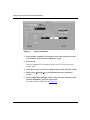
Figure 4-2.
7.
Edit Connector Window
Select Edit Circuit.
The Circuit Definition window opens (Figure 4-3).
308626-14.00 Rev 00
4-3
Configuring Interface and Router Redundancy
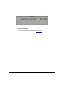
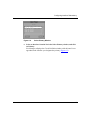
Figure 4-3.
Circuit Definition Window
Note: The Reset Active option in the path Lines > Interface Redundancy >
Primary Interface is available in dynamic mode only. This option allows you to
force the interface you have designated as primary to become the active
interface. Using this option may improve performance.
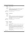
8.
In the Circuit Definition window, choose Lines > Interface Redundancy >
Primary Interface.
The Select Primary window opens (Figure 4-4).
4-4
308626-14.00 Rev 00
Configuring Interface Redundancy
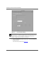
Figure 4-4.
9.
Select Primary Window
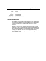
Select an interface from the list in the Select Primary window, and click
on Primary.
Site Manager redisplays the Circuit Definition window with the letter P now
appended to the interface you designated as primary (Figure 4-5).
308626-14.00 Rev 00
4-5
Configuring Interface and Router Redundancy
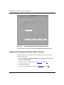
Figure 4-5.
Circuit Definition Window with Primary Interface
10. Choose File > Exit to return to the Configuration Manager window.
Adding and Deleting Interfaces within a Group
To add an interface to an existing interface redundancy group, or to delete an
interface from a group:
1.
In the Configuration Manager window, select any circuit in the group
that you want to change.
The Edit Connector window opens (see Figure 4-2 on page 4-3).
2.
Click on Edit Circuit.
The Circuit Definition window opens (see Figure 4-3 on page 4-4).
4-6
308626-14.00 Rev 00
Configuring Interface Redundancy
3.
To add an interface, select an available line of the same LAN type as the
other members of the group. To delete an interface, select the line you
want to delete from the group.
4.
Choose Lines > Change Lines.
The interface you selected is now added to or deleted from the interface
redundancy group. If only one interface remains on the circuit, the interface
redundancy group no longer exists.
Removing Interface Redundancy from a Circuit
To remove interface redundancy from a circuit:
1.
In the Configuration Manager window, select any member of the
interface redundancy group you want to remove.
The Edit Connector window opens (see Figure 4-2 on page 4-3).
2.
Select Edit Circuit.
The Circuit Definition window opens (see Figure 4-3 on page 4-4).
3.
Deselect all but one member of the interface redundancy group.
4.
Choose Lines > Change Lines.
The interface redundancy group no longer exists.
5.
Choose File > Exit to exit the window.
Note: You can find out whether interface redundancy is configured on a circuit
by selecting that circuit in the Circuit Definition window and checking the
Lines menu. If Interface Redundancy appears dim, it is not configured on the
circuit you selected.
308626-14.00 Rev 00
4-7
Chapter 5
Configuring Router Redundancy
This chapter describes how to configure router redundancy. It assumes you have
read Configuring and Managing Routers with Site Manager and Chapters 2 and 3
of this guide, and that you have already created a local configuration file for a
router without router redundancy.
Note: You cannot configure router redundancy in dynamic or remote mode.
To enable router redundancy, you must choose at least two routers as members of
a router redundancy group. One of the routers will be the primary router; it will
provide normal routing/bridging services. The other router will be the secondary,
backup router; it will take over if the primary router fails.
When you enable router redundancy, you must configure some group and member
parameters. The Configuration Manager supplies default values for the remaining
parameters. Use the directions that follow to enable router redundancy and edit
router redundancy parameters.
For each parameter, this chapter describes default settings, valid parameter
options, the parameter function, instructions for setting the parameter, and the
MIB object ID.
308626-14.00 Rev 00
5-1
Configuring Interface and Router Redundancy
Enabling Router Redundancy
To configure a router redundancy group, you create a group configuration file.
This file is a template that you use to configure each member of the group.
The instructions in this chapter assume that you want to create a router
redundancy group consisting of two members: Router 1 and Router 2. The
configuration file you apply to these routers is named template. This file can be an
existing configuration file to which you are adding router redundancy, or it can be
a new file you create to configure router redundancy and other features.
Creating a Group Configuration File
To create a redundancy group configuration file template, complete the following
steps. All group members will use the values you configure in this file.
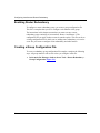
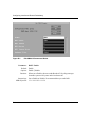
1.
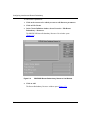
5-2
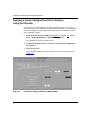
In the main Site Manager window, choose Tools > Router Redundancy >
Group Configuration (Figure 5-1).
308626-14.00 Rev 00
Configuring Router Redundancy
Figure 5-1.
Main Site Manager Window
The standard file selection window opens.
2.
Enter template as the file name.
The standard router window opens.
3.
Choose a router.
The Configuration Manager window opens.
4.
Choose an empty slot.
The Module List window opens.
5.
308626-14.00 Rev 00
Choose a module and click on OK.
5-3
Configuring Interface and Router Redundancy
The Configuration Manager window opens.
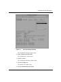
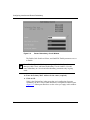
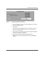
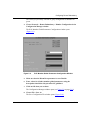
6.
In the Configuration Manager window, select an available connector.
The Add Circuit window opens (Figure 5-2).
Figure 5-2.
7.
Add Circuit Window
Select an available circuit that you want to configure for router
redundancy, and click on OK.
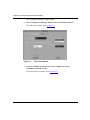
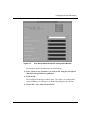
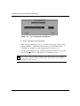
The Select Protocols window opens (Figure 5-3).
5-4
308626-14.00 Rev 00
Configuring Router Redundancy
Figure 5-3.
Select Protocols Window
8.
Scroll through the list and choose Router Redundancy. You can also
choose other protocols that you want to configure.
9.
Click on OK.
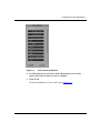
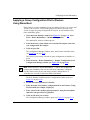
The Router Redundancy Circuit window opens (Figure 5-4).
308626-14.00 Rev 00
5-5
Configuring Interface and Router Redundancy
Figure 5-4.
Router Redundancy Circuit Window
The Enable, Role Switch on Failure, and Send PDU Enable parameters are set
to Enable.
Note: The Configuration Mode opens as “group” in the Configuration
Manager, Add Circuit, and Router Redundancy Circuit windows. You add
router redundancy to a circuit and edit redundancy parameters only in group
mode.
10. Enter the Primary MAC Address for the router (required).
11. Click on OK.
If this is the first interface in the group that you’re configuring for router
redundancy, the R.R. Group Global Parameters Configuration window opens
(Figure 5-5). Subsequent interfaces use the values you supply in this window.
5-6
308626-14.00 Rev 00
Configuring Router Redundancy
Figure 5-5.
R.R. Group Global Parameters Configuration Window
Site Manager supplies default values for all parameters.
12. Enter values for any parameters you want to edit, using the descriptions
that follow this procedure for guidelines.
13. Click on OK.
The Configuration Manager window opens. The circuits you configured for
router redundancy are either green or shaded, depending on your monitor.
14. Choose File > Save, then exit the window.
308626-14.00 Rev 00
5-7
Configuring Interface and Router Redundancy
Router Redundancy Circuit Parameters
Use the following descriptions as guidelines when you edit router redundancy
circuit parameters.
Parameter:
Enable
Default:
Enable
Options:
Enable | Disable
Function:
Instructions:
MIB Object ID:
Parameter:
Choose Disable to stop the redundancy protocol from working on this
router.
1.3.6.1.4.1.18.3.5.17.2.1.2
Role Switch On Failure
Default:
Enable
Options:
Enable | Disable
Function:
Instructions:
MIB Object ID:
5-8
This parameter is automatically set to Enable when you choose Router
Redundancy from the Select Protocols window. If you set this parameter
to Disable, you temporarily disable the redundancy protocol on the router
without deleting your configuration file.
Enables or disables a role change if this interface fails.
Accept the default, Enable, or choose Disable to prevent a role change in
the event this interface fails.
1.3.6.1.4.1.18.3.5.17.2.1.5
308626-14.00 Rev 00
Configuring Router Redundancy
Parameter:
Send PDU Enable
Default:
Enable
Options:
Enable | Disable
Function:
Enables or disables sending of router redundancy PDUs on a per-circuit
basis. This parameter is automatically set to Enable when you choose
Router Redundancy from the Select Protocols window.
At least one interface on each router in the group must have this parameter
enabled so that all routers in the group receive status information about
each other. You may want to disable this parameter on some redundant
interfaces to minimize network traffic on a busy interface.
Instructions:
Choose Enable or Disable.
MIB Object ID:
1.3.6.1.4.1.18.3.5.17.2.1.6
Parameter:
Primary MAC Address
Default:
None
Options:
Any unique, 48-bit MAC address that the network manager provides
Function:
Instructions:
MIB Object ID:
308626-14.00 Rev 00
The primary router uses the MAC address to route data. When the
primary router fails and a backup router becomes the new primary router,
the new primary router assumes this MAC address.
Enter a unique MAC address.
1.3.6.1.4.1.18.3.5.17.2.1.4
5-9
Configuring Interface and Router Redundancy
Router Redundancy Group Global Parameters
Use the following descriptions as guidelines when you edit router redundancy
group global parameters.
Parameter:
Default:
1
Options:
1 to 128
Function:
Instructions:
MIB Object ID:
5-10
Group ID
Specifies the identification number for the redundancy group. Each group
ID number in a network must be unique.
Enter a number from 1 to 128 that you have not already assigned to a
redundancy group on the network.
1.3.6.1.4.1.18.3.5.17.1.4
308626-14.00 Rev 00
Configuring Router Redundancy
Parameter:
Automatic Role Switching
Default:
Auto
Options:
Manual | Auto | Switch on Failure | One Shot Auto
Function:
Auto enables automatic role switching out of the primary role when a
router detects that it is no longer the best primary router, based on priority
settings among the redundant routers. When the primary router switches
out of the primary role, a backup router switches into the primary role.
Anything else that backup router has been doing stops when it becomes
primary.
In some circumstances, you may not want the backup router to stop
processing automatically. If that is the case, set this parameter to Manual.
The warning section of the log will indicate when the routers should
change roles.
Switch on Failure allows a role change only when an interface on the
primary router fails, or a resource becomes unreachable, and does not
consider Priority or Member ID.
One Shot Auto triggers a one-time only automatic role change. Thereafter
a role change occurs only if an interface fails or a resource becomes
unreachable.
If the routers in the redundancy group are using warm boot, the One Shot
Auto function behaves the same as the Switch on Failure function.
Instructions:
MIB Object ID:
Parameter:
Accept the default, Auto, or choose one of the other options according to
the requirements of your network.
1.3.6.1.4.1.18.3.5.17.1.11
Hello Timer
Default:
2 seconds
Options:
1 to 86,400 seconds
Function:
Instructions:
MIB Object ID:
308626-14.00 Rev 00
Specifies the amount of time that the routers in the redundancy group
have for sending each other primary and secondary Hello PDUs. The
routers use Hello PDUs to initiate the bidding process that determines
which router is primary.
Enter a value in the specified range or accept the default of 2.
1.3.6.1.4.1.18.3.5.17.1.15
5-11
Configuring Interface and Router Redundancy
Parameter:
Timeout Threshold
Default:
5
Options:
1 to 100
Function:
Instructions:
MIB Object ID:
Parameter:
Specifies the number of time periods during which the secondary routers
wait to receive a Hello PDU from the primary router before they
determine that the primary has failed.
Enter a number from 1 to 100 or accept the default of 5.
1.3.6.1.4.1.18.3.5.17.1.17
Good Bid Count
Default:
3
Options:
1 to 10
Function:
Instructions:
MIB Object ID:
Parameter:
Specifies the minimum number of good bids to become primary that are
required from the same secondary router before Auto Role Switching
occurs. This parameter has no effect if you have configured manual
role-switching.
Enter a number from 1 to 10 or accept the default of 3.
1.3.6.1.4.1.18.3.5.17.1.12
Bid Duration
Default:
45 seconds
Options:
1 to 65,535 seconds
Function:
Instructions:
Specifies the number of seconds during which routers bid to become the
primary router.
Choose a value in the specified range or accept the default of 45. This
value depends on how fast the routers boot with the configured features.
For example, booting with FDDI interfaces, WAN interfaces with
resources configured (such as servers and printers), OSPF, and so on, may
require a larger value.
Shorten this value if you want to ensure that the first router that boots
becomes the primary.
MIB Object ID:
5-12
1.3.6.1.4.1.18.3.5.17.1.16
308626-14.00 Rev 00
Configuring Router Redundancy
Parameter:
Role Switch Delay Period
Default:
5 seconds
Options:
1 to 86,400 seconds
Function:
Currently not used.
Instructions:
Accept the default.
MIB Object ID:
1.3.6.1.4.1.18.3.5.17.1.19
Configuring Resources
The redundancy protocol uses the Resource parameters to ensure that the primary
router in the router redundancy group can reach the devices with which you have
configured it to communicate. Use the procedure that follows to edit these
parameters.
Although you can edit Resource parameters either in group mode or in member
mode, usually it is best to configure Resource parameters in group mode because
they are identical for all members of a router redundancy group. The exception is
if you use router redundancy with wide area networks (refer to Example 3 in
Appendix B). In this case you configure resources differently among members of
a router redundancy group.
308626-14.00 Rev 00
5-13
Configuring Interface and Router Redundancy
To edit Resource parameters:
1.
Click on the connector for which you want to edit Resource parameters.
2.
Click on Edit Circuit.
3.
In the Circuit Definition window, choose Protocols > Edit Router
Redundancy > Resources.
The RREDUND Router Redundancy Resource List window opens
(Figure 5-6).
Figure 5-6.
4.
RREDUND Router Redundancy Resource List Window
Click on Add.
The Router Redundancy Resource window opens (Figure 5-7).
5-14
308626-14.00 Rev 00
Configuring Router Redundancy
Figure 5-7.
Router Redundancy Resource Window
5.
Enter the IP address of the device you want to configure as a resource for
this router redundancy group.
6.
Click on OK.
The RREDUND Router Redundancy Resource List window opens. The IP
address you entered is highlighted in the list box. Site Manager supplies
default values for all parameters.
7.
Enter values for any parameters you want to edit, using the descriptions
that follow this procedure for guidelines.
8.
Repeat Steps 2 through 5 to configure additional resources.
9.
Click on Done to exit the window and return to the Circuit Definition
window.
308626-14.00 Rev 00
5-15
Configuring Interface and Router Redundancy
Router Redundancy Resource Parameters
Use the following descriptions as guidelines when you edit router redundancy
resource parameters.
Parameter:
Default:
Enable
Options:
Enable | Disable
Function:
Instructions:
MIB Object ID:
Parameter:
This parameter is automatically set to Enable when you choose Router
Redundancy from the Select Protocols window. If you set this parameter
to Disable, you prevent the router from checking on the availability of the
devices with which you configure it to communicate.
Accept the default, Enable.
1.3.6.1.4.1.18.3.5.17.3.1.6
Ping Interval
Default:
600 seconds
Options:
1 to 86,399 seconds
Function:
Instructions:
MIB Object ID:
Parameter:
Specifies the amount of time, in seconds, that the router waits between
attempts to ping the devices with which you configured it to
communicate. The parameter applies when all is functioning normally.
Accept the default, or choose another value in the specified range.
1.3.6.1.4.1.18.3.5.17.3.1.7
Ping Retry Count
Default:
3
Options:
1 to 9
Function:
Instructions:
MIB Object ID:
5-16
Enable Status Update
Specifies the number of times that the primary router tries to ping a device
before it determines that the device is unreachable.
Accept the default, or choose another value in the specified range.
1.3.6.1.4.1.18.3.5.17.3.1.8
308626-14.00 Rev 00
Configuring Router Redundancy
Parameter:
Ping Timeout
Default:
5 seconds
Options:
1 to 10 seconds
Function:
Instructions:
MIB Object ID:
308626-14.00 Rev 00
Specifies the amount of time, in seconds, that the router waits between
attempts to ping the devices with which you configured it to
communicate. This parameter applies when a prior ping has been
unsuccessful.
Accept the default, or choose another value in the specified range.
1.3.6.1.4.1.18.3.5.17.3.1.9
5-17
Configuring Interface and Router Redundancy
Applying a Group Configuration File for Routers
Using Hot Standby
If all routers in a router redundancy group are running Version 11.01 or later, a
router in the group can perform a role switch without rebooting. Use the following
procedure to apply the group configuration file template to each member of this
router redundancy group:
1.
In the main Site Manager window (see Figure 5-1 on page 5-3), choose
Tools > Router Redundancy > Member Configuration.
The standard file selection window opens.
2.
Navigate through the directory structure, and choose the configuration
file, template.
3.
Click on Open File.
The Configuration Manager window opens, but this time in member mode
(Figure 5-8).
Figure 5-8.
5-18
Configuration Manager Window in Member Mode
308626-14.00 Rev 00
Configuring Router Redundancy
The circuit you previously selected for group configuration is shaded or in
green.
4.
Choose Protocols > Router Redundancy > Member Configuration in the
Configuration Manager window.
The R.R. Member Global Parameters Configuration window opens
(Figure 5-9).
Figure 5-9.
R.R. Member Global Parameters Configuration Window
5.
Make sure that the Warm Boot parameter is set to Disable.
6.
Enter values for all other member global parameters, using the
descriptions that follow this procedure for guidelines.
7.
Click on OK when you are done.
The Configuration Manager window opens (see Figure 5-8 on page 5-18).
8.
Choose File > Save As.
The Save Configuration File window opens (Figure 5-10).
308626-14.00 Rev 00
5-19
Configuring Interface and Router Redundancy
Figure 5-10.
9.
Save Configuration File Window
Enter a file name and click on Save.
When naming configuration files, use a filename that complies with the DOS
naming standards -- eight characters followed by a dot followed by three
characters. For example, save the configuration file as Router1.cfg.
Repeat Steps 1 through 8, using a different member ID and Router2.cfg as the
base file name. Do this for each member of a redundancy group.
Note: We recommend that you copy each configuration file to the config file,
in case there is a power failure. (Upon reboot, a router looks for its default
configuration file, config.)
5-20
308626-14.00 Rev 00
Configuring Router Redundancy
Applying a Group Configuration File for Routers
Using Warm Boot
If the routers in a router redundancy group are running Version 11.01 or later, and
Version 11.00 or earlier, a router in the group must reboot to perform a role
switch. To apply the group configuration file template to each member of this
router redundancy group:
1.
In the main Site Manager window (see Figure 5-1 on page 5-3), select
Tools > Router Redundancy > Member Configuration.
The standard file selection window appears.
2.
Select the directory from which you created the file template, and select
your configuration file, template.
3.
Click on Open File.
The Configuration Manager window opens, but this time in member mode
(see Figure 5-8 on page 5-18).
The circuit you previously selected for group configuration is shaded or in
green.
4.
Select Protocols > Router Redundancy > Member Configuration in the
Configuration Manager window (see Figure 5-8 on page 5-18).
Note: Select Protocols > Router Redundancy > Clear to clear all protocols
except router redundancy from circuits with router redundancy configured.
Use this feature when you are converting a primary configuration to a
secondary one. See steps 9 and 10 for further information.
The R.R. Member Global Parameters Configuration window opens (see
Figure 5-9 on page 5-19).
5.
Set the Warm Boot parameter to Enable.
6.
Enter the name of the primary configuration file in the Primary Config
File Path field (for example, 2:alpha.pri).
7.
Enter values for the member global parameters, using the descriptions
that follow this procedure for guidelines.
8.
Click on OK when you are done.
The Configuration Manager window opens (see Figure 5-8 on page 5-18).
308626-14.00 Rev 00
5-21
Configuring Interface and Router Redundancy
9.
Add any protocols you want to include on your nonredundant interfaces.
10. Select File > Save As.
The Save Configuration File window opens (Figure 5-11).
Figure 5-11.
Save Configuration File Window
11. Enter “Alpha” as the file name and click on Primary Save.
Site Manager appends the .pri suffix to the file name and then closes the
window. The Configuration Manager window opens (see Figure 5-8 on page
5-18).
12. Select Protocols > Router Redundancy > Clear to clear all protocols
except router redundancy from the redundant circuits.
13. Select File > Save As in the Configuration Manager window.
The Save Configuration File window opens (see Figure 5-11 on page 5-22).
14. Again enter “Alpha” as the file name. Then click on Secondary Save.
Site Manager appends the .sec suffix to the file name and then closes the
window.
15. Exit from the Configuration Manager.
If router Alpha and router Beta have identical configurations, you can now repeat
steps 1 through 15, using a different member ID and Beta as the base file name. If
the configurations differ, you should modify the nonredundant parts of the
configuration before saving the configuration file.
5-22
308626-14.00 Rev 00
Configuring Router Redundancy
Router Redundancy Member Global Parameters
Use the following descriptions as guidelines when you edit router redundancy
member global parameters.
Parameter:
Enable
Default:
Enable
Options:
Enable | Disable
Function:
Instructions:
MIB Object ID:
Parameter:
This parameter is automatically set to Enable when you choose Router
Redundancy from the Select Protocols window. If you set this parameter
to Disable, you temporarily disable router redundancy on the router
without deleting your configuration file.
Choose Disable to disable router redundancy on this router.
1.3.6.1.4.1.18.3.5.17.1.2
Member ID
Default:
1
Options:
1 to 128
Function:
Instructions:
MIB Object ID:
308626-14.00 Rev 00
Specifies the identification number for this member of the router
redundancy group. Each member ID number in a group must be unique.
For example, if there are two routers in a redundancy group, one router
could have a member ID of 1 and the other could have a member ID
of 2. The role-change rules use the member ID to determine a router’s
priority to become the primary router if the Priority parameter for both
routers is set to the same value.
Enter a number from 1 to 128 that you have not already assigned to a
member of this redundancy group.
1.3.6.1.4.1.18.3.5.17.1.5
5-23
Configuring Interface and Router Redundancy
Parameter:
Priority
Default:
1
Options:
1 to 128
Function:
Instructions:
MIB Object ID:
Parameter:
Indicates this router’s priority to become primary router; the higher the
value, the higher the priority. The router with the highest priority becomes
the primary router. If two routers have the same priority, the router with
the lower member ID number has higher priority to become the primary
router.
Enter a number from 1 to 128.
1.3.6.1.4.1.18.3.5.17.1.14
Warm Boot
Default:
Disable
Options:
Enable | Disable
Function:
Instructions:
Allows router redundancy to operate among routers running BayRS
Version 11.01 or later, and 11.00 or earlier.
If all of the routers in a router redundancy group are running Version
11.01 or later, use the default setting, Disable, to allow a router in the
group to perform a role switch without rebooting. This is also called a hot
standby.
If the routers in a router redundancy group are running Version 11.01 or
later, and Version 11.00 or earlier, a router in the group must reboot, also
called warm boot, to perform a role switch. In this situation, set Warm
Boot to Enable.
MIB Object ID:
1.3.6.1.4.1.18.3.5.17.1.31
Caution: Use the same Warm Boot setting for all routers in a router
redundancy group.
5-24
308626-14.00 Rev 00
Configuring Router Redundancy
Parameter:
Force Role Switch
Default:
Don’t Switch
Options:
Don’t Switch | Switch
Function:
Instructions:
MIB Object ID:
Forces a router to switch out of the primary role when another member of
the redundancy group would make a better primary router, or prevents a
router from doing so. This parameter is valid only for manual role
switching.
Choose Don’t Switch or Switch.
1.3.6.1.4.1.18.3.5.17.1.10
Note: If a slot fails and the software cannot locate the configuration file and
executable image on the volume you specified, the software searches all
volumes to locate these files. We recommend that you store the image on
multiple volumes to be readily available if a slot fails.
Parameter:
Primary Config File Path
Default:
None
Options:
A text string in DOS format, xxxxxxxx.xxx
Function:
Specifies the name of the primary configuration file the router uses when
it boots or reboots as the primary router. This file name is the one you
enter with the Primary Save action described in step 9 of “Applying a
Group Configuration File for Routers Using Warm Boot” on page 5-21.
The example in this guide uses the name Alpha.pri.
Instructions:
To activate this parameter, Warm Boot must be set to Enable. Enter a file
name including the volume ID (vol:filename). For example, enter
2:alpha.pri.
MIB Object ID:
308626-14.00 Rev 00
1.3.6.1.4.1.18.3.5.17.1.20
5-25
Configuring Interface and Router Redundancy
Sending Configuration Files to Routers Using Hot Standby
If you followed the procedure in “Applying a Group Configuration File for
Routers Using Hot Standby” on page 5-18, you have now created configuration
files that allow routers 1 and 2 to use members of a router redundancy group. To
send these files to the appropriate routers, copy them to the router Flash card using
FTP or TFTP. Copy Router1.cfg to router 1, and Router2.cfg to router 2. We
recommend that you copy Router1.cfg to config and Router2.cfg to the config file,
in case there is a power failure. (Upon reboot, a router looks for its default
configuration file, config.)
Sending Configuration Files to Routers Using Warm Boot
If you followed the procedure in “Applying a Group Configuration File for
Routers Using Warm Boot” on page 5-21, you have now created four
configuration files for routers Alpha and Beta to use in their roles as primary and
secondary members of a router redundancy group. To send these files to the
appropriate routers:
1.
Copy the files to a router’s Flash card using FTP or TFTP.
Copy Alpha.pri and Alpha.sec to Alpha, and Beta.pri and Beta.sec to Beta.
2.
Copy Alpha.sec to the config file on the first router. Copy Beta.sec to the
config file on the second router.
Note: We recommend storing the template file on the routers as well.
Configuring Router Redundancy on Model 5380 Routers
You can use router redundancy on a Model 5380 router in several different ways
because of this router’s versatility.
A Model 5380 router may logically be a single-slot router among other single-slot
routers on the same module, or all the slots may logically be ports on the same
router.
5-26
308626-14.00 Rev 00
Configuring Router Redundancy
Configuring Router Redundancy on One 5380 Router
If you are working with a Model 5380 as a single-slot router, you can configure
different slots on the same router module as members of a router redundancy
group. However, the slot number is incorporated in the configuration, so it is
impossible to make identical configuration files for any two slots on the module.
Therefore, you must create two group configuration files, exactly the same except
for the member ID. The following steps describe this procedure:
1.
Create the group mode configuration file for the first slot and save it as
Discovery1.cfg.
2.
Create a second group mode configuration file for the second slot,
identical to the first file, including the same group ID, and save it as
Discovery2.cfg. If you edited any parameters in Discovery1.cfg, make the
same choices for Discovery2.cfg.
3.
Open each of these files in Member Mode, and assign each a unique
member ID. Save each file.
4.
Copy the files to the router’s Flash card.
Configuring Router Redundancy on Different 5380 Routers
You can configure router redundancy so that a slot on one Model 5380 backs up
either the same slot or a different slot on another 5380:
•
To back up the same slot on another 5380, configure router redundancy in the
usual way, following the directions at the beginning of this chapter.
•
To back up a different slot on another 5380, you must create and use two
group configuration files, following the directions in the previous section,
“Configuring Router Redundancy on One 5380 Router.”
Removing Router Redundancy
To remove router redundancy from a circuit or from an entire router:
1.
Create a new configuration file or modify the existing configuration file in
local or remote mode.
2.
Reboot the router.
308626-14.00 Rev 00
5-27
Appendix A
Site Manager Default Parameter Settings
This appendix lists the Site Manager default parameter settings for router
redundancy. Refer to Chapter 5 for instructions on editing these parameters.
Table A-1.
Router Redundancy Group Global Parameters
Parameter
Default
Enable
Enable
Send PDU Enable
Enable
Primary MAC Address
None
Group ID
1
Automatic Role Switching
Auto
Hello Timer
2 seconds
Timeout Threshold
5
Good Bid Count
3
Bid Duration
45 seconds
Role Switch Delay Period
5 seconds
308626-14.00 Rev 00
A-1
Configuring Interface and Router Redundancy
Table A-2.
Parameter
Default
Enable
Enable
Member ID
1
Priority
1
Force Role Switch
Don’t Switch
Table A-3.
A-2
Router Redundancy Member Global Parameters
Router Redundancy Resource Parameters
Parameter
Default
Enable Status Update
Enable
Ping Interval
600 seconds
Ping Retry Count
3
Ping Timeout
5 seconds
308626-14.00 Rev 00
Appendix B
Router Redundancy Examples
This appendix contains three examples of router configurations that use router
redundancy.
Example 1: Two Routers at the Same Site
This example shows how router redundancy works in a configuration with two
routers in the redundancy group, both in the same location. Figure B-1 illustrates
two routers configured as a redundancy group in an Ethernet or FDDI network.
Router A
Router B
FDDI
RRE0001A
Figure B-1.
Router Redundancy: Two Routers at the Same Site
Router Bootup
Upon router bootup, both members of the redundancy group are in the secondary
role. They bid to determine which of the routers will assume the primary role
(refer to Chapter 1). When the bidding time expires, the selected primary member
switches into the primary role.
308626-14.00 Rev 00
B-1
Configuring Interface and Router Redundancy
Possible Scenarios
The sections below describe possible scenarios and how they would affect the
redundant routers.
Secondary Router Degraded
Degradation of the secondary router’s interface and ability to reach resources does
not affect the current operation of the primary router. This change does affect the
primary and best-secondary selection process because the degraded secondary
router has a lesser chance to become primary.
Secondary Router Becomes Inoperable
Degradation of the secondary router to the extent that it is inoperable does not
affect the operation of the primary router. However, if the primary router detects
local faults, it must remain primary and continue data transfer as best it can.
Primary Router Degraded
If the degree of degradation in the primary router is so slight that it is still the best
primary router, no change occurs.
If the degradation is such that the current primary router is no longer the best
primary, role switch to a new primary may occur, depending on the availability of
a secondary router, and on how you have set the Automatic Role Switching
parameter. The primary and best-secondary selection process is the same as during
initial bootup.
Primary Router Fails
The sudden failure of the primary router causes the best secondary router to
switch roles to primary. Because the primary and best-secondary selection process
is performed continuously and involves all members of the router redundancy
group, no bidding process need occur at this time, and the switch occurs with
minimal delay.
B-2
308626-14.00 Rev 00
Router Redundancy Examples
Possible Complications
The following sections describe complications that can occur when you use router
redundancy.
Router Boots and Cannot Detect Another Member
If a member of a router redundancy group boots and cannot detect any other
member of its redundancy group within the bidding period, it switches roles to
become the primary router, because it is the only member from which to select the
primary.
Second Router Boots After First Router’s Bidding Timer Expires
If the first router has booted and a second router boots after the first router’s
bidding period expires, the first router may be in the process of switching roles to
become the primary router. During the switching process, the first router does not
send PDUs, so when the second router boots and begins its own bidding period, it
may not detect the first router until the first router has completed the role switch.
To avoid a situation in which both routers switch roles to become primary, set the
bidding period for a longer time than the time required to perform a role switch.
Manual Versus Auto Role Switching
If the first router has booted and a second router boots after the first router’s
bidding period expires, and if you configured the router to use manual role
switching, the first router continues to act as the primary router even if the second
router would be a better primary. The software alerts you, and it is up to you to
initiate the role switch. If you configure the router to use auto role switching, the
routers perform the role switch automatically. If you configure the router to use
one-shot auto, the routers perform the role switch automatically once; after that a
switch occurs only when an interface fails or when a resource becomes
unreachable. If you configure the router to use switch on failure, a switch occurs
only when an interface fails or when a resource becomes unreachable.
During manual role switching, a secondary router switches its role to primary if it
does not detect a primary router in the group.
308626-14.00 Rev 00
B-3
Configuring Interface and Router Redundancy
Example 2: Three Routers at the Same Site
Figure B-2 illustrates a router redundancy group with three routers at the same
site.
Router A
Router B
Router C
FDDI
RRE0002A
Figure B-2.
Router Redundancy: Three Routers at the Same Site
The only difference between having two members and three members in a router
redundancy group is that the best-secondary selection process becomes
meaningful.
Any degradation of a secondary member may cause a new best secondary to be
selected. Because the best-secondary selection process occurs upon any state
change within the router redundancy group, the designation of the best-secondary
router is current at all times.
B-4
308626-14.00 Rev 00
Router Redundancy Examples
Example 3: Router Redundancy with Wide Area Networks
Bay Networks router redundancy services do not currently allow configuration of
a wide area network (WAN) interface as a backed-up or redundant interface.
You can circumvent this limitation for IP-based networks only. Refer to
Figure B-3 as you read the following explanation.
Remote router
Modem
Modem
FDDI
Router A
Router B
RRE0003B
Figure B-3.
308626-14.00 Rev 00
Router Redundancy with Wide Area Networks
B-5
Configuring Interface and Router Redundancy
To provide redundancy for this WAN:
1.
Define the remote interface on the other side of the WAN as a resource in
the configuration of Router A.
2.
Set the Automatic Role Switching parameter to Auto for Router B.
These two steps allow the primary and best-secondary router selection process
to consider the WAN interface as a resource, and to use the unavailability of
this resource to trigger role switching.
3.
Configure Router B to have a higher priority than Router A to become
the primary router.
Router B will assume the primary role only when Router A, with the lower
priority to be primary, loses the remote router as a resource.
4.
Configure Router B with a dial-on-demand circuit, but disable outbound
calling.
Router B is now capable of receiving a dialed call.
For instructions on configuring dial lines, refer to Configuring Dial Services.
5.
Configure the remote router with dial backup.
The remote router will only initiate a call to Router B if the WAN line to
Router A fails.
If the WAN interface becomes nonfunctional for any reason, the resource defined
for it is unreachable. This causes Router A, the current primary router, to cease
being the best primary router, and a role switch occurs. Router B, with its dial-up
connection to the remote router, becomes the primary router. Note, however, that
because Router A and Router B must have identical configurations, the remote
router must initiate the dial backup connection.
The effect is that the dial-up connection is a redundant interface for the WAN
connection. Note that in this case the dial-up synchronous interface between
Router B and the remote router is active only when the WAN interface fails.
Router A and Router B can be at the branch office; the remote router is at the
central or regional office.
B-6
308626-14.00 Rev 00
Router Redundancy Examples
Example 4: Router Redundancy with Ethernet Switches
Figure B-4 illustrates a router redundancy group with primary and secondary
routers connected to BayStack™ Ethernet switches, in this example a BayStack
281xx Fast Ethernet switch. This configuration allows you to use router
redundancy with a bridged or frame-switched network.
Router A
Router B
Hub A
Hub B
281XX switch
281XX switch
RRE0005A
Figure B-4.
Router Redundancy with 281xx Fast Ethernet Switches
The routers have the same MAC address, and their redundancy configurations are
identical in all other ways. Using connected hubs allows each switch to use only
one port to connect to both routers. Because the switches use the spanning tree
algorithm, only one of the switch ports is in use at any time. Neither switch can
detect that its partner switch is also connected to the same router redundancy
group. Neither switch can detect that there are two different routers using the same
MAC address on different ports. The switches therefore accept or send data
regardless of which router is acting in the primary role.
You can configure router redundancy with only one hub and one port of one 281xx
switch, but a single point of failure then exists.
308626-14.00 Rev 00
B-7
Appendix C
Worksheets for Configuring Router Redundancy
These worksheets assume a router redundancy group of three routers, and can help
you configure your own router redundancy group.
Table C-1.
Group Mode Planning Worksheet
Planning Issue/Parameter
Redundancy Group
Router Type
All in group must be the same; for example,
BCN, BLN, ASN
Hardware Configuration
CPU and interface module type, slot and port
locations of the backed-up interfaces must be the
same
Software Configuration
Software version and loadable modules
configured must be the same
Primary MAC Address for Backed-Up Interfaces
1.
2.
3.
4.
IP Addresses for Backed-Up Interfaces
1.
2.
3.
4.
Group ID
Automatic Role Switching
Hello Timer
Timeout Threshold
(continued)
308626-14.00 Rev 00
C-1
Configuring Interface and Router Redundancy
Table C-1.
Group Mode Planning Worksheet (continued)
Planning Issue/Parameter
Redundancy Group
Good Bid Count
Bid Duration
Table C-2.
Resource Planning Worksheet
Planning Issue/Parameter
Router A
Router B
Router C
Enable Status Update
Ping Interval
Ping Retry Count
Ping Timeout
IP Addresses for Resources
1.
2.
3.
4.
Table C-3.
Member Mode Planning Worksheet
Parameter
Router A
Router B
Router C
Member ID
Priority to Become Primary
Force Role Switch
C-2
308626-14.00 Rev 00
Appendix D
BofL Parameters
Setting BofL Parameters
BofL parameters affect the speed of detecting failed interfaces.
You set BofL parameters from the Edit CSMA/CD Parameters window in Site
Manager. From the Configuration Manager window, the path is Circuits > Edit
Circuits > Circuit List window > Edit > Circuit Definition window > Lines > Edit
Lines window > Edit CSMA/CD Parameters window (Figure D-1). Use the
parameter descriptions that follow as guides when you edit these parameters.
308626-14.00 Rev 00
D-1
Configuring Interface and Router Redundancy
Figure D-1.
Edit CSMA/CD Parameters Window
Parameter:
Default:
Enable
Options:
Enable | Disable
Function:
Instructions:
MIB Object ID:
D-2
BOFL Enable
When set to Enable, the router sends Breath of Life polling messages
from this system to all systems on the local network.
Set to Enable or Disable. We recommend that you enable BofL.
1.3.6.1.4.1.18.3.4.1.1.59
308626-14.00 Rev 00
BofL Parameters
Parameter:
BOFL Timeout
Default:
5 seconds
Options:
1 to 60 seconds
Function:
Specifies the time between transmissions of Breath of Life messages from
this Ethernet interface. Timeout occurs if five periods elapse without a
successful BofL message transmission. When timeout occurs, the router
disables and reenables this Ethernet interface.
This parameter is valid only if you set BofL Enable to Enable.
Instructions:
MIB Object ID:
Parameter:
Accept the default, or specify a new value up to 60 seconds.
1.3.6.1.4.1.18.3.4.1.1.59
BOFL Retries
Default:
5 (4 when the interface is configured for Router Redundancy)
Options:
1 to 5 retries
Function:
Instructions:
MIB Object ID:
308626-14.00 Rev 00
Specifies the number of BofL messages this interface can retransmit
before the router declares the circuit down.
Either accept the default, or specify a lower value. Use this parameter in
conjunction with the BOFL Timeout Divisor and BOFL Timeout
parameters to decrease the time it takes the router to declare an interface
down.
1.3.6.1.4.1.18.3.4.1.1.59
D-3
Configuring Interface and Router Redundancy
Parameter:
BOFL Timeout Divisor
Default:
1 (10 when the interface is configured for Router Redundancy)
Options:
An integer 1 to 59, less than or equal to the value of the BOFL Timeout
parameter
Function:
The BOFL Timeout parameter specifies a time period between
transmissions of Breath of Life messages from this Ethernet interface.
Beginning with Router Software Version 11.01, the actual time between
BofL transmissions is the value of the BOFL Timeout parameter divided
by the value of the BOFL Timeout Divisor parameter. When set to a value
greater than 1, this parameter reduces the value of BOFL Timeout.
When you configure Router Redundancy on an interface, Site Manager
automatically sets this parameter to reduce the time between BofL
transmissions. If the circuit goes down, the interface reaches the BOFL
Retries value sooner, thus reducing the time it takes the router to declare a
circuit down.
Instructions:
Increase the value of this parameter if you want line status to be detected
in less than 1-second intervals.
For example, with the BOFL Timeout parameter set to 5 seconds and the
BOFL Timeout Divisor set to 10, the router sends a BofL message
every 0.5 seconds (5 divided by 10). With BOFL Timeout set to 5 seconds
and the BOFL Timeout Divisor set to 1, transmissions occur every 5
seconds.
MIB Object ID:
D-4
1.3.6.1.4.1.18.3.4.1.1.60
308626-14.00 Rev 00
Index
Numbers
100-Mb Ethernet, 3-2
10-Mb Ethernet, 3-2
A
acronyms, xv
active interface, defined, 1-1
adding interfaces to a group, 4-6
configuring
interface redundancy, 4-1 to 4-7
resources for redundant routers, 5-13 to 5-17
router redundancy, 5-1 to 5-27
requirements, 3-3
conventions, text, xiv
customer support, xvi
D
AppleTalk, 3-2
applying a group configuration file, 5-18, 5-21
dedicated secondary router, defined, 2-1
auto role switching, B-3
deleting interfaces from a group, 4-6
Automatic Role Switching parameter, 5-11, B-2
designated primary interface, defined, 1-1
B
E
Bid Duration parameter, 5-12
Enable parameter (group), 5-6, 5-8
bidding period, B-3
Enable parameter (member), 5-23
bidding process for router redundancy, 2-2 to 2-5
Enable Status Update parameter (resource), 5-16
BOFL parameters
role change speed, 1-3, 2-6
enabling
interface redundancy, 4-1
router redundancy, 5-2
BofL parameters, D-1
C
changing out of the primary role (router redundancy),
2-6
Clear function, 5-21
configuration examples for router redundancy, B-1 to
B-7
configuration files
applying to routers, 5-18, 5-21
creating, 5-2
sending to the routers, 5-26
308626-14.00 Rev 00
examples of router redundancy configurations, B-1 to
B-7
F
FDDI, 3-2
Force Role Switch parameter, 5-25
G
Good Bid Count parameter, 5-12
group configuration files
applying, 5-18, 5-21
Index-1
creating, 5-2
M
group configuration mode, 5-6
group global parameters
Automatic Role Switching, 5-11
Bid Duration, 5-12
Enable, 5-8
Good Bid Count, 5-12
Group ID, 5-10
Hello Timer, 5-11
Primary MAC Address, 5-9
Role Switch Delay Period, 5-13
Send PDU Enable, 5-9
Timeout Threshold, 5-12
manual role switching, B-3
member global parameters
Enable, 5-23
Force Role Switch, 5-25
Member ID, 5-23
Priority, 5-24
Member ID parameter, 5-23
member mode, 5-18, 5-21
N
Group ID parameter, 5-10
network planning for redundancy services, 3-1, C-1
H
O
Hello Timer parameter, 5-11
one-shot auto role switching, B-3
I
P
implementation notes, 3-1
parameter default settings, A-1
interface failure in router redundancy, 2-7
PDU flow diagram, 2-2 to 2-5
interface redundancy
adding or deleting interfaces, 4-6
combined with router redundancy, 3-3
configuring, 4-1 to 4-7
overview, 1-1
priority rules, 1-2
protocols supported, 3-2
removing from a circuit, 4-7
switching rules, 1-2
PDUs, 2-2
IP, 3-2
IPX, 3-2
L
Ping Interval parameter, 5-16
Ping Retry Count parameter, 5-16
Ping Timeout parameter, 5-17
planning your network for redundancy services, 3-1
Primary MAC Address parameter, 5-9
primary router
changing out of primary role, 2-6
defined, 2-1
Priority parameter, 5-24
priority rules for interface redundancy, 1-2
product support, xvi
LAN interfaces
100-Mb Ethernet, 3-2
10-Mb Ethernet, 3-2
FDDI, 3-2
Token Ring, 3-2
Index-2
protocol data units (PDUs)
defined, 2-2
used in role bidding, 2-2 to 2-5
publications
hard copy, xv
308626-14.00 Rev 00
R
T
redundancy protocol, 2-2 to 2-5
technical publications, xv
redundant interface, defined, 1-1
technical support, xvi
removing interface redundancy from a circuit, 4-7
template, group configuration file, creating, 5-2
removing router redundancy from a circuit or a router,
5-27
text conventions, xiv
resource availability, 2-7
Token Ring, 3-2
resource parameters
Enable Status Update, 5-16
Ping Interval, 5-16
Ping Retry Count, 5-16
Ping Timeout, 5-17
resources, configuring, 5-13 to 5-17
Timeout Threshold parameter, 5-12
V
VINES, 3-2
W
Role Switch Delay Period parameter, 5-13
role switching, B-3
router redundancy
and wide area network (WAN) interfaces, B-5
bidding process, 2-2 to 2-5
combined with interface redundancy, 3-3
configuration examples, B-1 to B-7
configuring, 5-1 to 5-27
dedicated secondary router, 2-1
group global parameter descriptions, 5-8 to 5-13
member global parameters descriptions, 5-23 to
5-25
primary router, 2-1
protocols supported, 3-2
removing, 5-27
requirements, 3-3
resource parameter descriptions, 5-16 to 5-17
role changes, 2-6
worksheets, C-1
wide area network (WAN) interfaces and router
redundancy, B-5
worksheets for router redundancy, C-1
S
Send PDU Enable parameter, 5-6, 5-9
sending the configuration files to the routers, 5-26
source route bridging, 3-2
spanning tree bridging, 3-2
support, Nortel Networks, xvi
switch on failure role switching, B-3
switching rules for interface redundancy, 1-2
308626-14.00 Rev 00
Index-3