1
falcon.book Page 1 Monday, July 10, 2000 11:08 AM
Part No. 208700-A
August 2000
4401 Great America Parkway
Santa Clara, CA 95054
Using the Business Policy
Switch 2000
falcon.book Page 2 Monday, July 10, 2000 11:08 AM
2
Copyright © 2000 Nortel Networks
All rights reserved. Printed in the USA. August 2000.
The information in this document is subject to change without notice. The statements, configurations, technical
data, and recommendations in this document are believed to be accurate and reliable, but are presented without
express or implied warranty. Users must take full responsibility for their applications of any products specified in
this document. The information in this document is proprietary to Nortel Networks NA Inc.
Trademarks
NORTEL NETWORKS is a trademark of Nortel Networks.
Bay Networks, ACE, AFN, AN, BCN, BLN, BN, BNX, CN, FRE, LN, Optivity, Optivity Policy Services, and PPX
are registered trademarks and Advanced Remote Node, ANH, ARN, ASN, BayRS, BaySecure, BayStack,
BayStream, BCC, BCNX, BLNX, Centillion, EtherSpeed, FN, IP AutoLearn, Passport, SN, SPEX, Switch Node,
System 5000, and TokenSpeed are trademarks of Nortel Networks.
Microsoft, MS, MS-DOS, Win32, Windows, and Windows NT are registered trademarks of Microsoft Corporation.
All other trademarks and registered trademarks are the property of their respective owners.
Statement of Conditions
In the interest of improving internal design, operational function, and/or reliability, Nortel Networks NA Inc.
reserves the right to make changes to the products described in this document without notice.
Nortel Networks NA Inc. does not assume any liability that may occur due to the use or application of the
product(s) or circuit layout(s) described herein.
USA Requirements Only
Note: This equipment has been tested and found to comply with the limits for a Class A digital device, pursuant to
Part 15 of the FCC rules. These limits are designed to provide reasonable protection against harmful interference
when the equipment is operated in a commercial environment. This equipment generates, uses, and can radiate
radio frequency energy. If it is not installed and used in accordance with the instruction manual, it may cause
harmful interference to radio communications. Operation of this equipment in a residential area is likely to cause
harmful interference, in which case users will be required to take whatever measures may be necessary to correct
the interference at their own expense.
European Requirements Only
EN 55 022 Statement
This is to certify that the Nortel Networks Business Policy Switch 2000 is shielded against the generation of radio
interference in accordance with the application of Council Directive 89/336/EEC, Article 4a. Conformity is
declared by the application of EN 55 022 Class A (CISPR 22).
Warning: This is a Class A product. In a domestic environment, this product may cause radio interference, in
which case, the user may be required to take appropriate measures.
Achtung: Dieses ist ein Gerät der Funkstörgrenzwertklasse A. In Wohnbereichen können bei Betrieb dieses
Gerätes Rundfunkstörungen auftreten, in welchen Fällen der Benutzer für entsprechende Gegenmaßnahmen
verantwortlich ist.
Attention: Ceci est un produit de Classe A. Dans un environnement domestique, ce produit risque de créer des
interférences radioélectriques, il appartiendra alors à l’utilisateur de prendre les mesures spécifiques appropriées.
208700-A
falcon.book Page 3 Monday, July 10, 2000 11:08 AM
3
EC Declaration of Conformity
This product conforms to the provisions of Council Directive 89/336/EEC and 73/23/EEC. The Declaration of
Conformity is available on the Nortel Networks World Wide Web site at http://libra2.corpwest.baynetworks.com/
cgi-bin/ndCGI.exe/DocView/.
Japan/Nippon Requirements Only
Voluntary Control Council for Interference (VCCI) Statement
Taiwan Requirements
Bureau of Standards, Metrology and Inspection (BSMI) Statement
Canada Requirements Only
Canadian Department of Communications Radio Interference Regulations
This digital apparatus (Business Policy Switch 2000) does not exceed the Class A limits for radio-noise emissions
from digital apparatus as set out in the Radio Interference Regulations of the Canadian Department of
Communications.
Règlement sur le brouillage radioélectrique du ministère des Communications
Cet appareil numérique (Business Policy Switch 2000) respecte les limites de bruits radioélectriques visant les
appareils numériques de classe A prescrites dans le Règlement sur le brouillage radioélectrique du ministère des
Communications du Canada.
Using the Business Policy Switch 2000
falcon.book Page 4 Monday, July 10, 2000 11:08 AM
4
Nortel Networks NA Inc. Software License Agreement
NOTICE: Please carefully read this license agreement before copying or using the accompanying software or
installing the hardware unit with pre-enabled software (each of which is referred to as “Software” in this
Agreement). BY COPYING OR USING THE SOFTWARE, YOU ACCEPT ALL OF THE TERMS AND
CONDITIONS OF THIS LICENSE AGREEMENT. THE TERMS EXPRESSED IN THIS AGREEMENT ARE
THE ONLY TERMS UNDER WHICH NORTEL NETWORKS WILL PERMIT YOU TO USE THE
SOFTWARE. If you do not accept these terms and conditions, return the product, unused and in the original
shipping container, within 30 days of purchase to obtain a credit for the full purchase price.
1. License Grant. Nortel Networks NA Inc. (“Nortel Networks”) grants the end user of the Software (“Licensee”)
a personal, nonexclusive, nontransferable license: a) to use the Software either on a single computer or, if
applicable, on a single authorized device identified by host ID, for which it was originally acquired; b) to copy the
Software solely for backup purposes in support of authorized use of the Software; and c) to use and copy the
associated user manual solely in support of authorized use of the Software by Licensee. This license applies to the
Software only and does not extend to Nortel Networks Agent software or other Nortel Networks software products.
Nortel Networks Agent software or other Nortel Networks software products are licensed for use under the terms of
the applicable Nortel Networks NA Inc. Software License Agreement that accompanies such software and upon
payment by the end user of the applicable license fees for such software.
2. Restrictions on use; reservation of rights. The Software and user manuals are protected under copyright laws.
Nortel Networks and/or its licensors retain all title and ownership in both the Software and user manuals, including
any revisions made by Nortel Networks or its licensors. The copyright notice must be reproduced and included with
any copy of any portion of the Software or user manuals. Licensee may not modify, translate, decompile,
disassemble, use for any competitive analysis, reverse engineer, distribute, or create derivative works from the
Software or user manuals or any copy, in whole or in part. Except as expressly provided in this Agreement,
Licensee may not copy or transfer the Software or user manuals, in whole or in part. The Software and user manuals
embody Nortel Networks’ and its licensors’ confidential and proprietary intellectual property. Licensee shall not
sublicense, assign, or otherwise disclose to any third party the Software, or any information about the operation,
design, performance, or implementation of the Software and user manuals that is confidential to Nortel Networks
and its licensors; however, Licensee may grant permission to its consultants, subcontractors, and agents to use the
Software at Licensee’s facility, provided they have agreed to use the Software only in accordance with the terms of
this license.
3. Limited warranty. Nortel Networks warrants each item of Software, as delivered by Nortel Networks and
properly installed and operated on Nortel Networks hardware or other equipment it is originally licensed for, to
function substantially as described in its accompanying user manual during its warranty period, which begins on the
date Software is first shipped to Licensee. If any item of Software fails to so function during its warranty period, as
the sole remedy Nortel Networks will at its discretion provide a suitable fix, patch, or workaround for the problem
that may be included in a future Software release. Nortel Networks further warrants to Licensee that the media on
which the Software is provided will be free from defects in materials and workmanship under normal use for a
period of 90 days from the date Software is first shipped to Licensee. Nortel Networks will replace defective media
at no charge if it is returned to Nortel Networks during the warranty period along with proof of the date of shipment.
This warranty does not apply if the media has been damaged as a result of accident, misuse, or abuse. The Licensee
assumes all responsibility for selection of the Software to achieve Licensee’s intended results and for the
installation, use, and results obtained from the Software. Nortel Networks does not warrant a) that the functions
contained in the software will meet the Licensee’s requirements, b) that the Software will operate in the hardware or
software combinations that the Licensee may select, c) that the operation of the Software will be uninterrupted or
error free, or d) that all defects in the operation of the Software will be corrected. Nortel Networks is not obligated
to remedy any Software defect that cannot be reproduced with the latest Software release. These warranties do not
apply to the Software if it has been (i) altered, except by Nortel Networks or in accordance with its instructions; (ii)
used in conjunction with another vendor’s product, resulting in the defect; or (iii) damaged by improper
environment, abuse, misuse, accident, or negligence. THE FOREGOING WARRANTIES AND LIMITATIONS
ARE EXCLUSIVE REMEDIES AND ARE IN LIEU OF ALL OTHER WARRANTIES EXPRESS OR IMPLIED,
INCLUDING WITHOUT LIMITATION ANY WARRANTY OF MERCHANTABILITY OR FITNESS FOR A
PARTICULAR PURPOSE. Licensee is responsible for the security of its own data and information and for
maintaining adequate procedures apart from the Software to reconstruct lost or altered files, data, or programs.
208700-A
falcon.book Page 5 Monday, July 10, 2000 11:08 AM
5
4. Limitation of liability. IN NO EVENT WILL NORTEL NETWORKS OR ITS LICENSORS BE LIABLE FOR
ANY COST OF SUBSTITUTE PROCUREMENT; SPECIAL, INDIRECT, INCIDENTAL, OR
CONSEQUENTIAL DAMAGES; OR ANY DAMAGES RESULTING FROM INACCURATE OR LOST DATA
OR LOSS OF USE OR PROFITS ARISING OUT OF OR IN CONNECTION WITH THE PERFORMANCE OF
THE SOFTWARE, EVEN IF NORTEL NETWORKS HAS BEEN ADVISED OF THE POSSIBILITY OF SUCH
DAMAGES. IN NO EVENT SHALL THE LIABILITY OF NORTEL NETWORKS RELATING TO THE
SOFTWARE OR THIS AGREEMENT EXCEED THE PRICE PAID TO NORTEL NETWORKS FOR THE
SOFTWARE LICENSE.
5. Government Licensees. This provision applies to all Software and documentation acquired directly or indirectly
by or on behalf of the United States Government. The Software and documentation are commercial products,
licensed on the open market at market prices, and were developed entirely at private expense and without the use of
any U.S. Government funds. The license to the U.S. Government is granted only with restricted rights, and use,
duplication, or disclosure by the U.S. Government is subject to the restrictions set forth in subparagraph (c)(1) of
the Commercial Computer Software––Restricted Rights clause of FAR 52.227-19 and the limitations set out in this
license for civilian agencies, and subparagraph (c)(1)(ii) of the Rights in Technical Data and Computer Software
clause of DFARS 252.227-7013, for agencies of the Department of Defense or their successors, whichever is
applicable.
6. Use of Software in the European Community. This provision applies to all Software acquired for use within
the European Community. If Licensee uses the Software within a country in the European Community, the
Software Directive enacted by the Council of European Communities Directive dated 14 May, 1991, will apply to
the examination of the Software to facilitate interoperability. Licensee agrees to notify Nortel Networks of any such
intended examination of the Software and may procure support and assistance from Nortel Networks.
7. Term and termination. This license is effective until terminated; however, all of the restrictions with respect to
Nortel Networks’ copyright in the Software and user manuals will cease being effective at the date of expiration of
the Nortel Networks copyright; those restrictions relating to use and disclosure of Nortel Networks’ confidential
information shall continue in effect. Licensee may terminate this license at any time. The license will automatically
terminate if Licensee fails to comply with any of the terms and conditions of the license. Upon termination for any
reason, Licensee will immediately destroy or return to Nortel Networks the Software, user manuals, and all copies.
Nortel Networks is not liable to Licensee for damages in any form solely by reason of the termination of this
license.
8. Export and Re-export. Licensee agrees not to export, directly or indirectly, the Software or related technical
data or information without first obtaining any required export licenses or other governmental approvals. Without
limiting the foregoing, Licensee, on behalf of itself and its subsidiaries and affiliates, agrees that it will not, without
first obtaining all export licenses and approvals required by the U.S. Government: (i) export, re-export, transfer, or
divert any such Software or technical data, or any direct product thereof, to any country to which such exports or
re-exports are restricted or embargoed under United States export control laws and regulations, or to any national or
resident of such restricted or embargoed countries; or (ii) provide the Software or related technical data or
information to any military end user or for any military end use, including the design, development, or production
of any chemical, nuclear, or biological weapons.
9. General. If any provision of this Agreement is held to be invalid or unenforceable by a court of competent
jurisdiction, the remainder of the provisions of this Agreement shall remain in full force and effect. This Agreement
will be governed by the laws of the state of California.
Should you have any questions concerning this Agreement, contact Nortel Networks, 4401 Great America
Parkway, P.O. Box 58185, Santa Clara, California 95054-8185.
LICENSEE ACKNOWLEDGES THAT LICENSEE HAS READ THIS AGREEMENT, UNDERSTANDS IT,
AND AGREES TO BE BOUND BY ITS TERMS AND CONDITIONS. LICENSEE FURTHER AGREES THAT
THIS AGREEMENT IS THE ENTIRE AND EXCLUSIVE AGREEMENT BETWEEN NORTEL NETWORKS
AND LICENSEE, WHICH SUPERSEDES ALL PRIOR ORAL AND WRITTEN AGREEMENTS AND
COMMUNICATIONS BETWEEN THE PARTIES PERTAINING TO THE SUBJECT MATTER OF THIS
AGREEMENT. NO DIFFERENT OR ADDITIONAL TERMS WILL BE ENFORCEABLE AGAINST NORTEL
NETWORKS UNLESS NORTEL NETWORKS GIVES ITS EXPRESS WRITTEN CONSENT, INCLUDING AN
EXPRESS WAIVER OF THE TERMS OF THIS AGREEMENT.
Using the Business Policy Switch 2000
falcon.book Page 6 Monday, July 10, 2000 11:08 AM
6
208700-A
falcon.book Page 7 Monday, July 10, 2000 11:08 AM
Contents 7
Contents
Preface . . . . . . . . . . . . . . . . . . . . . . . . . . . . . . . . . . . . . . . . . . . . . . . . . . . . . . 23
Before you begin . . . . . . . . . . . . . . . . . . . . . . . . . . . . . . . . . . . . . . . . . . . . . . . . . . . . . 24
Text conventions . . . . . . . . . . . . . . . . . . . . . . . . . . . . . . . . . . . . . . . . . . . . . . . . . . . . . 24
How to get help . . . . . . . . . . . . . . . . . . . . . . . . . . . . . . . . . . . . . . . . . . . . . . . . . . . . . . 28
Chapter 1
The Business Policy Switch 2000 . . . . . . . . . . . . . . . . . . . . . . . . . . . . . . . . 29
Physical description . . . . . . . . . . . . . . . . . . . . . . . . . . . . . . . . . . . . . . . . . . . . . . . . . . . 29
Front panel . . . . . . . . . . . . . . . . . . . . . . . . . . . . . . . . . . . . . . . . . . . . . . . . . . . . . . 30
Console port . . . . . . . . . . . . . . . . . . . . . . . . . . . . . . . . . . . . . . . . . . . . . . . . . . 30
Uplink/Expansion slot . . . . . . . . . . . . . . . . . . . . . . . . . . . . . . . . . . . . . . . . . . . 31
Port connectors . . . . . . . . . . . . . . . . . . . . . . . . . . . . . . . . . . . . . . . . . . . . . . . . 31
LED display panel . . . . . . . . . . . . . . . . . . . . . . . . . . . . . . . . . . . . . . . . . . . . . . 32
Back panel . . . . . . . . . . . . . . . . . . . . . . . . . . . . . . . . . . . . . . . . . . . . . . . . . . . . . . . 35
Cascade Module slot . . . . . . . . . . . . . . . . . . . . . . . . . . . . . . . . . . . . . . . . . . . . 35
Cooling fans . . . . . . . . . . . . . . . . . . . . . . . . . . . . . . . . . . . . . . . . . . . . . . . . . . 36
AC power receptacle . . . . . . . . . . . . . . . . . . . . . . . . . . . . . . . . . . . . . . . . . . . . 36
Redundant power supply unit (RPSU) and uninterruptible power
supply (UPS) . . . . . . . . . . . . . . . . . . . . . . . . . . . . . . . . . . . . . . . . . . . . . . . . 38
Features . . . . . . . . . . . . . . . . . . . . . . . . . . . . . . . . . . . . . . . . . . . . . . . . . . . . . . . . . . . . 39
Policy-enabled networking . . . . . . . . . . . . . . . . . . . . . . . . . . . . . . . . . . . . . . . . . . . 39
Virtual Local Area Networks (VLANs) . . . . . . . . . . . . . . . . . . . . . . . . . . . . . . . . . . 40
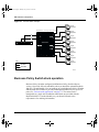
Security . . . . . . . . . . . . . . . . . . . . . . . . . . . . . . . . . . . . . . . . . . . . . . . . . . . . . . . . . 41
RADIUS-based network security . . . . . . . . . . . . . . . . . . . . . . . . . . . . . . . . . . . 43
MAC address-based security . . . . . . . . . . . . . . . . . . . . . . . . . . . . . . . . . . . . . 44
Flash memory storage . . . . . . . . . . . . . . . . . . . . . . . . . . . . . . . . . . . . . . . . . . . . . . 45
Switch software image storage . . . . . . . . . . . . . . . . . . . . . . . . . . . . . . . . . . . . 45
Configuration parameters storage . . . . . . . . . . . . . . . . . . . . . . . . . . . . . . . . . . 45
MultiLink Trunking . . . . . . . . . . . . . . . . . . . . . . . . . . . . . . . . . . . . . . . . . . . . . . . . . 45
Port mirroring (conversation steering) . . . . . . . . . . . . . . . . . . . . . . . . . . . . . . . . . . 46
Autosensing and autonegotiation . . . . . . . . . . . . . . . . . . . . . . . . . . . . . . . . . . . . . 46
RFCs . . . . . . . . . . . . . . . . . . . . . . . . . . . . . . . . . . . . . . . . . . . . . . . . . . . . . . . . 47
Using the Business Policy Switch 2000
falcon.book Page 8 Monday, July 10, 2000 11:08 AM
8 Contents
Standards . . . . . . . . . . . . . . . . . . . . . . . . . . . . . . . . . . . . . . . . . . . . . . . . . . . . 47
SNMP MIB support . . . . . . . . . . . . . . . . . . . . . . . . . . . . . . . . . . . . . . . . . . . . . . . . 47
SNMP trap support . . . . . . . . . . . . . . . . . . . . . . . . . . . . . . . . . . . . . . . . . . . . . . . . 49
BootP automatic IP configuration/MAC address . . . . . . . . . . . . . . . . . . . . . . . . . . 49
Configuration and switch management . . . . . . . . . . . . . . . . . . . . . . . . . . . . . . . . . 50
Multifield packet classification . . . . . . . . . . . . . . . . . . . . . . . . . . . . . . . . . . . . . 51
Chapter 2
Network configuration . . . . . . . . . . . . . . . . . . . . . . . . . . . . . . . . . . . . . . . . . . 53
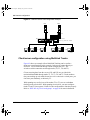
Network configuration examples . . . . . . . . . . . . . . . . . . . . . . . . . . . . . . . . . . . . . . . . . 53
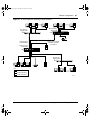
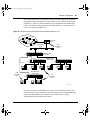
Desktop switch application . . . . . . . . . . . . . . . . . . . . . . . . . . . . . . . . . . . . . . . . . . 53
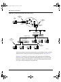
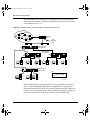
Segment switch application . . . . . . . . . . . . . . . . . . . . . . . . . . . . . . . . . . . . . . . . . . 54
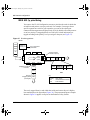
High-density switched workgroup application . . . . . . . . . . . . . . . . . . . . . . . . . . . . 56
Fail-safe stack application . . . . . . . . . . . . . . . . . . . . . . . . . . . . . . . . . . . . . . . . . . . 57
Business Policy Switch stack operation . . . . . . . . . . . . . . . . . . . . . . . . . . . . . . . . . . . . 58
BayStack 400-ST1 Cascade Module . . . . . . . . . . . . . . . . . . . . . . . . . . . . . . . . . . . 59
Cascade A Out connector . . . . . . . . . . . . . . . . . . . . . . . . . . . . . . . . . . . . . . . . 59
Unit Select switch . . . . . . . . . . . . . . . . . . . . . . . . . . . . . . . . . . . . . . . . . . . . . . 60
Cascade A In connector . . . . . . . . . . . . . . . . . . . . . . . . . . . . . . . . . . . . . . . . . 60
Base unit . . . . . . . . . . . . . . . . . . . . . . . . . . . . . . . . . . . . . . . . . . . . . . . . . . . . . . . . 61
Initial installation . . . . . . . . . . . . . . . . . . . . . . . . . . . . . . . . . . . . . . . . . . . . . . . 61
Stack MAC address . . . . . . . . . . . . . . . . . . . . . . . . . . . . . . . . . . . . . . . . . . . . 62
Temporary base unit . . . . . . . . . . . . . . . . . . . . . . . . . . . . . . . . . . . . . . . . . . . . 62
Removing a unit from the stack . . . . . . . . . . . . . . . . . . . . . . . . . . . . . . . . . . . . 63
Stack configurations . . . . . . . . . . . . . . . . . . . . . . . . . . . . . . . . . . . . . . . . . . . . . . . 63
Stack up configurations . . . . . . . . . . . . . . . . . . . . . . . . . . . . . . . . . . . . . . . . . . 63
Stack down configurations . . . . . . . . . . . . . . . . . . . . . . . . . . . . . . . . . . . . . . . 65
Redundant cascade stacking feature . . . . . . . . . . . . . . . . . . . . . . . . . . . . . . . . . . 67
IEEE 802.1Q VLAN workgroups . . . . . . . . . . . . . . . . . . . . . . . . . . . . . . . . . . . . . . . . . 69
IEEE 802.1Q tagging . . . . . . . . . . . . . . . . . . . . . . . . . . . . . . . . . . . . . . . . . . . . . . . 70
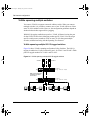
VLANs spanning multiple switches . . . . . . . . . . . . . . . . . . . . . . . . . . . . . . . . . . . . 76
VLANs spanning multiple 802.1Q tagged switches . . . . . . . . . . . . . . . . . . . . 76
VLANS spanning multiple untagged switches . . . . . . . . . . . . . . . . . . . . . . . . . 77
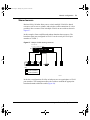
Shared servers . . . . . . . . . . . . . . . . . . . . . . . . . . . . . . . . . . . . . . . . . . . . . . . . . . . 79
VLAN workgroup summary . . . . . . . . . . . . . . . . . . . . . . . . . . . . . . . . . . . . . . . . . . 84
208700-A
falcon.book Page 9 Monday, July 10, 2000 11:08 AM
Contents 9
VLAN configuration rules . . . . . . . . . . . . . . . . . . . . . . . . . . . . . . . . . . . . . . . . . . . . 86
IGMP snooping . . . . . . . . . . . . . . . . . . . . . . . . . . . . . . . . . . . . . . . . . . . . . . . . . . . . . . 86
IGMP snooping configuration rules . . . . . . . . . . . . . . . . . . . . . . . . . . . . . . . . . . . . 91
IEEE 802.1p prioritizing . . . . . . . . . . . . . . . . . . . . . . . . . . . . . . . . . . . . . . . . . . . . . 92
MultiLink Trunks . . . . . . . . . . . . . . . . . . . . . . . . . . . . . . . . . . . . . . . . . . . . . . . . . . . . . . 94
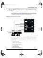
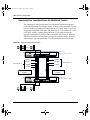
Client/server configuration using MultiLink Trunks . . . . . . . . . . . . . . . . . . . . . . . . 96
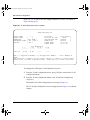
Trunk configuration screen examples . . . . . . . . . . . . . . . . . . . . . . . . . . . . . . . . . . 97
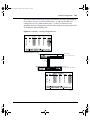
Trunk configuration screen for Switch S1 . . . . . . . . . . . . . . . . . . . . . . . . . . . . 98
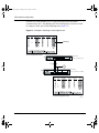
Trunk configuration screen for Switch S2 . . . . . . . . . . . . . . . . . . . . . . . . . . . 100
Trunk Configuration screen for Switch S3 . . . . . . . . . . . . . . . . . . . . . . . . . . . 102
Trunk Configuration screen for Switch S4 . . . . . . . . . . . . . . . . . . . . . . . . . . . 103
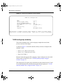
Before you configure trunks . . . . . . . . . . . . . . . . . . . . . . . . . . . . . . . . . . . . . . . . . 105
MultiLink Trunking configuration rules . . . . . . . . . . . . . . . . . . . . . . . . . . . . . . . . . 106
How the MultiLink Trunk reacts to losing distributed trunk members . . . . . . . . . 107
Spanning tree considerations for MultiLink Trunks . . . . . . . . . . . . . . . . . . . . . . . 108
Additional tips about the MultiLink Trunking feature . . . . . . . . . . . . . . . . . . . . . . 111
Port mirroring . . . . . . . . . . . . . . . . . . . . . . . . . . . . . . . . . . . . . . . . . . . . . . . . . . . . . . . 112
Port-based mirroring configuration . . . . . . . . . . . . . . . . . . . . . . . . . . . . . . . . . . . 112
Address-based mirroring configuration . . . . . . . . . . . . . . . . . . . . . . . . . . . . . . . . 115
Port mirroring configuration rules . . . . . . . . . . . . . . . . . . . . . . . . . . . . . . . . . . . . 118
Chapter 3
Using the console interface . . . . . . . . . . . . . . . . . . . . . . . . . . . . . . . . . . . . 119
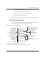
Accessing the CI menus and screens . . . . . . . . . . . . . . . . . . . . . . . . . . . . . . . . . . . . 119
Using the CI menus and screens . . . . . . . . . . . . . . . . . . . . . . . . . . . . . . . . . . . . . . . . 120
Navigating the CI menus and screens . . . . . . . . . . . . . . . . . . . . . . . . . . . . . . . . . 120
Screen fields and descriptions . . . . . . . . . . . . . . . . . . . . . . . . . . . . . . . . . . . . . . . 121
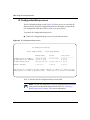
Main Menu . . . . . . . . . . . . . . . . . . . . . . . . . . . . . . . . . . . . . . . . . . . . . . . . . . . . . . . . . 122
IP Configuration/Setup screen . . . . . . . . . . . . . . . . . . . . . . . . . . . . . . . . . . . . . . . 126
Choosing a BootP request mode . . . . . . . . . . . . . . . . . . . . . . . . . . . . . . . . . 128
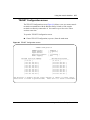
SNMP Configuration screen . . . . . . . . . . . . . . . . . . . . . . . . . . . . . . . . . . . . . . . . 131
System Characteristics screen . . . . . . . . . . . . . . . . . . . . . . . . . . . . . . . . . . . . . . 133
Switch Configuration Menu screen . . . . . . . . . . . . . . . . . . . . . . . . . . . . . . . . . . . 135
MAC Address Table screen . . . . . . . . . . . . . . . . . . . . . . . . . . . . . . . . . . . . . . . . . 138
MAC Address Security Configuration Menu screen . . . . . . . . . . . . . . . . . . . . . . 141
Using the Business Policy Switch 2000
falcon.book Page 10 Monday, July 10, 2000 11:08 AM
10 Contents
MAC Address Security Configuration screen . . . . . . . . . . . . . . . . . . . . . . . . . . . 142
MAC Address Security Port Configuration screen . . . . . . . . . . . . . . . . . . . . . . . . 145
MAC Address Security Port Lists screens . . . . . . . . . . . . . . . . . . . . . . . . . . . . . . 147
Port List Syntax . . . . . . . . . . . . . . . . . . . . . . . . . . . . . . . . . . . . . . . . . . . . . . . 149
Accelerator keys for repetitive tasks . . . . . . . . . . . . . . . . . . . . . . . . . . . . . . . 150
MAC Address Security Table screens . . . . . . . . . . . . . . . . . . . . . . . . . . . . . . . . . 152
VLAN Configuration Menu screen . . . . . . . . . . . . . . . . . . . . . . . . . . . . . . . . . . . . 154
VLAN Configuration screen . . . . . . . . . . . . . . . . . . . . . . . . . . . . . . . . . . . . . . 156
MAC Address Configuration for MAC-SA-Based VLAN screen . . . . . . . . . . 162
VLAN Port Configuration screen . . . . . . . . . . . . . . . . . . . . . . . . . . . . . . . . . . 163
VLAN Display by Port screen . . . . . . . . . . . . . . . . . . . . . . . . . . . . . . . . . . . . 166
Port Configuration screen . . . . . . . . . . . . . . . . . . . . . . . . . . . . . . . . . . . . . . . . . . 167
High Speed Flow Control Configuration screen . . . . . . . . . . . . . . . . . . . . . . . . . 170
Choosing a high speed flow control mode . . . . . . . . . . . . . . . . . . . . . . . . . . . . . . 172
Symmetric mode . . . . . . . . . . . . . . . . . . . . . . . . . . . . . . . . . . . . . . . . . . . . . . 172
Asymmetric mode . . . . . . . . . . . . . . . . . . . . . . . . . . . . . . . . . . . . . . . . . . . . . 173
MultiLink Trunk Configuration Menu screen . . . . . . . . . . . . . . . . . . . . . . . . . . . . 173
MultiLink Trunk Configuration screen . . . . . . . . . . . . . . . . . . . . . . . . . . . . . . 175
MultiLink Trunk Utilization screen . . . . . . . . . . . . . . . . . . . . . . . . . . . . . . . . . 178
Port Mirroring Configuration screen . . . . . . . . . . . . . . . . . . . . . . . . . . . . . . . . . . . 180
Rate Limiting Configuration screen . . . . . . . . . . . . . . . . . . . . . . . . . . . . . . . . . . . 183
IGMP Configuration Menu screen . . . . . . . . . . . . . . . . . . . . . . . . . . . . . . . . . . . . . . . 187
IGMP Configuration screen . . . . . . . . . . . . . . . . . . . . . . . . . . . . . . . . . . . . . . . . . 188
Multicast Group Membership screen . . . . . . . . . . . . . . . . . . . . . . . . . . . . . . . . . . 191
Port Statistics screen . . . . . . . . . . . . . . . . . . . . . . . . . . . . . . . . . . . . . . . . . . . . . . 193
System Log screen . . . . . . . . . . . . . . . . . . . . . . . . . . . . . . . . . . . . . . . . . . . . . . . 197
Stack Operational Mode screen . . . . . . . . . . . . . . . . . . . . . . . . . . . . . . . . . . . . . 199
Console/Comm Port Configuration screen . . . . . . . . . . . . . . . . . . . . . . . . . . . . . 200
Renumber Stack Units screen . . . . . . . . . . . . . . . . . . . . . . . . . . . . . . . . . . . 207
Hardware Unit Information screen . . . . . . . . . . . . . . . . . . . . . . . . . . . . . . . . . . . . 208
Spanning Tree Configuration Menu screen . . . . . . . . . . . . . . . . . . . . . . . . . . . . . 209
Spanning Tree Port Configuration screen . . . . . . . . . . . . . . . . . . . . . . . . . . . . . . 211
Spanning Tree Switch Settings screen . . . . . . . . . . . . . . . . . . . . . . . . . . . . . . . . 214
TELNET Configuration screen . . . . . . . . . . . . . . . . . . . . . . . . . . . . . . . . . . . . . . . 217
Software Download screen . . . . . . . . . . . . . . . . . . . . . . . . . . . . . . . . . . . . . . . . . 219
208700-A
falcon.book Page 11 Monday, July 10, 2000 11:08 AM
Contents 11
LED Indications during the download process . . . . . . . . . . . . . . . . . . . . . . . 223
Configuration File Download/Upload screen . . . . . . . . . . . . . . . . . . . . . . . . . . . . 223
Requirements . . . . . . . . . . . . . . . . . . . . . . . . . . . . . . . . . . . . . . . . . . . . . . . . 226
Chapter 4
Configuring policy-enabled networks . . . . . . . . . . . . . . . . . . . . . . . . . . . . 229
Differentiated Services (DiffServ) overview . . . . . . . . . . . . . . . . . . . . . . . . . . . . . . . . 229
COPS . . . . . . . . . . . . . . . . . . . . . . . . . . . . . . . . . . . . . . . . . . . . . . . . . . . . . . . . . 230
Policy overview . . . . . . . . . . . . . . . . . . . . . . . . . . . . . . . . . . . . . . . . . . . . . . . . . . . . . 230
Configuring policy parameters . . . . . . . . . . . . . . . . . . . . . . . . . . . . . . . . . . . . . . . . . . 232
Chapter 5
Troubleshooting . . . . . . . . . . . . . . . . . . . . . . . . . . . . . . . . . . . . . . . . . . . . . . 233
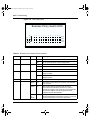
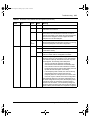
Interpreting the LEDs . . . . . . . . . . . . . . . . . . . . . . . . . . . . . . . . . . . . . . . . . . . . . . . . . 233
Diagnosing and correcting problems . . . . . . . . . . . . . . . . . . . . . . . . . . . . . . . . . . . . . 236
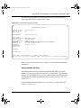
Normal power-up sequence . . . . . . . . . . . . . . . . . . . . . . . . . . . . . . . . . . . . . . . . 237
Port connection problems . . . . . . . . . . . . . . . . . . . . . . . . . . . . . . . . . . . . . . . . . . 238
Autonegotiation modes . . . . . . . . . . . . . . . . . . . . . . . . . . . . . . . . . . . . . . . . . 239
Port interface . . . . . . . . . . . . . . . . . . . . . . . . . . . . . . . . . . . . . . . . . . . . . . . . . 240
Appendix A
Technical specifications . . . . . . . . . . . . . . . . . . . . . . . . . . . . . . . . . . . . . . . 241
Environmental . . . . . . . . . . . . . . . . . . . . . . . . . . . . . . . . . . . . . . . . . . . . . . . . . . . . . . 241
Electrical . . . . . . . . . . . . . . . . . . . . . . . . . . . . . . . . . . . . . . . . . . . . . . . . . . . . . . . . . . . 242
Physical dimensions . . . . . . . . . . . . . . . . . . . . . . . . . . . . . . . . . . . . . . . . . . . . . . . . . . 242
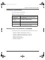
Performance specifications . . . . . . . . . . . . . . . . . . . . . . . . . . . . . . . . . . . . . . . . . . . . 243
Network protocol and standards compatibility . . . . . . . . . . . . . . . . . . . . . . . . . . . . . . 243
Data rate . . . . . . . . . . . . . . . . . . . . . . . . . . . . . . . . . . . . . . . . . . . . . . . . . . . . . . . . . . 244
Interface options . . . . . . . . . . . . . . . . . . . . . . . . . . . . . . . . . . . . . . . . . . . . . . . . . . . . . 244
Safety agency certification . . . . . . . . . . . . . . . . . . . . . . . . . . . . . . . . . . . . . . . . . . . . . 244
Electromagnetic emissions . . . . . . . . . . . . . . . . . . . . . . . . . . . . . . . . . . . . . . . . . . . . 245
Electromagnetic immunity . . . . . . . . . . . . . . . . . . . . . . . . . . . . . . . . . . . . . . . . . . . . . 245
Declaration of Conformity . . . . . . . . . . . . . . . . . . . . . . . . . . . . . . . . . . . . . . . . . . . . . . 245
Using the Business Policy Switch 2000
falcon.book Page 12 Monday, July 10, 2000 11:08 AM
12 Contents
Appendix B
Interoperability in a mixed stack configuration . . . . . . . . . . . . . . . . . . . . 247
Setting up your mixed stack configuration . . . . . . . . . . . . . . . . . . . . . . . . . . . . . . . . . 247
Configuration requirements . . . . . . . . . . . . . . . . . . . . . . . . . . . . . . . . . . . . . . . . . 247
Base unit . . . . . . . . . . . . . . . . . . . . . . . . . . . . . . . . . . . . . . . . . . . . . . . . . . . . 247
Merging the Business Policy Switch into a mixed stack . . . . . . . . . . . . . . . . 248
Automatic failover . . . . . . . . . . . . . . . . . . . . . . . . . . . . . . . . . . . . . . . . . . . . . . . . 249
Temporary base unit . . . . . . . . . . . . . . . . . . . . . . . . . . . . . . . . . . . . . . . . . . . 250
Compatible software versions . . . . . . . . . . . . . . . . . . . . . . . . . . . . . . . . . . . . 250
Using cascade modules . . . . . . . . . . . . . . . . . . . . . . . . . . . . . . . . . . . . . . . . 251
Using the console interface . . . . . . . . . . . . . . . . . . . . . . . . . . . . . . . . . . . . . . 252
Troubleshooting problems . . . . . . . . . . . . . . . . . . . . . . . . . . . . . . . . . . . . . . . . . . 252
Appendix C
Gigabit fiber optical characteristics . . . . . . . . . . . . . . . . . . . . . . . . . . . . . . 253
1000BASE-SX models . . . . . . . . . . . . . . . . . . . . . . . . . . . . . . . . . . . . . . . . . . . . . . . . 253
Operating range . . . . . . . . . . . . . . . . . . . . . . . . . . . . . . . . . . . . . . . . . . . . . . . . . . 253
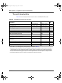
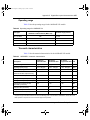
Transmit characteristics . . . . . . . . . . . . . . . . . . . . . . . . . . . . . . . . . . . . . . . . . . . . 254
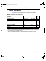
Receive characteristics . . . . . . . . . . . . . . . . . . . . . . . . . . . . . . . . . . . . . . . . . . . . 255
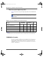
Worst-case power budget and penalties . . . . . . . . . . . . . . . . . . . . . . . . . . . . . . . 256
1000BASE-LX models . . . . . . . . . . . . . . . . . . . . . . . . . . . . . . . . . . . . . . . . . . . . . . . . 256
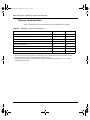
Operating range . . . . . . . . . . . . . . . . . . . . . . . . . . . . . . . . . . . . . . . . . . . . . . . . . . 257
Transmit characteristics . . . . . . . . . . . . . . . . . . . . . . . . . . . . . . . . . . . . . . . . . . . . 257
Receive characteristics . . . . . . . . . . . . . . . . . . . . . . . . . . . . . . . . . . . . . . . . . . . . 258
Worst-case power budget and penalties . . . . . . . . . . . . . . . . . . . . . . . . . . . . . . . 259
Appendix D
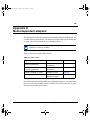
Media dependent adapters . . . . . . . . . . . . . . . . . . . . . . . . . . . . . . . . . . . . . 261
1000BASE-SX: 450-1SR MDA and 450-1SX MDA . . . . . . . . . . . . . . . . . . . . . . . . . . 262
1000BASE-LX: 450-1LR MDA and 450-1LX MDA . . . . . . . . . . . . . . . . . . . . . . . . . . . 264
10BASE-T/100BASE-TX: BPS2000-4TX MDA . . . . . . . . . . . . . . . . . . . . . . . . . . . . . 267
100BASE-FX: BPS2000-2FX MDA and BPS2000-4FX MDA . . . . . . . . . . . . . . . . . . 269
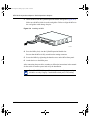
Installing an MDA . . . . . . . . . . . . . . . . . . . . . . . . . . . . . . . . . . . . . . . . . . . . . . . . . . . . 271
Replacing an MDA with a different model . . . . . . . . . . . . . . . . . . . . . . . . . . . . . . . . . 273
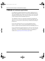
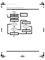
1000BASE-LX multimode applications . . . . . . . . . . . . . . . . . . . . . . . . . . . . . . . . . . . 274
208700-A
falcon.book Page 13 Monday, July 10, 2000 11:08 AM
Contents 13
Appendix E
Quick steps to features . . . . . . . . . . . . . . . . . . . . . . . . . . . . . . . . . . . . . . . . 275
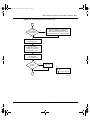
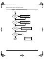
Configuring 802.1Q VLANs . . . . . . . . . . . . . . . . . . . . . . . . . . . . . . . . . . . . . . . . . . . . 275
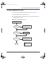
Configuring MultiLink Trunks . . . . . . . . . . . . . . . . . . . . . . . . . . . . . . . . . . . . . . . . . . . 279
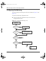
Configuring Port Mirroring . . . . . . . . . . . . . . . . . . . . . . . . . . . . . . . . . . . . . . . . . . . . . 280
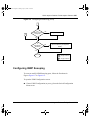
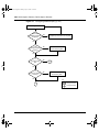
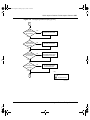
Configuring IGMP Snooping . . . . . . . . . . . . . . . . . . . . . . . . . . . . . . . . . . . . . . . . . . . 281
Appendix F
Connectors and pin assignments . . . . . . . . . . . . . . . . . . . . . . . . . . . . . . . 285
RJ-45 (10BASE-T/100BASE-TX) port connectors . . . . . . . . . . . . . . . . . . . . . . . . . . . 285
MDI and MDI-X devices . . . . . . . . . . . . . . . . . . . . . . . . . . . . . . . . . . . . . . . . . . . . . . . 286
MDI-X to MDI cable connections . . . . . . . . . . . . . . . . . . . . . . . . . . . . . . . . . . . . . 287
MDI-X to MDI-X cable connections . . . . . . . . . . . . . . . . . . . . . . . . . . . . . . . . . . . 287
DB-9 (RS-232-D) Console/Comm Port connector . . . . . . . . . . . . . . . . . . . . . . . . . . . 288
Appendix G
Default Settings . . . . . . . . . . . . . . . . . . . . . . . . . . . . . . . . . . . . . . . . . . . . . . 291
Appendix H
Sample BootP Configuration File . . . . . . . . . . . . . . . . . . . . . . . . . . . . . . . . 299
Index . . . . . . . . . . . . . . . . . . . . . . . . . . . . . . . . . . . . . . . . . . . . . . . . . . . . . . . 301
Using the Business Policy Switch 2000
falcon.book Page 14 Monday, July 10, 2000 11:08 AM
14 Contents
208700-A
falcon.book Page 15 Monday, July 10, 2000 11:08 AM
15
Figures
Figure 1
Business Policy Switch 2000 . . . . . . . . . . . . . . . . . . . . . . . . . . . . . . . . . . 29
Figure 2
Business Policy Switch 2000 front panel . . . . . . . . . . . . . . . . . . . . . . . . . 30
Figure 3
Business Policy Switch 2000 LED display panel . . . . . . . . . . . . . . . . . . . 32
Figure 4
Business Policy Switch 2000 back panel . . . . . . . . . . . . . . . . . . . . . . . . . 35
Figure 5
Removing the cascade module filler panel . . . . . . . . . . . . . . . . . . . . . . . . 36
Figure 6
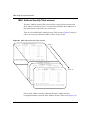
Business Policy Switch 2000 security feature . . . . . . . . . . . . . . . . . . . . . 42
Figure 7
Business Policy Switch used as a desktop switch . . . . . . . . . . . . . . . . . . 54
Figure 8
Business Policy Switch used as a segment switch . . . . . . . . . . . . . . . . . . 55
Figure 9
Configuring power workgroups and a shared media hub . . . . . . . . . . . . . 57
Figure 10
Fail-safe stack example . . . . . . . . . . . . . . . . . . . . . . . . . . . . . . . . . . . . . . 58
Figure 11
BayStack 400-ST1 Cascade Module front-panel components . . . . . . . . . 59
Figure 12
Connecting cascade cables . . . . . . . . . . . . . . . . . . . . . . . . . . . . . . . . . . . 60
Figure 13
Stack up configuration example . . . . . . . . . . . . . . . . . . . . . . . . . . . . . . . . 64
Figure 14
Stack down configuration example . . . . . . . . . . . . . . . . . . . . . . . . . . . . . . 65
Figure 15
Redundant cascade stacking feature . . . . . . . . . . . . . . . . . . . . . . . . . . . . 68
Figure 16
Port-based VLAN example . . . . . . . . . . . . . . . . . . . . . . . . . . . . . . . . . . . . 69
Figure 17
Default VLAN settings . . . . . . . . . . . . . . . . . . . . . . . . . . . . . . . . . . . . . . . 72
Figure 18
Port-based VLAN assignment . . . . . . . . . . . . . . . . . . . . . . . . . . . . . . . . . 73
Figure 19
802.1Q tagging (after port-based VLAN assignment) . . . . . . . . . . . . . . . . 73
Figure 20
Policy-based VLAN assignment . . . . . . . . . . . . . . . . . . . . . . . . . . . . . . . . 74
Figure 21
802.1Q tagging (after policy-based VLAN assignment) . . . . . . . . . . . . . . 74
Figure 22
802.1Q tag assignment . . . . . . . . . . . . . . . . . . . . . . . . . . . . . . . . . . . . . . 75
Figure 23
802.1Q tagging (after 802.1Q tag assignment) . . . . . . . . . . . . . . . . . . . . 75
Figure 24
VLANs spanning multiple 802.1Q tagged switches . . . . . . . . . . . . . . . . . 76
Figure 25
VLANs spanning multiple untagged switches . . . . . . . . . . . . . . . . . . . . . . 77
Figure 26
Possible problems with VLANs and Spanning Tree Protocol . . . . . . . . . . 78
Figure 27
Multiple VLANs sharing resources . . . . . . . . . . . . . . . . . . . . . . . . . . . . . . 79
Figure 28
VLAN broadcast domains within the switch . . . . . . . . . . . . . . . . . . . . . . . 80
Figure 29
Default VLAN Configuration screen example . . . . . . . . . . . . . . . . . . . . . . 81
Using the Business Policy Switch 2000
falcon.book Page 16 Monday, July 10, 2000 11:08 AM
16 Figures
Figure 30
VLAN Configuration screen example . . . . . . . . . . . . . . . . . . . . . . . . . . . . 82
Figure 31
Default VLAN Port Configuration screen example . . . . . . . . . . . . . . . . . . 83
Figure 32
VLAN Port Configuration screen example . . . . . . . . . . . . . . . . . . . . . . . . 84
Figure 33
VLAN configuration spanning multiple switches . . . . . . . . . . . . . . . . . . . . 85
Figure 34
IP Multicast propagation with IGMP routing . . . . . . . . . . . . . . . . . . . . . . . 88
Figure 35
Business Policy Switch filtering IP multicast streams (1 of 2) . . . . . . . . . . 89
Figure 36
Business Policy Switch filtering IP multicast streams (2 of 2) . . . . . . . . . . 90
Figure 37
Prioritizing packets . . . . . . . . . . . . . . . . . . . . . . . . . . . . . . . . . . . . . . . . . . 92
Figure 38
Port transmit queue . . . . . . . . . . . . . . . . . . . . . . . . . . . . . . . . . . . . . . . . . 93
Figure 39
Setting port priority example . . . . . . . . . . . . . . . . . . . . . . . . . . . . . . . . . . . 94
Figure 40
Switch-to-switch trunk configuration example . . . . . . . . . . . . . . . . . . . . . . 95
Figure 41
Switch-to-server trunk configuration example . . . . . . . . . . . . . . . . . . . . . . 96
Figure 42
Client/server configuration example . . . . . . . . . . . . . . . . . . . . . . . . . . . . . 97
Figure 43
Choosing the MultiLink Trunk Configuration Menu screen . . . . . . . . . . . . 98
Figure 44
MultiLink Trunk Configuration screen for Switch S1 . . . . . . . . . . . . . . . . . 99
Figure 45
MultiLink Trunk Configuration screen for Switch S2 . . . . . . . . . . . . . . . . 101
Figure 46
MultiLink Trunk Configuration screen for Switch S3 . . . . . . . . . . . . . . . . 102
Figure 47
MultiLink Trunk Configuration screen for Switch S4 . . . . . . . . . . . . . . . . 104
Figure 48
Loss of distributed trunk members . . . . . . . . . . . . . . . . . . . . . . . . . . . . . 107
Figure 49
Path Cost arbitration example . . . . . . . . . . . . . . . . . . . . . . . . . . . . . . . . 108
Figure 50
Example 1: correctly configured trunk . . . . . . . . . . . . . . . . . . . . . . . . . . 109
Figure 51
Example 2: detecting a misconfigured port . . . . . . . . . . . . . . . . . . . . . . 110
Figure 52
Port-based mirroring configuration example . . . . . . . . . . . . . . . . . . . . . . 113
Figure 53
Port Mirroring Configuration port-based screen example . . . . . . . . . . . . 115
Figure 54
Address-based mirroring configuration example . . . . . . . . . . . . . . . . . . 116
Figure 55
Port Mirroring Configuration address-based screen example . . . . . . . . 117
Figure 56
Map of console interface screens . . . . . . . . . . . . . . . . . . . . . . . . . . . . . . 121
Figure 57
Console interface main menu . . . . . . . . . . . . . . . . . . . . . . . . . . . . . . . . . 123
Figure 58
IP Configuration/Setup screen . . . . . . . . . . . . . . . . . . . . . . . . . . . . . . . . 126
Figure 59
SNMP Configuration screen . . . . . . . . . . . . . . . . . . . . . . . . . . . . . . . . . . 131
Figure 60
System Characteristics screen . . . . . . . . . . . . . . . . . . . . . . . . . . . . . . . . 133
Figure 61
Switch Configuration Menu screen . . . . . . . . . . . . . . . . . . . . . . . . . . . . . 136
Figure 62
MAC Address Table screen . . . . . . . . . . . . . . . . . . . . . . . . . . . . . . . . . . 139
Figure 63
MAC Address Security Configuration Menu screen . . . . . . . . . . . . . . . . 141
Figure 64
MAC Address Security Configuration screen . . . . . . . . . . . . . . . . . . . . . 143
208700-A
falcon.book Page 17 Monday, July 10, 2000 11:08 AM
Figures 17
Figure 65
MAC Security Port Configuration screen (1 of 2) . . . . . . . . . . . . . . . . . . 146
Figure 66
MAC Security Port Configuration screen (2 of 2) . . . . . . . . . . . . . . . . . . 146
Figure 67
MAC Address Security Port Lists screens . . . . . . . . . . . . . . . . . . . . . . . 148
Figure 68
MAC Address Security Port Lists screen . . . . . . . . . . . . . . . . . . . . . . . . 149
Figure 69
MAC Address Security Table screens . . . . . . . . . . . . . . . . . . . . . . . . . . 152
Figure 70
MAC Address Security Table screen . . . . . . . . . . . . . . . . . . . . . . . . . . . 153
Figure 71
VLAN Configuration Menu screen . . . . . . . . . . . . . . . . . . . . . . . . . . . . . 155
Figure 72
VLAN Configuration screen . . . . . . . . . . . . . . . . . . . . . . . . . . . . . . . . . . 157
Figure 73
MAC Address Configuration for MAC-SA Based VLAN screen . . . . . . . 162
Figure 74
VLAN Port Configuration screen . . . . . . . . . . . . . . . . . . . . . . . . . . . . . . 164
Figure 75
VLAN Display by Port screen . . . . . . . . . . . . . . . . . . . . . . . . . . . . . . . . . 166
Figure 76
Port Configuration screen (1 of 2) . . . . . . . . . . . . . . . . . . . . . . . . . . . . . 168
Figure 77
Port Configuration screen (2 of 2) . . . . . . . . . . . . . . . . . . . . . . . . . . . . . 168
Figure 78
High Speed Flow Control Configuration . . . . . . . . . . . . . . . . . . . . . . . . . 171
Figure 79
MultiLink Trunk Configuration Menu screen . . . . . . . . . . . . . . . . . . . . . . 174
Figure 80
MultiLink Trunk Configuration screen . . . . . . . . . . . . . . . . . . . . . . . . . . . 176
Figure 81
MultiLink Trunk Utilization screen (1 of 2) . . . . . . . . . . . . . . . . . . . . . . . . 178
Figure 82
MultiLink Trunk Utilization screen (2 of 2) . . . . . . . . . . . . . . . . . . . . . . . . 179
Figure 83
Port Mirror Configuration screen . . . . . . . . . . . . . . . . . . . . . . . . . . . . . . . 181
Figure 84
Rate Limiting Configuration screen (1 of 2) . . . . . . . . . . . . . . . . . . . . . . 184
Figure 85
Rate Limiting Configuration screen (2 of 2) . . . . . . . . . . . . . . . . . . . . . . 185
Figure 86
IGMP Configuration Menu screen . . . . . . . . . . . . . . . . . . . . . . . . . . . . . 187
Figure 87
IGMP Configuration screen . . . . . . . . . . . . . . . . . . . . . . . . . . . . . . . . . . 189
Figure 88
Multicast Group Membership screen . . . . . . . . . . . . . . . . . . . . . . . . . . . 192
Figure 89
Port Statistics screen . . . . . . . . . . . . . . . . . . . . . . . . . . . . . . . . . . . . . . . 194
Figure 90
System Log screen . . . . . . . . . . . . . . . . . . . . . . . . . . . . . . . . . . . . . . . . . 198
Figure 91
Stack Operational Mode screen . . . . . . . . . . . . . . . . . . . . . . . . . . . . . . . 200
Figure 92
Console/Comm Port Configuration screen . . . . . . . . . . . . . . . . . . . . . . . 201
Figure 93
Renumber Stack Units screen . . . . . . . . . . . . . . . . . . . . . . . . . . . . . . . . 207
Figure 94
Hardware Unit Information screen . . . . . . . . . . . . . . . . . . . . . . . . . . . . . 209
Figure 95
Spanning Tree Configuration Menu screen . . . . . . . . . . . . . . . . . . . . . . 210
Figure 96
Spanning Tree Port Configuration screen (1 of 2) . . . . . . . . . . . . . . . . . 211
Figure 97
Spanning Tree Port Configuration screen (2 of 2) . . . . . . . . . . . . . . . . . 212
Figure 98
Spanning Tree Switch Settings screen . . . . . . . . . . . . . . . . . . . . . . . . . . 214
Figure 99
TELNET Configuration screen . . . . . . . . . . . . . . . . . . . . . . . . . . . . . . . . 217
Using the Business Policy Switch 2000
falcon.book Page 18 Monday, July 10, 2000 11:08 AM
18 Figures
Figure 100 Software Download screen for a Business Policy Switch-only stack . . . 221
Figure 101 Software Download screen for a mixed stack . . . . . . . . . . . . . . . . . . . . . 221
Figure 102 Configuration File Download/Upload screen . . . . . . . . . . . . . . . . . . . . . 224
Figure 103 LED display panel . . . . . . . . . . . . . . . . . . . . . . . . . . . . . . . . . . . . . . . . . . 234
Figure 104 System Uniformity Configuration screen . . . . . . . . . . . . . . . . . . . . . . . . 249
Figure 105 System Characteristics screen . . . . . . . . . . . . . . . . . . . . . . . . . . . . . . . . 251
Figure 106 1000BASE-SX MDA front panels . . . . . . . . . . . . . . . . . . . . . . . . . . . . . . 263
Figure 107 1000BASE-LX MDA front panels . . . . . . . . . . . . . . . . . . . . . . . . . . . . . . 266
Figure 108 BPS2000-4TX MDA front panel . . . . . . . . . . . . . . . . . . . . . . . . . . . . . . . 268
Figure 109 100BASE-FX MDA front panels . . . . . . . . . . . . . . . . . . . . . . . . . . . . . . . 270
Figure 110 Installing an MDA . . . . . . . . . . . . . . . . . . . . . . . . . . . . . . . . . . . . . . . . . . 272
Figure 111 Configuring 802.1Q VLANs (1 of 3 . . . . . . . . . . . . . . . . . . . . . . . . . . . . . 276
Figure 112 Configuring 802.1Q VLANs (2 of 3 . . . . . . . . . . . . . . . . . . . . . . . . . . . . . 277
Figure 113 Configuring 802.1Q VLANs (3 of 3 . . . . . . . . . . . . . . . . . . . . . . . . . . . . . 278
Figure 114 Configuring MultiLink Trunks . . . . . . . . . . . . . . . . . . . . . . . . . . . . . . . . . 279
Figure 115 Configuring Port Mirroring (1 of 2) . . . . . . . . . . . . . . . . . . . . . . . . . . . . . 280
Figure 116 Configuring Port Mirroring (2 of 2) . . . . . . . . . . . . . . . . . . . . . . . . . . . . . 281
Figure 117 Configuring IGMP Snooping (1 of 3) . . . . . . . . . . . . . . . . . . . . . . . . . . . 282
Figure 118 Configuring IGMP Snooping (2 of 3) . . . . . . . . . . . . . . . . . . . . . . . . . . . 283
Figure 119 Configuring IGMP Snooping (3 of 3) . . . . . . . . . . . . . . . . . . . . . . . . . . . 284
Figure 120 RJ-45 (8-Pin Modular) port connector . . . . . . . . . . . . . . . . . . . . . . . . . . 285
Figure 121 MDI-X to MDI cable connections . . . . . . . . . . . . . . . . . . . . . . . . . . . . . . 287
Figure 122 MDI-X to MDI-X cable connections . . . . . . . . . . . . . . . . . . . . . . . . . . . . . 288
Figure 123 DB-9 Console port connector . . . . . . . . . . . . . . . . . . . . . . . . . . . . . . . . . 288
208700-A
falcon.book Page 19 Monday, July 10, 2000 11:08 AM
19
Tables
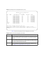
Table 1
Business Policy Switch 2000 front-panel description . . . . . . . . . . . . . . . . 30
Table 2
Business Policy Switch 2000 LED descriptions . . . . . . . . . . . . . . . . . . . . 33
Table 3
Business Policy Switch 2000 back panel descriptions . . . . . . . . . . . . . . . 35
Table 4
International power cord specifications . . . . . . . . . . . . . . . . . . . . . . . . . . 37
Table 5
SNMP MIB support . . . . . . . . . . . . . . . . . . . . . . . . . . . . . . . . . . . . . . . . . 48
Table 6
Support SNMP traps . . . . . . . . . . . . . . . . . . . . . . . . . . . . . . . . . . . . . . . . 49
Table 7
Stack up configuration description . . . . . . . . . . . . . . . . . . . . . . . . . . . . . . 64
Table 8
Stack down configuration description . . . . . . . . . . . . . . . . . . . . . . . . . . . 66
Table 9
Redundant cascade stacking descriptions . . . . . . . . . . . . . . . . . . . . . . . 68
Table 10
Console interface Main Menu options . . . . . . . . . . . . . . . . . . . . . . . . . . 123
Table 11
IP Configuration/Setup screen fields . . . . . . . . . . . . . . . . . . . . . . . . . . . 127
Table 12
SNMP Configuration screen fields . . . . . . . . . . . . . . . . . . . . . . . . . . . . . 132
Table 13
System Characteristics screen fields . . . . . . . . . . . . . . . . . . . . . . . . . . . 134
Table 14
Switch Configuration Menu screen options . . . . . . . . . . . . . . . . . . . . . . 136
Table 15
MAC Address Table screen fields . . . . . . . . . . . . . . . . . . . . . . . . . . . . . 140
Table 16
MAC Address Security Configuration Menu Options . . . . . . . . . . . . . . 142
Table 17
MAC Address Security Configuration fields . . . . . . . . . . . . . . . . . . . . . . 143
Table 18
MAC Security Port Configuration screen fields . . . . . . . . . . . . . . . . . . . 147
Table 19
MAC Address Security Port Lists screen fields . . . . . . . . . . . . . . . . . . . 149
Table 20
MAC Address Security Table Screen Fields . . . . . . . . . . . . . . . . . . . . . 153
Table 21
VLAN Configuration Menu Screen options . . . . . . . . . . . . . . . . . . . . . . . 155
Table 22
VLAN Configuration screen fields . . . . . . . . . . . . . . . . . . . . . . . . . . . . . 157
Table 23
Predefined Protocol Identifier (PID) . . . . . . . . . . . . . . . . . . . . . . . . . . . . 160
Table 24
Reserved PIDs . . . . . . . . . . . . . . . . . . . . . . . . . . . . . . . . . . . . . . . . . . . . 161
Table 25
MAC Address Configuration for MAC-SA Based VLAN screen fields . . 162
Table 26
VLAN Port Configuration screen fields
. . . . . . . . . . . . . . . . . . . . . . . . . 164
Using the Business Policy Switch 2000
falcon.book Page 20 Monday, July 10, 2000 11:08 AM
20 Tables
Table 27
VLAN Display by Port screen fields . . . . . . . . . . . . . . . . . . . . . . . . . . . . 167
Table 28
Port Configuration screen fields
Table 29
High Speed Flow Control Configuration Screen Fields . . . . . . . . . . . . . 171
Table 30
MultiLink Trunk Configuration Menu screen options . . . . . . . . . . . . . . . . 174
Table 31
MultiLink Trunk Configuration screen fields . . . . . . . . . . . . . . . . . . . . . . 177
Table 32
MultiLink Trunk Utilization screen fields . . . . . . . . . . . . . . . . . . . . . . . . . 179
Table 33
Port Mirroring Configuration screen fields . . . . . . . . . . . . . . . . . . . . . . . 181
Table 34
Monitoring modes . . . . . . . . . . . . . . . . . . . . . . . . . . . . . . . . . . . . . . . . . . 183
Table 35
Rate Limiting Configuration screen fields . . . . . . . . . . . . . . . . . . . . . . . . 186
. . . . . . . . . . . . . . . . . . . . . . . . . . . . . . 169
Table 36
IGMP Configuration Menu screen options . . . . . . . . . . . . . . . . . . . . . . . 188
Table 37
IGMP Configuration screen fields . . . . . . . . . . . . . . . . . . . . . . . . . . . . . 189
Table 38
Multicast Group Membership screen options . . . . . . . . . . . . . . . . . . . . . 192
Table 39
Port Statistics screen fields . . . . . . . . . . . . . . . . . . . . . . . . . . . . . . . . . . 195
Table 40
System Log screen fields . . . . . . . . . . . . . . . . . . . . . . . . . . . . . . . . . . . . 199
Table 41
Stack Operational Mode screen fields . . . . . . . . . . . . . . . . . . . . . . . . . . 200
Table 42
Console/Comm Port Configuration screen fields . . . . . . . . . . . . . . . . . . 201
Table 43
Renumber Stack Units screen options
. . . . . . . . . . . . . . . . . . . . . . . . . 208
Table 44
Spanning Tree Configuration Menu screen options
Table 45
Spanning Tree Port Configuration screen fields . . . . . . . . . . . . . . . . . . 212
. . . . . . . . . . . . . . . 210
Table 46
Spanning Tree Switch Settings parameters
Table 47
TELNET Configuration screen fields . . . . . . . . . . . . . . . . . . . . . . . . . . . 218
. . . . . . . . . . . . . . . . . . . . . 215
Table 48
Software Download screen fields
Table 49
Configuration File Download/Upload screen fields . . . . . . . . . . . . . . . . 225
. . . . . . . . . . . . . . . . . . . . . . . . . . . . . 222
Table 50
Parameters not saved to the configuration file . . . . . . . . . . . . . . . . . . . . 227
Table 51
Business Policy Switch LED descriptions . . . . . . . . . . . . . . . . . . . . . . . 234
Table 52
Corrective actions . . . . . . . . . . . . . . . . . . . . . . . . . . . . . . . . . . . . . . . . . 238
Table 53
Environmental specifications . . . . . . . . . . . . . . . . . . . . . . . . . . . . . . . . . 241
Table 54
Electrical parameters
Table 55
Physical dimensions . . . . . . . . . . . . . . . . . . . . . . . . . . . . . . . . . . . . . . . 242
. . . . . . . . . . . . . . . . . . . . . . . . . . . . . . . . . . . . . . 242
Table 56
Performance specifications . . . . . . . . . . . . . . . . . . . . . . . . . . . . . . . . . . 243
Table 57
Interface options . . . . . . . . . . . . . . . . . . . . . . . . . . . . . . . . . . . . . . . . . . 244
Table 58
Operating range for 1000BASE-SX . . . . . . . . . . . . . . . . . . . . . . . . . . . . 253
Table 59
1000BASE-SX transmit characteristics . . . . . . . . . . . . . . . . . . . . . . . . . 254
Table 60
1000BASE-SX receive characteristics . . . . . . . . . . . . . . . . . . . . . . . . . . 255
Table 61
Worst-case 1000BASE-SX power budget and penalties . . . . . . . . . . . . 256
208700-A
falcon.book Page 21 Monday, July 10, 2000 11:08 AM
Tables 21
Table 62
Operating range for 1000BASE-LX . . . . . . . . . . . . . . . . . . . . . . . . . . . . 257
Table 63
1000BASE-LX transmit characteristics . . . . . . . . . . . . . . . . . . . . . . . . . 257
Table 64
1000BASE-LX receive characteristics . . . . . . . . . . . . . . . . . . . . . . . . . . 258
Table 65
Worst-case 1000BASE-LX power budget and penalties . . . . . . . . . . . . 259
Table 66
MDA models
Table 67
1000BASE-SX MDA components . . . . . . . . . . . . . . . . . . . . . . . . . . . . . 264
Table 68
1000BASE-LX MDA components . . . . . . . . . . . . . . . . . . . . . . . . . . . . . 267
Table 69
100BASE-FX MDA components . . . . . . . . . . . . . . . . . . . . . . . . . . . . . . 271
Table 70
RJ-45 port connector pin assignments
Table 71
DB-9 Console port connector pin assignments . . . . . . . . . . . . . . . . . . . 289
Table 72
Factory default settings . . . . . . . . . . . . . . . . . . . . . . . . . . . . . . . . . . . . . 291
. . . . . . . . . . . . . . . . . . . . . . . . . . . . . . . . . . . . . . . . . . . . . 261
. . . . . . . . . . . . . . . . . . . . . . . . . 286
Using the Business Policy Switch 2000
falcon.book Page 22 Monday, July 10, 2000 11:08 AM
22 Tables
208700-A
falcon.book Page 23 Monday, July 10, 2000 11:08 AM
23
Preface
This guide describes the Nortel Networks Business Policy Switch 2000™ features
and uses. The terms “Business Policy Switch 2000” and “Business Policy Switch”
are used synonymously in this document. The Business Policy Switch introduces
policy-enabled networking features to optimize consistent performance and
behavior for your network traffic. The Differentiated Services (DiffServ) network
architecture offers varied levels of service for different types of data traffic.
DiffServ lets you designate a specific level of performance on a per-packet basis.
For more information about configuring policy-enabled networking, see
Chapter 4, “Configuring policy-enabled networks.”
The Business Policy Switch includes a dedicated Uplink Module slot for attaching
optional media dependent adapters (MDAs) that support a range of media types,
including Gigabit Ethernet. Installation instructions are included with each MDA
(see your Nortel Networks sales representative for ordering information). For
more information about the MDAs, see Appendix D, “Media dependent
adapters.”
You can use the Business Policy Switch in:
•
•
A standalone switch configuration.
A Business Policy Switch 2000-only stack configuration.
•
A mixed stack configuration consisting of BayStack 450, BayStack 410, and
Business Policy Switch 2000 switches.
The Business Policy Switch 2000 provides fail-safe stackability when you install
the optional BayStack 400-ST1 Cascade Module.
Using the Business Policy Switch 2000
falcon.book Page 24 Monday, July 10, 2000 11:08 AM
24 Preface
Before you begin
This guide is intended for network managers and administrators with the
following background:
•
•
•
•
Basic knowledge of networks, Ethernet bridging, and IP and IPX routing
Familiarity with networking concepts and terminology
Specific knowledge about the networking devices, protocols, topologies, and
interfaces that comprise your network
Experience with windowing systems, graphical user interfaces (GUIs), or
Web browsers
Text conventions
This guide uses the following text conventions:
angle brackets (< >)
Indicate that you choose the text to enter based on the
description inside the brackets. Do not type the
brackets when entering the command.
Example: If the command syntax is:
ping <ip_address>, you enter:
ping 192.32.10.12
208700-A
bold text
Indicates command names and options and text that
you need to enter.
Example: Enter show ip {alerts | routes}.
Example: Use the dinfo command.
braces ({})
Indicate required elements in syntax descriptions
where there is more than one option. You must choose
only one of the options. Do not type the braces when
entering the command.
Example: If the command syntax is:
show ip {alerts | routes}, you must enter
either:
show ip alerts or show ip routes, but not
both.
falcon.book Page 25 Monday, July 10, 2000 11:08 AM
Preface 25
brackets ([ ])
Indicate optional elements in syntax descriptions. Do
not type the brackets when entering the command.
Example: If the command syntax is:
show ip interfaces [-alerts], you can enter
either:
show ip interfaces or show ip interfaces
-alerts.
ellipsis points (. . . )
Indicate that you repeat the last element of the
command as needed.
Example: If the command syntax is:
ethernet/2/1 [<parameter> <value>] . . . ,
you enter
ethernet/2/1 and as many parameter-value pairs as
needed.
italic text
Indicates file and directory names, new terms, book
titles, and variables in command syntax descriptions.
Where a variable is two or more words, the words are
connected by an underscore.
Example: If the command syntax is:
show at <valid_route>
valid_route is one variable and you substitute one value
for it.
screen text
Indicates system output, for example, prompts and
system messages.
Example: Set Trap Monitor Filters
separator ( > )
Shows menu paths.
Example: Protocols > IP identifies the IP option on the
Protocols menu.
vertical line ( | )
Separates choices for command keywords and
arguments. Enter only one of the choices. Do not type
the vertical line when entering the command.
Example: If the command syntax is:
show ip {alerts | routes}, you enter either:
show ip alerts or show ip routes, but not
both.
Using the Business Policy Switch 2000
falcon.book Page 26 Monday, July 10, 2000 11:08 AM
26 Preface
Related publications
For more information about using the Business Policy Switch 2000, refer to the
following publications:
•
Using Web-based Management for the Business Policy Switch 2000 (part
number 209570-A)
Describes how to use the Web-based management tool to configure switch
features.
•
Installing the Business Policy Switch 2000 (part number 209319-A)
Describes how to install the Business Policy Switch 2000.
•
Release Notes for the Business Policy Switch 2000 (part number 209320-A)
Documents important changes about the software and hardware that are not
covered in other related publications.
•
Installing Media Dependent Adapters (MDA)s (part number 302403-D)
Describes how to install optional MDAs in your Business Policy Switch 2000.
•
Installing the BayStack 400-ST1 Cascade Module (part number 304433-B)
Describes how to connect up to eight switches into a stack configuration by
installing optional BayStack 400-ST1 Cascade Modules.
•
Getting Started with Business Policy Switch 2000 Management Software
Operations (part number 209321-A)
Describes how to install the Java-based device level software management
application.
•
Reference for the Business Policy Switch 2000 Management Software
Operations (part number 209322-A)
Describes how to use the Java-based device level software management
application.
208700-A
falcon.book Page 27 Monday, July 10, 2000 11:08 AM
Preface 27
•
BayStack 10 Power Supply Unit (part number 208558-A)
Describes installation, power-up, power-down and fan replacement
procedures.
•
Release Notes for the BayStack RPSU/UPS (part number 208560-A)
Documents important changes about the RPSU/UPS that are not covered in
other related publications.
•
Installation and Reference for the BayStack RPSU/UPS (part number
208296-A)
Describes how to install the optional RPSU/UPS to your Business Policy
Switch 2000.
•
100 Watt DC-DC Converter Installation and Reference Guide (part number
209132-A)
Describes installation and removal procedures.
•
Reference Note: Gigabit Ethernet Physical Layer Considerations (part
number 201540-B)
Provides information about gigabit transmission over fiber optic cable and
mode conditioning.
You can print selected technical manuals and release notes free, directly from the
Internet. Go to the support.baynetworks.com/library/tpubs/ URL. Find the
product for which you need documentation. Then locate the specific category and
model or version for your hardware or software product. Use Adobe Acrobat
Reader to open the manuals and release notes, search for the sections you need,
and print them on most standard printers. Go to Adobe Systems at
www.adobe.com to download a free copy of Acrobat Reader.
You can purchase selected documentation sets, CDs, and technical publications
though the Internet at the www1.fatbrain.com/documentation/nortel/ URL.
Using the Business Policy Switch 2000
falcon.book Page 28 Monday, July 10, 2000 11:08 AM
28 Preface
How to get help
If you purchased a service contract for your Nortel Networks™ product from a
distributor or authorized reseller, contact the technical support staff for that
distributor or reseller for assistance.
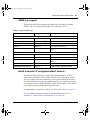
If you purchased a Nortel Networks service program, contact one of the following
Nortel Networks Technical Solutions Centers:
Technical Solutions Center
Telephone
EMEA
(33) (4) 92-966-968
North America
(800) 2LANWAN or (800) 252-6926
Asia Pacific
(61) (2) 9927-8800
China
(800) 810-5000
An Express Routing Code (ERC) is available for many Nortel Networks products
and services. When you use an ERC, your call is routed to a technical support
person who specializes in supporting that product or service. To locate an ERC for
your product or service, go to the www12.nortelnetworks.com/ URL and click
ERC at the bottom of the page.
208700-A
falcon.book Page 29 Monday, July 10, 2000 11:08 AM
The Business Policy Switch 2000
29
Chapter 1
The Business Policy Switch 2000
This chapter introduces the Business Policy Switch 2000 and covers the following
topics:
•
•
Physical description (this page)
Overview of main features (page 39)
Physical description
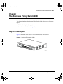
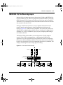
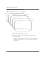
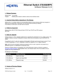
Figure 1 depicts the front and side views of the Business Policy Switch.
Figure 1 Business Policy Switch 2000
9713FA
Using the Business Policy Switch 2000
falcon.book Page 30 Monday, July 10, 2000 11:08 AM
30 The Business Policy Switch 2000
Front panel
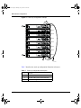
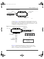
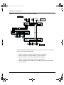
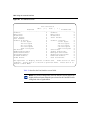
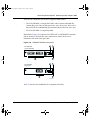
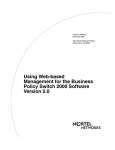
Figure 2 shows the front-panel configuration for the Business Policy Switch 2000.
Descriptions of the front-panel components follow the figure.
For descriptions of the back-panel Business Policy Switch components, see “Back
panel” on page 35.
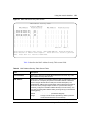
Figure 2 Business Policy Switch 2000 front panel
1
2
3
4
Console Port
Business Policy Switch 2000
1
Uplink/Expansion Module
3
5
7
9
11
13
15
17
19
21
23
25 26 27 28
Cas
Pwr
RPSU Base
2
4
6
8
10
12
14
16
18
20
22
1
3
5
7
9
11
13
15
17
19
21
23
2
4
6
8
10
12
14
16
18
20
22
24
Up
Status Dwn
10/100
Activity
10/100
Activity
24
Business Policy Switch 2000
9712EA
Table 1 Business Policy Switch 2000 front-panel description
1
Console port
2
Uplink/expansion slot
3
Port connectors
4
LED display panel
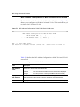
Console port
The console port allows you to access the console interface (CI) screens and
customize your network using the supplied menus and screens (see Chapter 3,
“Using the console interface,” on page 119).
208700-A
falcon.book Page 31 Monday, July 10, 2000 11:08 AM
The Business Policy Switch 2000
31
The console port is a DB-9, RS-232-D male serial port connector. You can use this
connector to connect a management station or console/terminal to the Business
Policy Switch by using a straight-through DB-9 to DB-9 standard serial port
cable. You must use a VT100/ANSI-compatible terminal (for cursor control and
to enable cursor and functions keys) to use the console port. See Installing the
Business Policy Switch 2000 for more information.
Note: The console port is configured as a data communications
equipment (DCE) connector. Ensure that your RS-232 cable pinouts are
configured for DCE connections (see Appendix F, “Connectors and pin
assignments,” on page 285).
The console port default settings are: 9600 baud with eight data bits, one stop bit,
and no parity as the communications format, with flow control set to enabled.
Uplink/Expansion slot
The Uplink/Expansion slot allows you to attach optional media dependent
adapters (MDAs) that support a range of media types (see Appendix D, “Media
dependent adapters,” on page 261 for more information about MDA types
available from Nortel Networks).
Port connectors
The Business Policy Switch uses 10BASE-T/100BASE-TX RJ-45 (8-pin
modular) port connectors.
The 10BASE-T/100BASE-TX port connectors are configured as MDI-X
(media-dependent interface-crossover). These ports connect over straight cables
to the network interface card (NIC) in a node or server, similar to a conventional
Ethernet repeater hub. If you are connecting to an Ethernet hub or Ethernet switch,
use a crossover cable unless an MDI connection exists on the associated port of
the attached device (see “Appendix F, “Connectors and pin assignments,” on page
285).
Using the Business Policy Switch 2000
falcon.book Page 32 Monday, July 10, 2000 11:08 AM
32 The Business Policy Switch 2000
The Business Policy Switch uses autosensing ports designed to operate at 10 Mb/s
(megabits per second) or at 100 Mb/s, depending on the connecting device. These
ports support the IEEE 802.3u autonegotiation standard, which means that when a
port is connected to another device that also supports the IEEE 802.3u standard,
the two devices negotiate the best speed and duplex mode.
The 10BASE-T/100BASE-TX switch ports also support half- and full-duplex
mode operation (refer to Installing the Business Policy Switch 2000).
The 10BASE-T/100BASE-TX RJ-45 ports can connect to 10 Mb/s or 100 Mb/s
Ethernet segments or nodes.
Note: Use only Category 5 copper unshielded twisted pair (UTP) cable
connections when connecting 10BASE-T/100BASE-TX ports.
See Appendix F, “Connectors and pin assignments,” on page 285 for more
information about the RJ-45 port connectors.
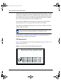
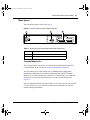
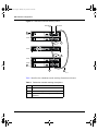
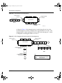
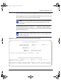
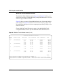
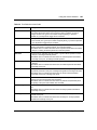
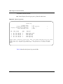
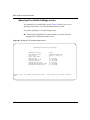
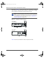
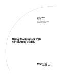
LED display panel
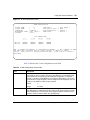
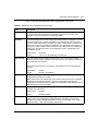
Figure 3 shows the Business Policy Switch LED display panel. See Table 2 for a
description of the LEDs.
Figure 3 Business Policy Switch 2000 LED display panel
Business Policy Switch 2000
Cas
Pwr
1
3
5
7
9
11
13
15
17
19
21
23
Up
Status Dwn
RPSU Base
10/100
Activity
2
4
6
8
10
12
14
16
18
20
22
24
10/100
Activity
9714EA
208700-A
falcon.book Page 33 Monday, July 10, 2000 11:08 AM
The Business Policy Switch 2000
33
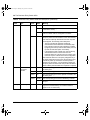
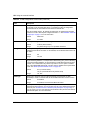
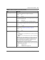
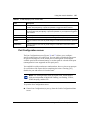
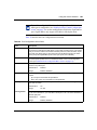
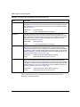
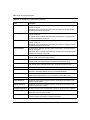
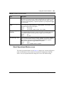
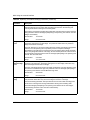
Table 2 Business Policy Switch 2000 LED descriptions
Label
Type
Color
State
Meaning
Pwr
Power status
Green
On
DC power is available to the switch’s internal circuitry.
Off
No AC power to switch or power supply failed.
On
Self-test passed successfully and switch is operational.
Blinking
A nonfatal error occurred during the self-test.
Off
The switch failed the self-test.
On
The switch is connected to the RPSU and can receive
power if needed.
Off
The switch is not connected to the RPSU or RPSU is not
supplying power.
Off
The switch is in standalone mode.
Green
On
The switch is connected to the upstream unit’s Cascade
A In connector.
Amber
On
This unit has detected a problem with the switch
connected to the cascade up connector. In order to
maintain the integrity of the stack, this unit has bypassed
its upstream neighbor and has wrapped the stack
backplane onto an alternate path.
Amber
or
Green
Blinking
Incompatible software revision or unable to obtain a unit
ID (Renumber Stack Unit table full). The unit is on the ring
but cannot participate in the stack configuration.
Off
The switch is in standalone mode.
Green
On
The switch is connected to the downstream unit’s
Cascade A Out connector.
Amber
On
This unit has detected a problem with the switch
connected to the cascade down connector. In order to
maintain the integrity of the stack, this unit has bypassed
its downstream neighbor and has wrapped the stack
backplane onto an alternate path.
Amber
or
Green
Blinking
Incompatible software revision or unable to obtain a unit
ID (Renumber Stack Unit table full). The unit is on the ring
but cannot participate in the stack configuration.
Status
RPSU
Cas Up
System status
RPSU status
Green
Green
Stack mode
Cas Dwn Stack mode
Using the Business Policy Switch 2000
falcon.book Page 34 Monday, July 10, 2000 11:08 AM
34 The Business Policy Switch 2000
Table 2 Business Policy Switch 2000 LED descriptions (continued)
Label
Type
Color
State
Meaning
Base
Base mode
Green
On
The switch is configured as the stack base unit.
Off
The switch is not configured as the stack base unit (or is
in standalone mode).
Blinking
Stack configuration error: indicates that multiple base
units or no base units are configured in the stack.
Amber
On
This unit is operating as the stack configuration’s
temporary base unit. This condition occurs automatically
if the base unit (directly downstream from this unit) fails.
If this happens, the following events take place:
• The two units directly upstream and directly
downstream from the failed unit automatically wrap
their cascade connectors and indicate this condition
by lighting their Cas Up and Cas Dwn LEDs (see Cas
Up and Cas Dwn description in this table).
• If the temporary base unit fails, the next unit directly
downstream from this unit becomes the new
temporary base unit. This process can continue until
there are only two units left in the stack configuration.
This automatic failover is a temporary safeguard only. If
the stack configuration loses power, the temporary base
unit will not power up as the base unit when power is
restored. For this reason, you should always assign the
temporary base unit as the base unit (set the Unit Select
switch to Base) until the failed unit is repaired or replaced.
Green
On
The corresponding port is set to operate at 100 Mb/s, and
the link is good.
Green
Blinking
The corresponding port has been disabled by software.
Amber
On
The corresponding port is set to operate at 10 Mb/s, and
the link is good.
Amber
Blinking
The corresponding port has been disabled by software.
Off
The link connection is bad, or there is no connection to
this port.
Blinking
Indicates network activity for the corresponding port. A
high level of network activity can cause the LEDs to
appear to be on continuously.
10/100
Activity
208700-A
10/100 Mb/s
port speed
indicator
Port activity
Green
falcon.book Page 35 Monday, July 10, 2000 11:08 AM
The Business Policy Switch 2000
35
Back panel
The switch back panel is shown in Figure 4.
Figure 4 Business Policy Switch 2000 back panel
2
1
3
9719EA
Table 3 Business Policy Switch 2000 back-panel descriptions
1
AC power receptacle
2
RPSU connector
3
Cascade Module slot
Cascade Module slot
The Cascade Module slot allows you to attach an optional BayStack 400-ST1
Cascade Module to the switch (see “Stack configurations” on page 63.
You can connect up to eight switches into a redundant stack configuration.
Installation instructions are provided with each BayStack 400-ST1 Cascade
Module (see Installing the BayStack 400-ST1 Cascade Module). Use a flathead
screwdriver to remove the filler panel that covers the Cascade Module slot
(Figure 5).
For more information about cascade modules, see Installing the Cascade 400-ST1
Cascade Module. See your Nortel Networks sales representative for cascade
module ordering information.
Using the Business Policy Switch 2000
falcon.book Page 36 Monday, July 10, 2000 11:08 AM
36 The Business Policy Switch 2000
Figure 5 Removing the cascade module filler panel
9744FA
Cooling fans
Three cooling fans are located on one side of the Business Policy Switch to
provide cooling for the internal components. (See Figure 1 on page 29.) When
you install the switch, be sure to allow enough space on both sides of the switch
for adequate air flow. See Installing the Business Policy Switch 2000 for detailed
information.
AC power receptacle
The AC power receptacle accepts the AC power cord (supplied). For installation
outside of North America, make sure that you have the proper power cord for your
region. Any cord used must have a CEE-22 standard V female connector on one
end and must meet the IEC 320-030 specifications. Table 4 lists specifications for
international power cords.
208700-A
falcon.book Page 37 Monday, July 10, 2000 11:08 AM
The Business Policy Switch 2000
37
Table 4 International power cord specifications
Country/Plug description
Specifications
Continental Europe:
• CEE7 standard VII male plug
• Harmonized cord (HAR marking
on the outside of the cord jacket
to comply with the CENELEC
Harmonized Document HD-21)
220 or 230 VAC
50 Hz
Single phase
U.S./Canada/Japan:
• NEMA5-15P male plug
• UL recognized (UL stamped
on cord jacket)
• CSA certified (CSA label
secured to the cord)
100 or 120 VAC
50–60 Hz
Single phase
United Kingdom:
• BS1363 male plug with fuse
• Harmonized cord
240 VAC
50 Hz
Single phase
Typical plug
228FA
227FA
229FA
Australia:
• AS3112-1981 Male plug
240 VAC
50 Hz
Single phase
230FA
Using the Business Policy Switch 2000
falcon.book Page 38 Monday, July 10, 2000 11:08 AM
38 The Business Policy Switch 2000
Redundant power supply unit (RPSU) and uninterruptible
power supply (UPS)
The redundant power supply connector allows you to connect a backup power
supply unit to the Business Policy Switch. Nortel Networks provides an optional
redundant power supply unit (RPSU) for this purpose. The BayStack 10 Power
Supply Unit is a hot-swappable power supply unit that provides uninterrupted
operation to as many as four Business Policy Switches in the event that any of the
switch power supplies fail.
The BayStack 10 Power Supply Unit has a powerful, modular redundant and
uninterruptible power supply (UPS) functionality in a single chassis. It provides
scalable power redundancy and protection to your networking equipment. The
modules fit into the right-hand side of the rear of the chassis. The UPS and
associated battery pack module fit into the front of the chassis.
For further information, refer to Installation and Reference for the BayStack 10
Power Supply Unit (part number 208296-A). Contact your Nortel Networks sales
representative for more information.
100 Watt DC-DC Converter
The 100 Watt DC-DC Converter operates in conjunction with the Nortel
Networks BayStack 10 Power Supply Unit and 200 Watt AC/DC Power Supply
Module. The 100 Watt DC-DC Converter provides a plug-and-play redundant
power supply unit for the Business Policy Switch 2000, as well as other products
available from Nortel Networks. Contact your Nortel Networks sales
representative for information about the Nortel Networks products that use the
100 Watt DC-DC Converter.
For further information about the 100 Watt DC-DC Converter, refer to Installation
and Reference for the 100 Watt DC-DC Converter Module (part number
209132-A).
208700-A
falcon.book Page 39 Monday, July 10, 2000 11:08 AM
The Business Policy Switch 2000
39
Features
The Business Policy Switch 2000 provides wire-speed switching that allows
high-performance, low-cost connections to full-duplex and half-duplex
10/100/1000 Mb/s Ethernet local area networks (LANs). The Business Policy
Switch provides the following features.
Policy-enabled networking
The Business Policy Switch 2000 enables system administrators to implement
classes of service and assign priority levels to different types of traffic. Using the
Nortel Networks Web-based management interface, you can configure policies
that monitor the characteristics of traffic (for example, its source, destination, and
protocol) and perform a controlling action on the traffic when certain user-defined
characteristics are matched. The screens and field descriptions used for policy
configuration are detailed in Using Web-based Management for the Business
Policy Switch 2000.
Differentiated Services (DiffServ) is a network architecture that lets service
providers and enterprise network environments offer varied levels of service for
different types of data traffic. Instead of using the “best-effort” service model to
ensure data delivery, DiffServ’s Quality of Service (QoS) lets you designate a
specific level of performance on a packet-by-packet basis. If you have
applications that require high performance and reliable service, such as voice and
video over IP, you can use DiffServ to give preferential treatment to this data over
other traffic.
The Business Policy Switch 2000 uses DiffServ to manage network traffic and
resources. The information that is required to support DiffServ and multi-field
classification is transferred using the Common Open Policy Services (COPS)
protocol. COPS is a query and response protocol that exchanges policy
information messages using the Transmission Control Protocol (TCP). All
configuration can be performed using SNMP and the Web-based interface.
See “Configuring policy-enabled networks” on page 229 for more information.
Using the Business Policy Switch 2000
falcon.book Page 40 Monday, July 10, 2000 11:08 AM
40 The Business Policy Switch 2000
Virtual Local Area Networks (VLANs)
In a traditional shared-media network, traffic generated by a station is transmitted
to all other stations on the local segment. Therefore, for any given station on the
shared Ethernet, the local segment is the collision domain because traffic on the
segment has the potential to cause an Ethernet collision. The local segment is also
the broadcast domain because any broadcast is sent to all stations on the local
segment. Although Ethernet switches and bridges divide a network into smaller
collision domains, they do not affect the broadcast domain. In simple terms, a
virtual local area network provides a mechanism to fine-tune broadcast domains.
Your Business Policy Switch allows you to create three types of VLANs:
•
IEEE 802.1Q port-based VLANs
A port-based VLAN is a VLAN in which the ports are explicitly configured to
be in the VLAN. When you create a port-based VLAN, you assign a Port
VLAN Identifier (PVID) and specify which ports belong to the VLAN. The
PVID is used to coordinate VLANs across multiple switches.
•
Protocol-based VLANs
A protocol-based VLAN is a VLAN in which you assign your switch ports as
members of a broadcast domain, based on the protocol information within the
packet. Protocol-based VLANs can localize broadcast traffic and assure that
only the protocol-based VLAN ports are flooded with the specified protocol
type packets.
•
MAC source address (SA)-based VLANs
A MAC SA- based VLAN is a VLAN in which you assign switch ports as
members of a broadcast domain, based on the source MAC address
information within the packet. MAC SA-based VLANs can be used to
provide a MAC-level security scheme to organize and group different users.
Policy-based VLANs are determined by the information within the packet. A port
can be a member of multiple policy-based VLANs. The order in which the rules
for VLAN classification are applied are:
208700-A
1
Is the packet tagged?
2
Does the packet belong in a MAC SA-based VLAN?
3
Does the packet belong in a protocol-based VLAN?
falcon.book Page 41 Monday, July 10, 2000 11:08 AM
The Business Policy Switch 2000
41
If none of the criteria applies, the packet belongs in the VLAN identified by the
PVID of the ingress port. See Chapter 2, “Network configuration,” for more
information.
In addition, you configure VLANs as:
•
Shared VLAN Learning (SVL) mode—Multiple VLANs use a single
forwarding database.
OR
•
Independent VLAN Learning (IVL) mode—Each VLAN uses a unique
forwarding database.
The IVL mode is only an option when using the Business Policy Switch 2000; you
must use the SVL mode when operating a hybrid stack. Business Policy Switches
support up to 64 VLANs (port-, protocol-, or MAC SA-based), including VLAN
#1 which is always port-based. When a switch port is configured to be a member
of a VLAN, it is added to a group of ports (workgroup) that belong to one
broadcast domain. You can assign different ports (and therefore the devices
attached to these ports) to different broadcast domains. This feature allows
network flexibility because you can reassign VLANs to accommodate network
moves, additions, and changes, eliminating the need to change physical cabling.
For more information about VLANs, see “IEEE 802.1Q VLAN workgroups” on
page 69.
Security
The Business Policy Switch security features provide two levels of security for
your local area network (LAN):
•
•
RADIUS-based security—limits administrative access to the switch through
user authentication
MAC address-based security— limits access to the switch based on allowed
source MAC addresses
Figure 6 shows a typical campus configuration using the Business Policy Switch
security features. This example assumes that the switch, the teachers’ offices and
classrooms, and the library are physically secured. The student dormitory may (or
may not be) physically secure.
Using the Business Policy Switch 2000
falcon.book Page 42 Monday, July 10, 2000 11:08 AM
42 The Business Policy Switch 2000
Figure 6 Business Policy Switch 2000 security feature
RADIUS server
To Network
Center
RADIUS-based
security
Switch
Teachers’ offices
and classrooms
Student Dormitory
Legend
= Secure locked area
Library
BS45077A
In this configuration example, the following security measures are implemented:
•
208700-A
The switch
— RADIUS-based security is used to limit administrative access to the
switch through user authentication (see “RADIUS-based network
security” on page 43).
— MAC address-based security is used to allow up to 448 authorized
stations (MAC addresses) access to one or more switch ports
(see “MAC address-based security” on page 44).
— The switch is located in a locked closet, accessible only by authorized
Technical Services personnel.
falcon.book Page 43 Monday, July 10, 2000 11:08 AM
The Business Policy Switch 2000
•
43
Student dormitory
Dormitory rooms are typically occupied by two students and have been
prewired with two RJ-45 jacks. Only students who are authorized (as
specified by the MAC address-based security feature) can access the switch
on the secured ports.
•
Teachers’ offices and classrooms
The PCs that are located in the teachers’ offices and in the classrooms are
assigned MAC address-based security that is specific for each classroom and
office location. The security feature logically locks each wall jack to the
specified station and prevents unauthorized access to the switch should
someone attempt to connect a personal laptop PC into the wall jack. The
printer is assigned as a single station and is allowed full bandwidth on that
switch port.
It is assumed that all PCs are password protected and that the classrooms and
offices are physically secured.
•
Library
The wall jacks in the library are set up so that the PCs can be connected to any
wall jack in the room. This arrangement allows the PCs to be moved
anywhere in the room. The exception is the printer, which is assigned as a
single station with full bandwidth to that port.
It is assumed that all PCs are password protected and that access to the library
is physically secured.
RADIUS-based network security
The RADIUS-based security feature allows you to set up network access control,
using the RADIUS (Remote Authentication Dial-In User Services) security
protocol. The RADIUS-based security feature uses the RADIUS protocol to
authenticate local console and Telnet logins.
You will need to set up specific user accounts (user names and passwords, and
Service-Type attributes) on your RADIUS server before the authentication
process can be initiated. To provide each user with appropriate levels of access to
the switch, set the following username attributes on your RADIUS server:
•
•
Read-write access—Set the Service-Type field value to Administrative.
Read-only access—Set the Service-Type field value to NAS-Prompt.
Using the Business Policy Switch 2000
falcon.book Page 44 Monday, July 10, 2000 11:08 AM
44 The Business Policy Switch 2000
For detailed instructions to set up your RADIUS server, refer to your RADIUS
server documentation.
For instructions to use the console interface (CI) to set up the RADIUS-based
security feature, see Chapter 3, “Using the console interface,” on page 119.
MAC address-based security
The MAC address-based security feature allows you to set up network access
control, based on source MAC addresses of authorized stations.
You can:
•
•
Create a list of up to 448 MAC addresses and specify which addresses are
authorized to connect to your switch or stack configuration. The 448 MAC
addresses can be configured within a single standalone switch, or they can be
distributed in any order among the units in a single stack configuration.
Specify which of your switch ports each MAC address is allowed to access.
The options for allowed port access include: NONE, ALL, and single or
multiple ports that are specified in a list, for example, 1/1-4,1/6,2/9 (see “Port
List Syntax” on page 149).
•
Specify optional actions to be exercised by your switch if the software detects
a security violation.
The response can be to send a trap, turn on destination address (DA) filtering,
disable the specific port, or any combination of these three options.
The MAC address-based security feature is based on Nortel Networks
BaySecure™ LAN Access for Ethernet, a real-time security system that safeguards
Ethernet networks from unauthorized surveillance and intrusion.
For instructions to use the console interface (CI) to set up the RADIUS-based
security feature, see Chapter 3, “Using the console interface,” on page 119.
208700-A
falcon.book Page 45 Monday, July 10, 2000 11:08 AM
The Business Policy Switch 2000
45
Flash memory storage
Switch software image storage
The Business Policy Switch uses flash memory to store the switch software
image. The flash memory allows you to update the software image with a newer
version without changing the switch hardware (see “Software Download screen”
on page 219). An in-band connection between the switch and the TFTP load host
is required to download the software image.
Configuration parameters storage
All configuration parameters are stored in flash memory. These parameters are
updated every 10 seconds (if a change occurs) or whenever a reset command is
executed.
Note: Do not power off the switch within 10 seconds of changing any
configuration parameters. Powering down the switch within 10 seconds
of changing configuration parameters can cause the changed
configuration parameters to be lost.
MultiLink Trunking
The MultiLink Trunking feature allows you to group multiple ports, two to four
together, when forming a link to another switch or server, thus increasing
aggregate throughput of the interconnection between two devices, up to 800 Mb/s
in full-duplex mode. The Business Policy Switch can be configured with up to six
MultiLink Trunks. The trunk members can be configured within a single unit in
the stack or distributed between any of the units within the stack configuration
(distributed trunking).
For more information about the MultiLink Trunking feature, see “MultiLink
Trunk Configuration Menu screen” on page 173.
Using the Business Policy Switch 2000
falcon.book Page 46 Monday, July 10, 2000 11:08 AM
46 The Business Policy Switch 2000
Port mirroring (conversation steering)
The port mirroring feature (sometimes referred to as conversation steering) allows
you to designate a single switch port as a traffic monitor for up to two specified
ports or two media access control (MAC) addresses. You can specify port-based
monitoring, where all traffic on specified ports is monitored, or address-based
monitoring, where traffic between specified MAC addresses is monitored. You
can attach a probe device (such as a Nortel Networks StackProbe, or equivalent)
to the designated monitor port
For more information about the port mirroring feature, see “Port Mirroring
Configuration screen” on page 180.
Autosensing and autonegotiation
The Business Policy Switches are autosensing and autonegotiating devices:
•
•
The term autosense refers to a port’s ability to sense the speed of an attached
device.
The term autonegotiation refers to a standardized protocol (IEEE 802.3u) that
exists between two IEEE 802.3u-capable devices. Autonegotiation allows the
switch to select the best of both speed and duplex modes.
Autosensing is used when the attached device is not capable of autonegotiation or
is using a form of autonegotiation that is not compatible with the IEEE 802.3u
autonegotiation standard. In this case, because it is not possible to sense the
duplex mode of the attached device, the Business Policy Switch reverts to
half-duplex mode.
When autonegotiation-capable devices are attached to the Business Policy Switch,
the ports negotiate down from 100 Mb/s speed and full-duplex mode until the
attached device acknowledges a supported speed and duplex mode.
For more information about autosensing and autonegotiation modes, see
Chapter 5, “Troubleshooting,” on page 233.
208700-A
falcon.book Page 47 Monday, July 10, 2000 11:08 AM
The Business Policy Switch 2000
47
RFCs
For more information about networking concepts, protocols, and topologies,
consult the following RFCs:
•
•
•
•
•
•
•
RFC 1213 (MIB-II)
RFC 1493 (Bridge MIB)
RFC 1573 (Interface MIB)
RFC 1643 (Ethernet MIB)
RFC 1757 (RMON)
RFC 1271 (RMON)
RFC 1157 (SNMP)
Standards
The following IEEE Standards also contain information germane to the Business
Policy Switch 2000:
•
•
•
•
IEEE 802.1D (Standard for Spanning Tree Protocol)
IEEE 802.3 (Ethernet)
IEEE 802.1Q (VLAN Tagging)
IEEE 802.1p (Prioritizing)
SNMP MIB support
The Business Policy Switch supports an SNMP agent with industry standard
MIBs, as well as private MIB extensions, which ensures compatibility with
existing network management tools. The switch supports the MIB-II (RFC 1213),
Bridge MIB (RFC 1493), and the RMON MIB (RFC 1757), which provide access
to detailed management statistics. With SNMP management, you can configure
SNMP traps (on individual ports) to generate automatically for conditions such as
an unauthorized access attempt or changes in a port’s operating status. Table 5
lists supported SNMP MIBs.
Using the Business Policy Switch 2000
falcon.book Page 48 Monday, July 10, 2000 11:08 AM
48 The Business Policy Switch 2000
Table 5 SNMP MIB support
Application
Standard MIBs
S5 Chassis MIB
s5cha127.mib
S5 Agent MIB
s5age140.mib
RMON
rfc1757.mib
MLT
208700-A
Proprietary MIBs
rcMLT
Common Open Policy
Service (COPS) support
COPS Client MIB
(IETF Draft)
Policy Management
Policy Info Base
SNMPv3 MIBs
RFCs 2571, 2572,
2573, 2574, 2575,
2576
MIB2
rfc1213.mib
IF-MIB
rfc2233.mib
Etherlike MIB
rfc1643.mib
pib802, pibFramework,
pibIp, pibNtn, mibntqos
Interface Extension MIB
s5ifx100.mib
Switch Bay Secure
s5sbs102.mib
IP Multicast (IGMP
Snooping/Proxy)
rcVlanIgmp
System Log MIB
bnlog.mib
S5 Autotopology MIB
s5emt104.mib
VLAN
rcVlan
Entity MIB
RFC 2037
Spanning Tree
RFC1493 Bridge
MIB
falcon.book Page 49 Monday, July 10, 2000 11:08 AM
The Business Policy Switch 2000
49
SNMP trap support
The Business Policy Switch supports an SNMP agent with industry standard
SNMPv1 traps, as well as private SNMPv1 trap extensions (Table 6).
Table 6 Support SNMP traps
Trap name
Configurable
Sent when
linkUp
Per port
A port’s link state changes to up.
linkDown
Per port
A port’s link state changes to down.
authenticationFailure
System wide
There is an SNMP authentication failure.
coldStart
Always on
The system is powered on.
warmStart
Always on
The system restarts due to a management
reset.
RFC 1215 (industry standard):
s5CtrMIB (Nortel proprietary traps):
s5CtrUnitUp
Always on
A unit is added to an operational stack.
s5CtrUnitDown
Always on
A unit is removed from an operational stack.
s5CtrHotSwap
Always on
A unit is hot-swapped in an operational
stack.
s5CtrProblem
Always on
An assigned base unit fails.
s5EtrSbsMacAccessViolation
Always on
A MAC address violation is detected.
BootP automatic IP configuration/MAC address
The Business Policy Switch has a unique 48-bit hardware address, or MAC
address, that is printed on a label on the back panel. You use this MAC address
when you configure the network BootP server to recognize the Business Policy
Switch BootP requests. A properly configured BootP server enables the switch to
automatically learn its assigned IP address, subnet mask, IP address of the default
router (default gateway), and software image file name.
For information on a stack MAC address, see “Stack MAC address” on page 62.
For more information and an example of a BootP configuration file, see
Appendix H, “Sample BootP Configuration File,” on page 299.
Using the Business Policy Switch 2000
falcon.book Page 50 Monday, July 10, 2000 11:08 AM
50 The Business Policy Switch 2000
Configuration and switch management
The Business Policy Switch is shipped directly from the factory ready to operate
in any 10BASE-T or 100BASE-TX standard network.
You must assign an IP address to the switch or stack, depending on the mode of
operation. You can set both addresses by using the console port or BootP, which
resides on the switch. You can manage the switch using:
•
Console interface
The console interface allows you to configure and manage the switch locally
or remotely. Access the CI menus and screens locally through a console
terminal attached to your Business Policy Switch, remotely through a dial-up
modem connection, or in-band through a Telnet session.
For information about the console interface, see Chapter 3, “Using the
console interface,” on page 119.
•
Web-based management
You can manage the network from the World Wide Web. Access the
Web-based graphical user interface (GUI) through the Embedded Web Server
(EWS), the HTML-based browser located on your network. The GUI allows
you to configure, monitor, and maintain your network through Web browsers.
You can also download software using the Web.
For information about Web-based management, refer to Using Web-based
Management for the Business Policy Switch 2000.
•
Java-based Device Manager
Device Manager is a Java-based set of graphical network management
applications used to configure and manage a Business Policy Switch. See
Reference for the Business Policy Switch 2000 Management Software
Operations for more information.
•
Any generic SNMP-based network management software.
You can use any generic SNMP-based network management software to
configure and manage a Business Policy Switch.
•
208700-A
Nortel Networks Optivity® network management software
falcon.book Page 51 Monday, July 10, 2000 11:08 AM
The Business Policy Switch 2000
51
Optivity consists of views, most of which are maps that illustrate the
interconnections between the segments, rings, and nodes of your network.
The views allow you to quickly and easily analyze network performance and
fault conditions on the individual segments and specific areas in your
network. Through the views, Optivity can also alert you when a problem has
occurred in a specific location.
For further information about Optivity, contact your Nortel Networks sales
representative.
Multifield packet classification
Specify multifield (MF) packet classification based on header fields of data link,
network, and transport layer protocols as you configure your policy criteria.
Filters are populated with information needed to classify packets and determine
the set of actions that need to be applied to classified packets.
See Chapter 4, “Configuring policy-enabled networks,” on page 229 for more
information.
Using the Business Policy Switch 2000
falcon.book Page 52 Monday, July 10, 2000 11:08 AM
52 The Business Policy Switch 2000
208700-A
falcon.book Page 53 Monday, July 10, 2000 11:08 AM
53
Chapter 2
Network configuration
Use Business Policy Switches to connect workstations, personal computers (PCs),
and servers to each other by connecting these devices directly to the switch,
through a shared media hub connected to the switch or by creating a virtual LAN
(VLAN) through the switch.
Network configuration examples
This section provides four network configuration examples using Business Policy
Switches. In these examples, the packet classification feature can be used to
prioritize the traffic of the network to ensure uninterrupted traffic of critical
applications.
•
•
•
•
Desktop switch application (this page)
Segment switch application (page 54)
High-density switched workgroup application (page 56)
Fail-safe stack application (page 57)
Desktop switch application
Figure 7 shows a Business Policy Switch used as a desktop switch, where desktop
workstations are connected directly to switch ports.
This configuration provides dedicated 100 Mb/s connections to the network
center, the server, and as many as 26 users. This configuration uses the optional
BPS2000-4TX MDA (10BASE-T/100BASE-TX MDA).
Using the Business Policy Switch 2000
falcon.book Page 54 Monday, July 10, 2000 11:08 AM
54 Network configuration
Figure 7 Business Policy Switch used as a desktop switch
Before
After
Business Policy Switch 2000
10BASE-T hub
To Server
Network
Center
Up to 22 users
Server
To
Network
Center
Up to 26 users
Key
10 Mb/s
100 Mb/s
200 Mb/s
- 22 users share 10 Mb/s (10/22 Mb/s per user)
- Server bottleneck (10 Mb/s bandwidth)
- Network center bottleneck (10 Mb/s bandwidth)
- 26 users; each with dedicated 100 Mb/s bandwidth
- Server with dedicated 100 Mb/s bandwidth
- Network center with dedicated 100 Mb/s full-duplex
bandwith (200 mb/s bidirectional)
9795EA
Segment switch application
Figure 8 shows a Business Policy Switch used as a segment switch to alleviate
user contention for bandwidth and eliminate server and network bottlenecks.
Before segmentation, 88 users had a total bandwidth of only 10 Mb/s available.
After segmentation, 92 users have 40 Mb/s, four times the previous bandwidth,
while adding 22 dedicated 100 Mb/s connections. This configuration can be
extended to add more segments without degrading performance.
208700-A
falcon.book Page 55 Monday, July 10, 2000 11:08 AM
Network configuration
55
Figure 8 Business Policy Switch used as a segment switch
After
Before
Server
Business Policy Switch 2000
10BASE-T hubs
Up to 22
users
Server
Up to 23
users
Up to 23
users
Up to 23
users
To
Network
Center
Up to
88 users
Key
10 Mb/s
100 Mb/s
200 Mb/s
- 88 users share 10 Mb/s (10/88 Mb/s per user)
- Server bottleneck (10 Mb/s bandwidth)
- Network center bottleneck (10 Mb/s bandwidth)
-Total of 88 users
To
Network
Center
Up to 23
users
- Four sets of 23 users; each set shares 10 Mb/s
(10/23 Mb/s per user)
- Addition of 22 users; each with dedicated
100 Mb/s bandwidth
- Server with dedicated 100 Mb/s bandwidth
- Network center with dedicated 100 Mb/s full-duplex bandwidth
(200 Mb/s bidirectional)
- Total of 114 users
9796EA
Using the Business Policy Switch 2000
falcon.book Page 56 Monday, July 10, 2000 11:08 AM
56 Network configuration
High-density switched workgroup application
Figure 9 shows an example of using a Business Policy Switch with a high-speed
(gigabit) connection to a Nortel Networks Passport™ 1100 switch. BayStack 303
and BayStack 304 switches are also shown in this example of a high-density
switched workgroup.
As shown in Figure 9, the Accelar 1100 switch is used as a backbone switch,
connecting to the Business Policy Switch with an optional gigabit
(1000BASE-SX) MDA for maximum bandwidth. The BayStack 303 and
BayStack 304 switches have 100 Mb/s connections to the Business Policy Switch,
a 100BASE-TX hub, and a 100 Mb/s server as well as 10 Mb/s connections to
DTE (data terminal equipment).
See the Nortel Networks library Web page support.baynetworks.com/library/
tpubs/ for online documentation about the Nortel Networks Accelar 1100 switch
and the BayStack 303 and BayStack 304 switches.
208700-A
falcon.book Page 57 Monday, July 10, 2000 11:08 AM
Network configuration
57
Figure 9 Configuring power workgroups and a shared media hub
Business
Policy Switch
2000
F
BayStack 303
switch
F
Server
CPU PS1 PS2 FAN
Accelar 1100 switch
100BASE-TX
hub
BayStack 304
switch
Key
10 Mb/s
100 Mb/s
1000 Mb/s
(Gigabit)
9841EA
Fail-safe stack application
Figure 10 shows an example of eight Business Policy Switches that are stacked
together as a single managed unit. If any single unit in the stack fails, the
remaining stack remains operational, without interruption.
As shown in Figure 10, the Accelar 1100 switch is used as a backbone switch,
connecting to the Business Policy Switch with an optional gigabit
(1000BASE-SX) MDA for maximum bandwidth. This configuration uses
optional BayStack 400-ST1 Cascade Modules to connect the switches in the
fail-safe stack.
For an overview of the fail-safe stacking feature that is available for the Business
Policy Switches, see “Business Policy Switch stack operation” on page 58.
Using the Business Policy Switch 2000
falcon.book Page 58 Monday, July 10, 2000 11:08 AM
58 Network configuration
Figure 10 Fail-safe stack example
Up to
24 users
Business Policy Switch 2000
Up to
28 users
F
F
Up to
28 users
Up to
28 users
CPU PS1 PS2 FAN
Accelar switch
Up to
28 users
Up to
28 users
Up to
28 users
Up to
28 users
Key
100 Mb/s
1000 Mb/s
9842EA
Business Policy Switch stack operation
Business Policy Switches configured with Business Policy Switch software
version 1.0 provide fail-safe stackability when you install the optional BayStack
400-ST1 Cascade Module. You can connect up to eight Business Policy Switches
and BayStack 450 switches to provide uninterrupted connectivity for up to 224
ports (see “Fail-safe stack application” on page 57). The entire stack is
manageable as a single unit. Installation instructions are provided with the
BayStack 400-ST1 Cascade Module (see your Nortel Networks sales
representative for ordering information).
208700-A
falcon.book Page 59 Monday, July 10, 2000 11:08 AM
Network configuration
59
Note: If you are implementing a mixed stack with the Business Policy
Switch and BayStack 450 and BayStack 410 switches, refer to
Appendix B, “Interoperability in a mixed stack configuration,” on page
247 for configuration and interoperability information.
BayStack 400-ST1 Cascade Module
The front-panel components of the BayStack 400-ST1 Cascade Module are shown
in Figure 11. Component descriptions follow the figure.
Figure 11 BayStack 400-ST1 Cascade Module front-panel components
1
Unit Select
Base
Cascade A Out
Cascade A In
4
2
3
1 = Blank connectors (unused)
2 = Cascade A Out connector
3 = Unit Select switch
4 = Cascade A In connector
BS0031B
Cascade A Out connector
Provides an attachment point for connecting this unit to another unit via the
cascade cable. A return cable from another unit’s Cascade A Out connector to this
unit’s Cascade A In connector completes the stack connection (see the example
shown in Figure 12).
Using the Business Policy Switch 2000
falcon.book Page 60 Monday, July 10, 2000 11:08 AM
60 Network configuration
Unit Select switch
The Unit Select switch (up = Base) determines the base unit for the stack
configuration (see “Base unit” on page 61). The Unit Select switch status is
displayed on the Business Policy Switch LED display panel. When the Unit Select
switch is in the Base (up) position, all other Unit Select switches in the stack
configuration must be set to Off (down).
Cascade A In connector
Provides an attachment point for accepting a cascade cable connection from an
adjacent unit in the stack. A return cable from this unit’s Cascade A Out connector
to the adjacent unit’s Cascade A In connector completes the stack connection (see
the example shown in Figure 12).
Figure 12 Connecting cascade cables
Cascade A Out
Cascade A In
1
Unit 1
Unit 2
3
2
9812EA
208700-A
1
Base unit
2
303978-A cascade cable
3
303978-A cascade cable (used for return)
falcon.book Page 61 Monday, July 10, 2000 11:08 AM
Network configuration
61
Base unit
Note: For stacking three or more units (maximum 8 units per stack),
order the optional 1 meter (39.27 inch) cascade max-return cable (order
number AL2018001).
The base unit is the unique stack unit that you configure with the Unit Select
switch on the front panel of the BayStack 400-ST1 Cascade Module. One
Business Policy Switch in the stack must be configured as the base unit; all other
units in the stack must have their Unit Select switch set to Off (see “Unit Select
switch” on page 60). You can assign any single Business Policy Switch as the base
unit. If you are configuring a mixed stack, refer to Appendix B, “Interoperability
in a mixed stack configuration,” on page 247” for base unit instructions.
The physical ordering of all of the other units in the stack is determined by the
position of the base unit within the stack. This is important for management
applications that view the physical ordering of the units within the stack.
Some characteristics of the base unit are described in the following sections.
Initial installation
During the initial installation of the stack, the software automatically determines
the physical order of all units in the stack according to the position of the base unit
within the stack. Thereafter, the individual units maintain their original unit
numbering, even if you change the position of one or more units in the stack (you
can renumber the units using the Renumber Stack Units screen; see “Renumber
Stack Units screen” on page 207).
For example, when you initially power up the stack, the base unit becomes unit 1
and the unit that the base unit connects to (via the Cascade A Out cable) becomes
unit 2 (and the next unit is unit 3 and so on), until the maximum stack
configuration (up to 8 units) is reached. If you change the base unit to another unit
in the stack, the new base unit keeps its original unit number in the stack.
Using the Business Policy Switch 2000
falcon.book Page 62 Monday, July 10, 2000 11:08 AM
62 Network configuration
Stack MAC address
When the switch is participating in a stack configuration, a stack MAC address is
automatically assigned during the stack initialization. The base unit’s MAC
address, with a software offset, is used for the stack MAC address.
For example, if the base unit’s MAC address is 00-00-82-99-44-00, and the stack
software offset is 1F, then the stack MAC address becomes:
00-00-82-99-44-1F
If another unit in the stack is assigned as the base unit, the MAC address of the
new base unit (with offset) now applies to the stack configuration. The original
stack IP address still applies to the new base unit.
Temporary base unit
If an assigned base unit fails, the next unit in the stack order automatically
becomes the new temporary base unit. This change is indicated by the base LED
on the temporary base unit’s LED display panel turning on (amber). For detailed
information about the base LED, see Table 2, “Business Policy Switch 2000 LED
descriptions,” on page 33.
This automatic failover is a temporary safeguard only. If the stack configuration
loses power, the temporary base unit will not power up as the base unit when
power is restored. For this reason, you should always assign the temporary base
unit as the base unit (set the Unit Select switch to Base) until the failed unit is
repaired or replaced.
Note: If you do not reassign the temporary base unit as the new base
unit, and the temporary base unit fails, the next unit directly downstream
from this unit becomes the new temporary base unit. This process can
continue until there are only two units left in the stack configuration.
208700-A
falcon.book Page 63 Monday, July 10, 2000 11:08 AM
Network configuration
63
Removing a unit from the stack
If a unit is removed from the stack (therefore operating in standalone mode), the
following switch configuration settings revert back to the settings configured
before the unit became a member of the stack:
•
IP address
•
Console password
•
Telnet password
•
SNMP community strings
Stack configurations
As shown in Figure 13, the cascade connectors and cables on the BayStack
400-ST1 Cascade Module front panel provide the ability to stack up to eight
switches. With BPS-2000 MDAs installed in each switch, the stack can
accommodate a maximum of 224 switch ports.
Because stack parameters are associated with the base unit (see “Base unit” on
page 61), the physical stack order depends on the base unit’s position and whether
the stack is configured stack up or stack down.
Stack up configurations
In Figure 13, data flows from the base unit (unit 1) to the next switch, which is
assigned as unit 2, and continues until the last switch in the stack is assigned as
unit 8. The physical order of the switches is from bottom to top (unit 1 to unit 8).
Using the Business Policy Switch 2000
falcon.book Page 64 Monday, July 10, 2000 11:08 AM
64 Network configuration
Figure 13 Stack up configuration example
Out
1
Unit 8
Unit 7
Unit 6
Unit 5
Unit 4
Unit 3
Unit 2
Unit 1
2
In
3
4
9813EA
Table 7 describes the stack up configuration illustration references.
Table 7
208700-A
Stack up configuration description
1
Last unit
2
Base unit
3
Cascade Cable (part number 303978-A)
4
Cascade Cable (part number 303979-A)
falcon.book Page 65 Monday, July 10, 2000 11:08 AM
Network configuration
65
Stack down configurations
In Figure 14, data flows from the base unit (unit 1) to the next switch, which is
assigned as unit 2, and continues until the last switch in the stack is assigned as
unit 8. The physical order of the switches is from top to bottom (unit 1 to unit 8).
Figure 14 Stack down configuration example
In
1
Unit 1
Unit 2
Unit 3
Unit 4
Unit 5
Unit 6
Unit 7
Unit 8
2
3
Out
4
9814EA
Using the Business Policy Switch 2000
falcon.book Page 66 Monday, July 10, 2000 11:08 AM
66 Network configuration
Table 8 describes the stack down configuration illustration references.
Table 8
Stack down configuration description
1
Base unit
2
Last unit
3
Cascade cable (part number 303978-A)
4
Cascade max-return cable (part number
303979-A)
Certain network management station (NMS) applications assume a stack down
configuration for the graphical user interface (GUI) that represents the stack (see
Figure 14). For this reason, Nortel Networks recommends that you always
configure the top unit in the stack as the base unit.
In any stack configuration, the following applies:
•
•
•
•
•
208700-A
When you apply power to the stack, the base unit initializes and the entire
stack powers up as a single logical unit within 45 seconds.
You can attach an RS-232 communications cable to the console port of any
switch in the stack.
You can downline upgrade the entire stack from any switch in the stack from
the console interface, a Telnet session, the Web-based management interface,
or any generic SNMP-based network management software.
You can access and manage the stack using a Telnet connection, the
Web-based management interface, or any generic SNMP management tool
through any switch port that is part of the stack configuration.
When stacking three or more switches, use the longer (1-meter) cascade
max-return cable (part number 303979-A) to complete the link from the last
unit in the stack to the base unit.
falcon.book Page 67 Monday, July 10, 2000 11:08 AM
Network configuration
67
Redundant cascade stacking feature
Business Policy Switches allow you to connect up to 8 units into a redundant
cascade stack. If any single unit fails or if a cable is accidently disconnected, other
units in the stack remain operational, without interruption.
Figure 15 shows an example of how a stack configuration reacts to a failed or
powered-down unit in the stack configuration:
1
As shown in Figure 15, unit 3 becomes nonoperational.
This result can be due to a failed unit or simply because the unit was powered
down.
2
3
Unit 2 and unit 4, directly upstream and downstream from unit 3, sense the
loss of link signals from unit 3.
a
Units 2 and 4 automatically loop their internal stack signals (A and B).
b
The Cas Up LED for unit 2 and the Cas Dwn LED for unit 4 turn on
(amber) to indicate that the stack signals are looped.
The remaining stack units remain connected.
Although the example shown in Figure 15 shows a failed unit causing the stack to
loop signals at the points of failure (A and B), the system reacts the same way if a
cable is removed.
Using the Business Policy Switch 2000
falcon.book Page 68 Monday, July 10, 2000 11:08 AM
68 Network configuration
Figure 15 Redundant cascade stacking feature
Cascade A
Out
Cascade A
In
1
Unit 1
Unit 2
A
Unit 3
B
Unit 4
Unit 5
2
3
4
9815EA
Table 9 describes the redundant cascade stacking illustration references.
Table 9
208700-A
Redundant cascade stacking descriptions
1
Base unit
2
Last unit
3
Cascade cable (part number 303978-A)
4
Cascade max-return cable (part number
303979-A)
falcon.book Page 69 Monday, July 10, 2000 11:08 AM
Network configuration
69
IEEE 802.1Q VLAN workgroups
Business Policy Switches support up to 64 port-based VLANs with IEEE 802.1Q
tagging available per port. Ports are grouped into broadcast domains by assigning
them to the same VLAN. Frames received in one VLAN can only be forwarded
within that VLAN, and multicast frames and unknown unicast frames are flooded
only to ports in the same VLAN.
Setting up virtual LANs (VLANs) is a way to segment networks to increase
network capacity and performance without changing the physical network
topology (Figure 16). With network segmentation, each switch port connects to a
segment that is a single broadcast domain. When a switch port is configured to be
a member of a VLAN, it is added to a group of ports (workgroup) that belong to
one broadcast domain.
The Business Policy Switch allows you to assign ports to VLANs using the
console, Telnet, Web-based management, or an appropriate SNMP-based
application. You can assign different ports (and therefore the devices attached to
these ports) to different broadcast domains. This feature allows network flexibility
because you can reassign VLANs to accommodate network moves, additions, and
changes, eliminating the need to change physical cabling.
Figure 16 Port-based VLAN example
VLAN 1
VLAN 2
Business
Policy Switch
2000
9798EA
Using the Business Policy Switch 2000
falcon.book Page 70 Monday, July 10, 2000 11:08 AM
70 Network configuration
IEEE 802.1Q tagging
Business Policy Switches operate in accordance with the IEEE 802.1Q tagging
rules. Important terms used with the 802.1Q tagging feature are:
•
•
•
•
•
•
•
•
•
208700-A
VLAN identifier (VID)—the 12-bit portion of the VLAN tag in the frame
header that identifies an explicit VLAN. When other types of VLANs are
enabled, this default value can be overridden by the values enabled in the
Web-based management interface. Refer to Using Web-based Management
for the Business Policy Switch 2000.
Port VLAN identifier (PVID)—a classification mechanism that associates a
port with a specific VLAN. For example, a port with a PVID of 3 (PVID =3)
assigns all untagged frames received on this port to VLAN 3.
Tagged frame— the 32-bit field (VLAN tag) in the frame header that
identifies the frame as belonging to a specific VLAN. Untagged frames are
marked (tagged) with this classification as they leave the switch through a
port that is configured as a tagged port.
Untagged frame— a frame that does not carry any VLAN tagging information
in the frame header.
VLAN port members— a set of ports that form a broadcast domain for a
specific VLAN. A port can be a member of one or more VLANs.
Untagged member—a port that has been configured as an untagged member
of a specific VLAN. When an untagged frame exits the switch through an
untagged member port, the frame header remains unchanged. When a tagged
frame exits the switch through an untagged member port, the tag is stripped
and the tagged frame is changed to an untagged frame.
Tagged member—a port that has been configured as a member of a specific
VLAN. When an untagged frame exits the switch through a tagged member
port, the frame header is modified to include the 32-bit tag associated with the
PVID. When a tagged frame exits the switch through a tagged member port,
the frame header remains unchanged (original VID remains).
User priority—a three-bit field in the header of a tagged frame. The field is
interpreted as a binary number, therefore has a value of 0 - 7. This field allows
the tagged frame to carry the user-priority across bridged LANs where the
individual LAN segments may be unable to signal priority information.
Port priority—the priority level assigned to untagged frames received on a
port. This value becomes the user priority for the frame. Tagged packets get
their user priority from the value contained in the 802.1Q frame header.
falcon.book Page 71 Monday, July 10, 2000 11:08 AM
Network configuration
•
•
71
Unregistered packet—a tagged frame that contains a VID where the receiving
port is not a member of that VLAN.
Filtering database identifier (FID)—the specific filtering/forwarding database
within the Business Policy Switch that is assigned to each VLAN. The current
version of software assigns all VLANs to the same FID when it is running in
the Hybrid Operational mode. This process is referred to as Shared VLAN
Learning in the IEEE 802.1Q specification. In the Pure BPS 2000 operational
mode, a VLAN may either share its filtering database with other VLANs
(shared VLAN learning or SVL) or have its own filtering database
(independent VLAN learning or IVL).
The default configuration settings for Business Policy Switches have all ports set
as untagged members of VLAN 1 with all ports configured as PVID = 1. Every
VLAN is assigned a unique VLAN identifier (VID) that distinguishes it from all
other VLANs. In the default configuration example shown in Figure 17, all
incoming packets are assigned to VLAN 1 by the default port VLAN identifier
(PVID =1). Untagged packets enter and leave the switch unchanged.
Using the Business Policy Switch 2000
falcon.book Page 72 Monday, July 10, 2000 11:08 AM
72 Network configuration
Figure 17 Default VLAN settings
802.1Q Switch
VLAN 1
Port 1
Port 2
Port 3
Port 4
Port 5
Port 6
Port 7
Port 8
PVID = 1
DA
CRC
SA
Incoming
untagged
packet
Data
Outgoing
untagged packet
(unchanged)
CRC
Data
SA
DA
Key
By default:
All ports are assigned PVID = 1
All ports are untagged members of VLAN 1
BS45010A
When you configure VLANs, you configure the switch ports as tagged or
untagged members of specific VLANs (see Figure through Figure 21).
In Figure 17, untagged incoming packets are assigned directly to VLAN 2
(PVID = 2). Port 5 is configured as a tagged member of VLAN 2, and port 7
is configured as an untagged member of VLAN 2.
208700-A
falcon.book Page 73 Monday, July 10, 2000 11:08 AM
Network configuration
73
Figure 18 Port-based VLAN assignment
Data
SA
Port 4
CRC
DA
Port 2
Port 3
Tagged member
of VLAN 2
Port 5
Port 1
PVID = 2
Untagged packet
802.1Q Switch
Before
Port 6
Port 7
Port 8
Untagged member
of VLAN 2
BS45011A
As shown in Figure 19, the untagged packet is marked (tagged) as it leaves the
switch through port 5, which is configured as a tagged member of VLAN 2. The
untagged packet remains unchanged as it leaves the switch through port 7, which
is configured as an untagged member of VLAN 2.
Figure 19 802.1Q tagging (after port-based VLAN assignment)
Port 4
Port 1
Port 2
802.1Q Switch
Port 6
Untagged member
of VLAN 2
Port 7
Tagged member
of VLAN 2
Port 3
Port 8
Port 5
PVID = 2
CRC*
Data
Tag
SA
DA
(*Recalculated)
CRC
8100
Priority
CFI
VID = 2
16 bits
3 bits
1 bits
12 bits
Data
After
Outgoing
untagged packet
(unchanged)
SA
DA
Key
Priority
CFI
VID
- User_priority
- Canonical format indicator
- VLAN identifier
BS45012A
In Figure 20, untagged incoming packets are assigned to VLAN 3 (policy
VLAN = 3, PVID = 2). Port 5 is configured as a tagged member of VLAN 3,
and port 7 is configured as an untagged member of VLAN 3.
Using the Business Policy Switch 2000
falcon.book Page 74 Monday, July 10, 2000 11:08 AM
74 Network configuration
Figure 20 Policy-based VLAN assignment
Data
SA
Port 4
CRC
Port 1
DA
Port 2
Port 3
802.1Q Switch
Before
Port 6
Port 7
Tagged member
of VLAN 3
Port 5
Policy VLAN = 3
PVID = 2
Untagged packet
Port 8
Untagged member
of VLAN 3
BS45011B
As shown in Figure 21,the untagged packet is marked (tagged) as it leaves the
switch through port 5, which is configured as a tagged member of VLAN 3. The
untagged packet remains unchanged as it leaves the switch through port 7, which
is configured as an untagged member of VLAN 3.
Figure 21 802.1Q tagging (after policy-based VLAN assignment)
Port 4
Port 1
Port 2
802.1Q Switch
Port 6
Untagged member
of VLAN 3
Port 7
Tagged member
of VLAN 3
Port 3
Port 8
Port 5
Policy VLAN = 3
PVID = 2
CRC*
Data
Tag
SA
DA
(*Recalculated)
CRC
8100
Priority
CFI
VID = 3
16 bits
3 bits
1 bits
12 bits
Data
After
Outgoing
untagged packet
(unchanged)
SA
DA
Key
Priority
CFI
VID
- User_priority
- Canonical format indicator
- VLAN identifier
BS45012B
208700-A
falcon.book Page 75 Monday, July 10, 2000 11:08 AM
Network configuration
75
In Figure 22, tagged incoming packets are assigned directly to VLAN 2 because
of the tag assignment in the packet. Port 5 is configured as a tagged member of
VLAN 2, and port 7 is configured as an untagged member of VLAN 2.
Figure 22 802.1Q tag assignment
CRC
Data
Tag
SA
Port 4
Tagged packet
DA
Before
Port 2
Port 3
Tagged member
of VLAN 2
Port 5
Port 1
PVID = 2
802.1Q Switch
Port 6
Port 7
Port 8
Untagged member
of VLAN 2
BS45013A
As shown in Figure 23, the tagged packet remains unchanged as it leaves the
switch through port 5, which is configured as a tagged member of VLAN 2.
However, the tagged packet is stripped (untagged) as it leaves the switch through
port 7, which is configured as an untagged member of VLAN 2.
Figure 23 802.1Q tagging (after 802.1Q tag assignment)
Port 4
Port 1
Port 2
802.1Q Switch
Port 6
Untagged member
of VLAN 2
Port 7
CRC*
Tagged member
of VLAN 2
Port 3
Port 5
PVID = 2
CRC
Data
Tag
SA
DA
Port 8
(*Recalculated)
8100
Priority
CFI
VID = 2
16 bits
3 bits
1 bit
12 bits
Data
SA
DA
Outgoing
untagged packet
changed
(tag removed)
After
Key
Priority
CFI
VID
- User_priority
- Canonical format indicator
- VLAN identifier
BS45014A
Using the Business Policy Switch 2000
falcon.book Page 76 Monday, July 10, 2000 11:08 AM
76 Network configuration
VLANs spanning multiple switches
You can use VLANs to segment a network within a switch. When you connect
multiple switches, it is possible to connect users of one VLAN with users of that
same VLAN in another switch. However, the configuration guidelines depend on
whether both switches support 802.1Q tagging.
With 802.1Q tagging enabled on a port for a VLAN, all frames leaving the port
for that VLAN are marked as belonging to that specific VLAN. You can assign
specific switch ports as members of one or more VLANs that span multiple
switches, without interfering with the Spanning Tree Protocol.
VLANs spanning multiple 802.1Q tagged switches
Figure 24 shows VLANs spanning two Business Policy Switches. The 802.1Q
tagging is enabled on S1, port 2 and on S2, port 1 for VLAN 1 and VLAN 2. Both
ports are tagged members of VLAN 1 and VLAN 2.
Figure 24 VLANs spanning multiple 802.1Q tagged switches
VLAN 1
S1
VLAN 2
Business
Policy Switch 2000
Both ports are tagged
members of VLAN 1
and VLAN 2
S2
Business
Policy Switch 2000
9799EA
208700-A
falcon.book Page 77 Monday, July 10, 2000 11:08 AM
Network configuration
77
Because there is only one link between the two switches, the Spanning Tree
Protocol (STP) treats this configuration as any other switch-to-switch connection.
For this configuration to work properly, both switches must support the 802.1Q
tagging protocol.
VLANS spanning multiple untagged switches
Figure 25 shows VLANs spanning multiple untagged switches. In this
configuration, Switch S2 does not support 802.1Q tagging and you must use a
single switch port on each switch for each VLAN.
For this configuration to work properly, you must set spanning tree participation
to Disabled (the STP is not supported across multiple LANs).
Figure 25 VLANs spanning multiple untagged switches
VLAN 1
S1
VLAN 2
Business
Policy Switch 2000
Untagged ports
S2
Non-802.1Q
tagging switch
9800EA
When the STP is enabled on these switches, only one link between each pair of
switches will be forwarding traffic. Because each port belongs to only one VLAN
at a time, connectivity on the other VLAN is lost. Exercise care when configuring
the switches to ensure that the VLAN configuration does not conflict with
spanning tree configuration.
Using the Business Policy Switch 2000
falcon.book Page 78 Monday, July 10, 2000 11:08 AM
78 Network configuration
To connect multiple VLANs across switches with redundant links, you must
disable the STP on all participating switch ports. Figure 26 shows possible
consequences of enabling the STP when using VLANs between untagged
(non-802.1Q tagged) switches.
Figure 26 Possible problems with VLANs and Spanning Tree Protocol
Station A
Business
Policy Switch
S1
VLAN 1
No
Communications
Forwarding
VLAN 2
Blocking
Business
Policy Switch
S2
VLAN 1
VLAN 2
Station B
9801EA
As shown in Figure 26, with STP enabled, only one connection between Switch
S1 and Switch S2 is forwarding at any time. Communications failure occurs
between VLAN 2 of S1 and VLAN 2 of S2, blocking communications between
Stations A and B.
The STP selects the link connecting VLAN 1 on Switches S1 and S2 as the
forwarding link based on port speed, duplex-mode, and port priority. Because the
other link connecting VLAN 2 is in Blocking mode, stations on VLAN 2 in
Switch S1 cannot communicate with stations in VLAN 2 on Switch S2. With
multiple links only one link will be forwarding.
208700-A
falcon.book Page 79 Monday, July 10, 2000 11:08 AM
Network configuration
79
Shared servers
Business Policy Switches allow ports to exist in multiple VLANs for shared
resources, such as servers, printers, and switch-to-switch connections. It is also
possible to have resources exist in multiple VLANs on one switch as shown in
Figure 27.
In this example, clients on different broadcast domains share resources. The
broadcasts from ports configured in VLAN 3 can be seen by all VLAN port
members of VLAN 3.
Figure 27 Multiple VLANs sharing resources
Business
Policy Switch 2000
S1
V2
V2
V1
V3
V2
V1
Key
VLAN 1 (PVID=1)
VLAN 2 (PVID=2)
VLAN 3 (PVID=3)
9803EA
In the above configuration, all of the switch ports are set to participate as VLAN
port members. This arrangement allows the switch to establish the appropriate
broadcast domains within the switch (Figure 28).
Using the Business Policy Switch 2000
falcon.book Page 80 Monday, July 10, 2000 11:08 AM
80 Network configuration
Figure 28 VLAN broadcast domains within the switch
S1
VLAN 3
VLAN 2
Port 2
Port 4
Port 10
PVID = 2
VLAN 1
Port 8
PVID = 3
V2
V2
V2
V3
Port 6
Port 11
PVID = 1
V1
V2
Key
VLAN 1 (PVID = 1)
VLAN 2 (PVID = 2)
VLAN 3 (PVID = 3)
BS45019A
For example, to create a broadcast domain for each VLAN shown in Figure 28,
configure each VLAN with a port membership, and each port with the appropriate
PVID/VLAN association:
•
•
•
•
•
•
Ports 8, 6, and 11 are untagged members of VLAN 1.
The PVID/VLAN association for ports 6 and 11 is: PVID = 1.
Ports 2, 4, 10, and 8 are untagged members of VLAN 2.
The PVID/VLAN association for ports 2, 4, and 10 is: PVID = 2.
Ports 2, 4, 10, 8, 6, and 11 are untagged members of VLAN 3.
The PVID/VLAN association for port 8 is: PVID = 3.
The following steps show how to use the VLAN configuration screens to
configure the VLAN 3 broadcast domain shown in Figure 28.
208700-A
falcon.book Page 81 Monday, July 10, 2000 11:08 AM
Network configuration
81
To configure the VLAN port membership for VLAN 1:
1
Select Switch Configuration from the Business Policy Switch Main Menu
(or press w).
2
From the Switch Configuration Menu, select VLAN Configuration
(or press v).
3
From the VLAN Configuration Menu select VLAN Configuration
(or press v).
The default VLAN Configuration screen opens (Figure 29):
Figure 29 Default VLAN Configuration screen example
VLAN Configuration
Create VLAN:
Delete VLAN:
VLAN Name:
Management VLAN:
IVL/SVL:
Unit #1
[
1 ]
[
]
[ Default VLAN ]
[ Yes ] Now: 1
[ IVL ]
1-6
------
Port Membership
7-12
13-18
-----------
UUUUUU
UUUUUU
UUUUUU
Vlan Type:
Protocol Id (PID):
User-Defined PID:
VLAN State:
Subnet Addr:
Subnet Mask:
[
[
[
[
[
[
Port-Based
None
0x0000
Active
0.0.0.0 ]
0.0.0.0 ]
]
]
]
]
19-24
-----UUUUUU
KEY: T = Tagged Port Member, U = Untagged Port Member, - = Not a Member of
VLAN
Use space bar to display choices, press <Return> or <Enter> to select choice.
Press Ctrl-R to return to previous menu. Press Ctrl-C to return to Main Me
The VLAN Configuration screen settings shown in Figure 29 are default settings
with all switch ports classified as untagged members of VLAN 1.
Figure 30 shows the VLAN Configuration screen after it is configured to support
the VLAN 3 broadcast domain shown in Figure 28 (VLAN Name is optional).
Using the Business Policy Switch 2000
falcon.book Page 82 Monday, July 10, 2000 11:08 AM
82 Network configuration
Ports 2, 4, 6, 8, 10, and 11 are now untagged members of VLAN 3 as shown in
Figure 28 on page 80.
Figure 30 VLAN Configuration screen example
VLAN Configuration
Create VLAN:
Delete VLAN:
VLAN Name:
Management VLAN:
IVL/SVL:
[
3
[
[test
[ Yes
[ IVL
1-6
------Unit #1
-U-U-U
]
]
VLAN ]
] Now: 1
]
Port Membership
7-12
13-18
-----------U-UU
------
Vlan Type:
Protocol Id (PID):
User-Defined PID:
VLAN State:
Subnet Addr:
Subnet Mask:
[
[
[
[
[
[
Port-Based
None
0x0000
Active
0.0.0.0 ]
0.0.0.0 ]
]
]
]
]
19-24
-----------
KEY: T = Tagged Port Member, U = Untagged Port Member, - = Not a Member of
VLAN
Use space bar to display choices, press <Return> or <Enter> to select choice.
Press Ctrl-R to return to previous menu. Press Ctrl-C to return to Main Me
To configure the PVID (port VLAN identifier) for port 8:
1
From the VLAN Configuration screen, press [Ctrl]-R to return to the VLAN
Configuration Menu.
2
From the VLAN Configuration Menu, select VLAN Port Configuration
(or press c).
The default VLAN Port Configuration screen opens (Figure 31).
The VLAN Port Configuration screen settings shown in Figure 31 are default
settings.
208700-A
falcon.book Page 83 Monday, July 10, 2000 11:08 AM
Network configuration
83
Figure 31 Default VLAN Port Configuration screen example
VLAN Port Configuration
Unit:
Port:
Filter Tagged Frames:
Filter Untagged Frames:
Filter Unregistered Frames:
Port Name:
PVID:
Port Priority:
Tagging:
[
[
[
[
[
[
[
[
[
1
1
No
No
No
]
]
]
]
]
]
]
1
0 ]
Untagged Access ]
Use space bar to display choices, press <Return> or <Enter> to select choice.
Press Ctrl-R to return to previous menu. Press Ctrl-C to return to Main Menu.
Figure 32 shows the VLAN Port Configuration screen after it is configured to
support the PVID assignment for port 8, as shown in Figure 28 (Port Name is
optional).
The PVID/VLAN association for VLAN 3 is now PVID = 3.
Using the Business Policy Switch 2000
falcon.book Page 84 Monday, July 10, 2000 11:08 AM
84 Network configuration
Figure 32 VLAN Port Configuration screen example
VLAN Port Configuration
Unit:
Port:
Filter Tagged Frames:
Filter Untagged Frames:
Filter Unregistered Frames:
Port Name:
PVID:
Port Priority:
Tagging:
[ 1 ]
[ 8 ]
[ No ]
[ No ]
[ No ]
[ Student port ]
[ 3 ]
[ 0 ]
[Untagged Access]
Use space bar to display choices, press <Return> or <Enter> to select choice.
Press Ctrl-R to return to previous menu. Press Ctrl-C to return to Main Menu.
VLAN workgroup summary
This section summarizes the VLAN workgroup examples discussed in the
previous sections of this chapter.
As shown in Figure 33, Switch S1 (Business Policy Switch) is configured with
multiple VLANs:
•
•
•
Ports 1, 6, 11, and 12 are in VLAN 1.
Ports 2, 3, 4, 7, and 10 are in VLAN 2.
Port 8 is in VLAN 3.
Because S4 does not support 802.1Q tagging, a single switch port on each switch
must be used for each VLAN (see “VLANS spanning multiple untagged
switches” on page 77).
The connection to S2 requires only one link between the switches because S1 and
S2 are both Business Policy Switches that support 802.1Q tagging (see “VLANs
spanning multiple 802.1Q tagged switches” on page 76).
208700-A
falcon.book Page 85 Monday, July 10, 2000 11:08 AM
Network configuration
85
Figure 33 VLAN configuration spanning multiple switches
Business Policy
Switch 2000
Non-802.1Q
tagging switch
S4
S2
Both ports are tagged
members of VLAN 1
and VLAN 2
Untagged ports
(STP disabled)
Business Policy
Switch 2000
S1
V1
Non-802.1Q
tagging switch
S3
V2
V2
V1
V3
V2
Key
VLAN 1 (PVID=1)
VLAN 2 (PVID=2)
VLAN 3 (PVID=3)
9802EA
Using the Business Policy Switch 2000
falcon.book Page 86 Monday, July 10, 2000 11:08 AM
86 Network configuration
VLAN configuration rules
VLANs operate according to specific configuration rules. When creating VLANs,
consider the following rules that determine how the configured VLAN reacts in
any network topology:
•
•
•
•
•
•
All ports that are involved in port mirroring must have memberships in the
same VLANs. If a port is configured for port mirroring, the port’s VLAN
membership cannot be changed.
If a port is a trunk group member, all trunk members are added or deleted
from the VLAN.
All ports involved in trunking and port mirroring must have the same VLAN
configuration. If a port is on a trunk with a mirroring port, the VLAN
configuration cannot be changed.
VLANs are not dependent on Rate Limiting settings.
If a port is an IGMP member on any VLAN, and is removed from a VLAN,
the port’s IGMP membership is also removed.
If a port is added to a different VLAN, and it is already configured as a static
router port, the port is configured as an IGMP member on that specific
VLAN.
For more information about configuring VLANs, see “VLAN Configuration
Menu screen” on page 154.
See also Appendix E, “Quick steps to features,” on page 275 for configuration
flowcharts that can help you use this feature.
IGMP snooping
Business Policy Switches can sense Internet Group Management Protocol (IGMP)
host membership reports from attached stations and use this information to set up
a dedicated path between the requesting station and a local IP Multicast router.
After the pathway is established, the Business Policy Switch blocks the IP
Multicast stream from exiting any other port that does not connect to another host
member, thus conserving bandwidth. The following section describes how
Business Policy Switches provide the same benefit as IP Multicast routers, but in
the local area.
208700-A
falcon.book Page 87 Monday, July 10, 2000 11:08 AM
Network configuration
87
IGMP is used by IP Multicast routers to learn about the existence of host group
members on their directly attached subnets (see RFC 2236). The IP Multicast
routers get this information by broadcasting IGMP queries and listening for IP
hosts reporting their host group memberships. This process is used to set up a
client/server relationship between an IP Multicast source that provides the data
streams and the clients that want to receive the data.
Figure 34 shows how IGMP is used to set up the path between the client and
server. As shown in this example, the IGMP host provides an IP Multicast stream
to designated routers that forward the IP Multicast stream on their local network
only if there is a recipient.
The client/server path is set up as follows:
1
The designated router sends out a host membership query to the subnet and
receives host membership reports from end stations on the subnet.
2
The designated routers then set up a path between the IP Multicast stream
source and the end stations.
3
Periodically, the router continues to query end stations on whether or not to
continue participation.
4
As long as any client continues to participate, all clients, including
nonparticipating end stations on that subnet, receive the IP Multicast stream.
Note: Although the nonparticipating end stations can filter the IP
Multicast traffic, the IP Multicast traffic still exists on the subnet and
consumes bandwidth.
IP Multicast can be optimized in a LAN by using IP Multicast filtering switches,
such as the Business Policy Switch.
As shown in Figure 34, a non-IP Multicast filtering switch causes IP Multicast
traffic to be sent to all segments on the local subnet.
Using the Business Policy Switch 2000
falcon.book Page 88 Monday, July 10, 2000 11:08 AM
88 Network configuration
Figure 34 IP Multicast propagation with IGMP routing
IGMP
Host
Host
membership
query
Host
membership
query
Internet
Designated
router #1
Designated
router #2
Non-IP Multicast
filtering switch
Multicast stream
Host
membership
report
Non-IP Multicast
filtering switch
Host
membership
report
BS45021B
The Business Policy Switch can automatically set up IP Multicast filters so the IP
Multicast traffic is only directed to the participating end nodes (see Figure 35).
In Figure 35, switches S1 to S4 represent a LAN connected to an IP Multicast
router. The router periodically sends Host Membership Queries to the LAN and
listens for a response from end stations. All of the clients connected to switches
S1 to S4 are aware of the queries from the router.
208700-A
falcon.book Page 89 Monday, July 10, 2000 11:08 AM
Network configuration
89
One client, connected to S2, responds with a host membership report. Switch S2
intercepts the report from that port, and generates a proxy report to its upstream
neighbor, S1. Also, two clients connected to S4 respond with host membership
reports, causing S4 to intercept the reports and to generate a consolidated proxy
report to its upstream neighbor, S1.
Figure 35 Business Policy Switch filtering IP multicast streams (1 of 2)
Internet
Designated
router
Consolidated
report
Business Policy
Switch 2000
S1
Proxy
S2
Proxy
Host
membership
report
Host
membership
query
Business Policy
Swtich 2000
S3
Business Policy
Swtich 2000
S4
Host
membership
report
BS45022C
Switch S1 treats the consolidated proxy reports from S2 and S4 as if they were
reports from any client connected to its ports, and generates a consolidated proxy
report to the designated router. In this way, the router receives a single
consolidated report from that entire subnet.
Using the Business Policy Switch 2000
falcon.book Page 90 Monday, July 10, 2000 11:08 AM
90 Network configuration
After the switches learn which ports are requesting access to the IP Multicast
stream, all other ports not responding to the queries are blocked from receiving
the IP Multicast (Figure 36).
Figure 36 Business Policy Switch filtering IP multicast streams (2 of 2)
Internet
Designated
router
Host
membership
query
Business Policy
Switch 2000
S1
Business Policy
Switch 2000
S3
S2
S4
Business Policy
Switch 2000
Key
Multicast stream
BS45023C
The consolidated proxy report generated by the switch remains transparent to
layer 3 of the International Organization for Standardization, Open Systems
Interconnection (ISO/OSI) model. (The switch IP address and MAC address are
not part of proxy report generation.) The last reporting IGMP group member in
each VLAN represents all of the hosts in that VLAN and IGMP group.
208700-A
falcon.book Page 91 Monday, July 10, 2000 11:08 AM
Network configuration
91
IGMP snooping configuration rules
The IGMP snooping feature operates according to specific configuration rules.
When configuring your switch for IGMP snooping, consider the following rules
that determine how the configuration reacts in any network topology:
•
•
•
•
•
•
•
•
•
A port that is configured for port mirroring cannot be configured as a static
router port.
If a MultiLink Trunk member is configured as a static router port, all of the
MultiLink trunk members are configured as static router ports. Also, if a static
router port is removed, and it is a MultiLink Trunk member, all MultiLink
trunk members are removed as static router port members, automatically.
Static router ports must be port members of at least one VLAN.
If a port is configured as a static router port, it is configured as a static router
port for all VLANs on that port. The IGMP configuration is propagated
through all VLANs of that port.
If a static router port is removed, the membership for that port is removed
from all VLANs of that port.
The IGMP snooping feature is not STP dependent.
The IGMP snooping feature is not Rate Limiting dependent.
The snooping field must be enabled for the proxy field to have any valid
meaning.
Static router ports are configured per VLAN and per IGMP Version.
Note: Because IGMP snooping is set up per VLAN, all IGMP changes
are implemented according to the VLAN configuration for the specified
ports.
For more information about using the IGMP snooping feature, see Chapter 3,
“Using the console interface,” on page 119.
See also Appendix E, “Quick steps to features,” on page 275” for configuration
flowcharts that can help you use this feature.
Using the Business Policy Switch 2000
falcon.book Page 92 Monday, July 10, 2000 11:08 AM
92 Network configuration
IEEE 802.1p prioritizing
You can use the VLAN Configuration screens to prioritize the order in which the
switch forwards packets, on a per-port basis. For example, if messages from a
specific segment are crucial to your operation, you can set the switch port
connected to that segment to a higher priority level (by default, all switch ports are
set to low priority). Untagged packets received by the switch on that port are
tagged according to the priority level you assign to the port (see Figure 37).
Figure 37 Prioritizing packets
Before
PVID = 2
Priority = 6
Port configuration
parameters
Data
SA
Port 1
DA
Port 2
Tagged member
of VLAN 2 (Port 5)
Port 3
High
802.1Q Switch
Port 4
Port 5
transmit
queue
Port 5
CRC
Low
Port 6
Untagged member
of VLAN 2
Port 7
CRC*
Data
Tag
SA
DA
(*Recalculated)
Port 8
8100
CRC
Priority = 6 CFI
16 bits
3 bits
1 bit
VID = 2
12 bits
Data
After
SA
Outgoing
untagged packet
(unchanged)
DA
Key
Priority
CFI
VID
- User_priority
- Canonical format indicator
- VLAN identifier
BS45024A
The newly tagged frame is read within the switch and sent to the port’s high or
low transmit queue for disposition (Figure 38). The port transmit queue example
shown in Figure 38 applies to all ports on the Business Policy Switch.
208700-A
falcon.book Page 93 Monday, July 10, 2000 11:08 AM
Network configuration
93
Figure 38 Port transmit queue
Port 5
Traffic
class
7
High priority
packet
Highest
6
5
User priority
(7)
Port
transmit
queue
4
3
2
1
Lowest
0
9844EA
As shown in Figure 38, the switch provides transmission queues ranging from
Highest to Lowest, for any given port. Frames are assigned to one of these queues
on the basis of user priority. These priorities are configured in the Web-based
management interface. Refer to Using Web-based Management for the Business
Policy Switch 2000 for more information.
Figure 39 shows the VLAN Port Configuration screen setup for port 4 in
Figure 37 on page 92.
Using the Business Policy Switch 2000
falcon.book Page 94 Monday, July 10, 2000 11:08 AM
94 Network configuration
Figure 39 Setting port priority example
VLAN Port Configuration
Unit:
Port:
Filter Tagged Frames:
Filter Untagged Frames:
Filter Unregistered Frames:
Port Name:
PVID:
Port Priority:
Tagging:
[
[
[
[
[
[
[
[
[
4 ]
4 ]
No ]
No ]
No ]
Unit 1, Port 1 ]
2 ]
6 ]
Tagged Trunk ]
Use space bar to display choices, press <Return> or <Enter> to select
choice. Press Ctrl-R to return to previous menu. Press Ctrl-C to return to
Main Menu.
For more information about using this feature, see “VLAN Configuration Menu
screen” on page 154.
MultiLink Trunks
MultiLink Trunks allow you to group up to four switch ports together to form a
link to another switch or server, thus increasing aggregate throughput of the
interconnection between the devices (up to 800 Mb/s in full-duplex mode). You
can configure up to six MultiLink Trunks. The trunk members can reside on a
single unit or on multiple units within the same stack configuration as a
distributed trunk. MultiLink Trunking software detects misconfigured (or broken)
trunk links and redirects traffic on the misconfigured or broken trunk link to other
trunk members within that trunk.
You can use the Trunk Configuration screen to create switch-to-switch and
switch-to-server MultiLink Trunk links (Figure 40 and Figure 41).
208700-A
falcon.book Page 95 Monday, July 10, 2000 11:08 AM
Network configuration
95
Figure 40 shows two trunks (T1 and T2) connecting Switch S1 to switches S2
and S3.
Figure 40 Switch-to-switch trunk configuration example
Business
Policy Switch 2
S1
T1
F
F
Business Policy Switch 2000
S2
T2
Business
Policy Switch 2
S3
9804EA
You can configure each of the trunks shown in Figure 40 with up to four switch
ports to provide up to 800 Mb/s aggregate bandwidth through each trunk, in
full-duplex mode. As shown in this example, when traffic between
switch-to-switch connections approaches single port bandwidth limitations,
creating a MultiLink Trunk can supply the additional bandwidth required to
improve the performance.
Figure 41 shows a typical switch-to-server trunk configuration. In this example,
file server FS1 uses dual MAC addresses, using one MAC address for each
network interface card (NIC). For this reason, FS1 does not require a trunk
assignment. FS2 is a single MAC server (with a four-port NIC) and is set up as
trunk configuration T1.
Using the Business Policy Switch 2000
falcon.book Page 96 Monday, July 10, 2000 11:08 AM
96 Network configuration
Figure 41 Switch-to-server trunk configuration example
FS1
FS2
T1
S1
Business
Policy Switch 2000
9805EA
Client/server configuration using MultiLink Trunks
Figure 42 shows an example of how MultiLink Trunking can be used in a
client/server configuration. In this example, both servers connect directly to
Switch S1. FS2 is connected through a trunk configuration (T1). The
switch-to-switch connections are through trunks (T2, T3, T4, and T5).
Clients accessing data from the servers (FS1 and FS2) are provided with
maximized bandwidth through trunks T1, T2, T3, T4, and T5. Trunk members
(the ports making up each trunk) do not have to be consecutive switch ports; you
can select ports randomly, as shown by T5.
With spanning tree enabled, one of the trunks (T2 or T3) acts as a redundant
(backup) trunk to Switch S2. With spanning tree disabled, you must configure
trunks T2 and T3 into separate VLANs for this configuration to function properly
Refer to “IEEE 802.1Q VLAN workgroups” on page 69 for more information.
208700-A
falcon.book Page 97 Monday, July 10, 2000 11:08 AM
Network configuration
97
Figure 42 Client/server configuration example
FS2
FS1
T1
S1
Business
Policy Switch 2000
F
F
T2
T3
Business
Policy Switch 2000S3
T4
Business
Policy Switch 2000S4
T5
Business
Policy Switch 200
S2
9806EA
The trunk configuration screens for switches S1 to S4 are shown in “Trunk
configuration screen examples” following this section. For detailed information
about configuring trunks, see “MultiLink Trunk Configuration screen” on
page 175.
Trunk configuration screen examples
This section shows examples of the MultiLink Trunk configuration screens for the
client/server configuration example shown in Figure 42. The screens show how
you could set up the trunk configuration screens for switches S1 to S4. See
“Spanning tree considerations for MultiLink Trunks” on page 108, and
“MultiLink Trunk Configuration screen” on page 175 for more information.
Using the Business Policy Switch 2000
falcon.book Page 98 Monday, July 10, 2000 11:08 AM
98 Network configuration
Trunk configuration screen for Switch S1
Switch S1 is set up with five trunk configurations: T1, T2, T3, T4, and T5.
To set up the S1 trunk configuration:
➨ Choose MultiLink Trunk Configuration (or press t) from the MultiLink Trunk
Configuration Menu screen (Figure 43).
Figure 43 Choosing the MultiLink Trunk Configuration Menu screen
MultiLink Trunk Configuration Menu
MultiLink Trunk Configuration...
MultiLink Trunk Utilization...
Return to Switch Configuration Menu
Use arrow keys to highlight option, press <Return> or <Enter> to select
option.
Press Ctrl-R to return to previous menu. Press Ctrl-C to return to Main Menu.
The MultiLink Trunk Configuration Menu screen opens (Figure 44).
208700-A
falcon.book Page 99 Monday, July 10, 2000 11:08 AM
Network configuration
99
Figure 44 MultiLink Trunk Configuration screen for Switch S1
MultiLink Trunk Configuration
Trunk
----1
2
3
4
5
6
Trunk Members (Unit/Port)
STP Learning
Trunk Mode
Trunk Status
------------------------------- ------------ --------------- -----------[ /15 ][ /17 ][ /19 ][ /21 ] [ Normal
]
Basic
[ Enabled ]
[ /25 ][ /26 ][ /
][ /
] [ Normal
]
Basic
[ Enabled ]
[ /2 ][ /4 ][ /
][ /
] [ Normal
]
Basic
[ Enabled ]
[ /14 ][ /16 ][ /
][ /
] [ Normal
]
Basic
[ Enabled ]
[ /22 ][ /24 ][ /
][ /
] [ Fast
]
Basic
[ Enabled ]
[ /
][ /
][ /
][ /
] [ Normal
]
Basic
[ Disabled ]
Trunk
----1
2
3
4
5
6
Trunk Name
-----------------[ S1:T1 to FS2 ]
[ S1:T2 to S2 ]
[ S1:T3 to S2 ]
[ S1:T4 to S3 ]
[ S1:T5 to S4 ]
[ Trunk #6 ]
Enter text, press <Return> or <Enter> when complete.
Press Ctrl-R to return to previous menu. Press Ctrl-C to return to Main Menu.
Switch S1 is configured as follows:
•
•
Trunk (read only) indicates the trunks (1 to 6) that correspond to the switch
ports specified in the Trunk Members fields.
Trunk Members (Unit/Port) indicates the ports that can be configured, in
each row, to create the corresponding trunk:
Note: The Unit value (in the Unit/Port field) is not configurable when
the switch is operating standalone. For detailed information about the
MultiLink Trunk Configuration screen fields, see “MultiLink Trunk
Configuration screen” on page 175.
Using the Business Policy Switch 2000
falcon.book Page 100 Monday, July 10, 2000 11:08 AM
100 Network configuration
•
•
— Ports 15, 17, 19, and 21 are assigned as trunk members of trunk 1.
— Ports 25 and 26 are assigned as trunk members of trunk 2.
— Ports 2 and 4 are assigned as trunk members of trunk 3.
— Ports 14 and 16 are assigned as trunk members of trunk 4.
— Ports 22 and 24 are assigned as trunk members of trunk 5.
STP Learning indicates the spanning tree participation setting for each of the
trunks:
— Trunks 1 through 4 are enabled for Normal STP Learning.
— Trunk 5 is enabled for Fast STP Learning.
Trunk Mode (read only) indicates the Trunk Mode for each of the trunks.
The Trunk Mode field values for trunks 1 to 5 are set to Basic. Source MAC
addresses are statically assigned to specific trunk members for flooding and
forwarding, which allows the switch to stabilize and distribute the data
streams of source addresses across the trunk members.
•
•
Trunk Status indicates the Trunk Status for each of the trunks. When set to
Enabled, the configuration settings for that specific trunk are activated.
Trunk Name indicates optional fields for assigning names to the
corresponding configured trunks.
The names chosen for this example provide meaningful information to the
user of this switch (for example, S1:T1 to FS2 indicates that Trunk 1, in
Switch S1, connects to File Server 2).
Trunk configuration screen for Switch S2
As shown in Figure 42 on page 97, Switch S2 is set up with two trunk
configurations (T2 and T3). Both trunks connect directly to Switch S1.
As in the previous screen examples, to set up a trunk configuration, choose
MultiLink Trunk Configuration from the MultiLink Trunk Configuration Menu
screen.
208700-A
falcon.book Page 101 Monday, July 10, 2000 11:08 AM
Network configuration
101
Figure 45 shows the MultiLink Trunk Configuration screen for Switch S2.
Figure 45 MultiLink Trunk Configuration screen for Switch S2
MultiLink Trunk Configuration
Trunk
----1
2
3
4
5
6
Trunk Members (Unit/Port)
STP Learning
Trunk Mode
Trunk Status
------------------------------- ------------ --------------- -----------[ /25 ][ /26 ][ /
][ /
] [ Normal
]
Basic
[ Enabled ]
[ /1 ][ /3 ][ /
][ /
] [ Normal
]
Basic
[ Enabled ]
[ /
][ /
][ /
][ /
] [ Normal
]
Basic
[ Disabled ]
[ /
][ /
][ /
][ /
] [ Normal
]
Basic
[ Disabled ]
[ /
][ /
][ /
][ /
] [ Normal
]
Basic
[ Disabled ]
[ /
][ /
][ /
][ /
] [ Normal
]
Basic
[ Disabled ]
Trunk
----1
2
3
4
5
6
Trunk Name
-----------------[ S2:T2 to S1 ]
[ S2:T3 to S1 ]
[ Trunk #3 ]
[ Trunk #4 ]
[ Trunk #5 ]
[ Trunk #6 ]
Enter text, press <Return> or <Enter> when complete.
Press Ctrl-R to return to previous menu. Press Ctrl-C to return to Main Menu.
Switch S2 is configured as follows:
•
•
•
•
Trunk (read only) indicates the trunks (1 to 6) that correspond to the switch
ports specified in the Trunk Members fields.
Trunk Members (Unit/Port) indicates the ports that can be configured, in
each row, to create the corresponding trunk:
— Ports 25 and 26 are assigned as trunk members of trunk 1.
— Ports 1 and 3 are assigned as trunk members of trunk 2.
STP Learning indicates the spanning tree participation setting for each of the
trunks. Trunks 1 and 2 are enabled for Normal STP Learning.
Trunk Mode (read only) indicates the Trunk Mode for each of the trunks. The
Trunk Mode field values for trunks 1 and 2 are set to Basic. Source MAC
addresses are statically assigned to specific trunk members for flooding and
forwarding, which allows the switch to stabilize and distribute the data
streams of source addresses across the trunk members.
Using the Business Policy Switch 2000
falcon.book Page 102 Monday, July 10, 2000 11:08 AM
102 Network configuration
•
•
Trunk Status indicates the Trunk Status for each of the trunks. When set to
Enabled, the configuration settings for that specific trunk are activated.
Trunk Name indicates optional fields for assigning names to the
corresponding configured trunks.
The names chosen for this example provide meaningful information to the
user of this switch (for example, S2:T2 to S1 indicates that Trunk 1, in Switch
S2, connects to Switch 1).
Trunk Configuration screen for Switch S3
As shown in Figure 42 on page 97, Switch S3 is set up with one trunk
configuration (T4). This trunk connects directly to Switch S1.
As in the previous screen examples, to set up an interswitch trunk configuration,
choose MultiLink Trunk Configuration from the MultiLink Trunk Configuration
Menu screen.
Figure 46 shows the MultiLink Trunk Configuration screen for Switch S3.
Figure 46 MultiLink Trunk Configuration screen for Switch S3
MultiLink Trunk Configuration
Trunk
----1
2
3
4
5
6
Trunk Members (Unit/Port)
STP Learning
Trunk Mode
Trunk Status
------------------------------- ------------ --------------- -----------[ /1 ][ /3 ][ /
][ /
] [ Normal
]
Basic
[ Enabled ]
[ /
][ /
][ /
][ /
] [ Normal
]
Basic
[ Disabled ]
[ /
][ /
][ /
][ /
] [ Normal
]
Basic
[ Disabled ]
[ /
][ /
][ /
][ /
] [ Normal
]
Basic
[ Disabled ]
[ /
][ /
][ /
][ /
] [ Normal
]
Basic
[ Disabled ]
[ /
][ /
][ /
][ /
] [ Normal
]
Basic
[ Disabled ]
Trunk
----1
2
3
4
5
6
Trunk Name
-----------------[ S3:T4 to S1 ]
[ Trunk #2 ]
[ Trunk #3 ]
[ Trunk #4 ]
[ Trunk #5 ]
[ Trunk #6 ]
Enter text, press <Return> or <Enter> when complete.
Press Ctrl-R to return to previous menu. Press Ctrl-C to return to Main Menu.
208700-A
falcon.book Page 103 Monday, July 10, 2000 11:08 AM
Network configuration
103
Switch S3 is configured as follows:
•
•
•
•
•
•
Trunk (read only) indicates the trunk (1 to 6) that corresponds to the switch
ports specified in the Trunk Members fields.
Trunk Members (Unit/Port) indicates the ports that can be configured, in
each row, to create the corresponding trunk. Ports 1 and 3 are assigned as
trunk members of trunk 1.
STP Learning indicates the spanning tree participation setting for each of the
trunks. Trunk 1 is enabled for Normal STP Learning.
Trunk Mode (read only) indicates the Trunk Mode for each of the trunks. The
Trunk Mode field value for trunk 1 is set to Basic. Source MAC addresses are
statically assigned to specific trunk members for flooding and forwarding,
which allows the switch to stabilize and distribute the data streams of source
addresses across the trunk members.
Trunk Status indicates the Trunk Status for each of the trunks. When set to
Enabled, the configuration settings for that specific trunk are activated.
Trunk Name indicates optional fields for assigning names to the
corresponding configured trunks.
Trunk Configuration screen for Switch S4
The names chosen for this example provide meaningful information to the user of
this switch (for example, S3:T4 to S1 indicates that Trunk 1, in Switch S3,
connects to Switch 1).
As shown in Figure 47, Switch S4 is set up with one trunk configuration (T5).
This trunk connects directly to Switch S1.
As in the previous screen examples, to set up a trunk configuration, choose
MultiLink Trunk Configuration from the MultiLink Trunk Configuration Menu
screen.
Using the Business Policy Switch 2000
falcon.book Page 104 Monday, July 10, 2000 11:08 AM
104 Network configuration
Figure 47 shows the MultiLink Trunk Configuration screen for Switch S4.
Figure 47 MultiLink Trunk Configuration screen for Switch S4
MultiLink Trunk Configuration
Trunk
----1
2
3
4
5
6
Trunk Members (Unit/Port)
STP Learning
Trunk Mode
Trunk Status
------------------------------- ------------ --------------- -----------[ /5 ][ /11 ][ /
][ /
] [ Normal
]
Basic
[ Enabled ]
[ /
][ /
][ /
][ /
] [ Normal
]
Basic
[ Disabled ]
[ /
][ /
][ /
][ /
] [ Normal
]
Basic
[ Disabled ]
[ /
][ /
][ /
][ /
] [ Normal
]
Basic
[ Disabled ]
[ /
][ /
][ /
][ /
] [ Normal
]
Basic
[ Disabled ]
[ /
][ /
][ /
][ /
] [ Normal
]
Basic
[ Disabled ]
Trunk
----1
2
3
4
5
6
Trunk Name
-----------------[ S4:T5 to S1 ]
[ Trunk #2 ]
[ Trunk #3 ]
[ Trunk #4 ]
[ Trunk #5 ]
[ Trunk #6 ]
Enter text, press <Return> or <Enter> when complete.
Press Ctrl-R to return to previous menu. Press Ctrl-C to return to Main Menu.
Switch S4 is configured as follows:
•
•
•
•
208700-A
Trunk (read only) indicates the trunk (1 to 6) that corresponds to the switch
ports specified in the Trunk Members fields.
Trunk Members (Unit/Port) indicates the ports that can be configured, in
each row, to create the corresponding trunk. Ports 5 and 11 are assigned as
trunk members of trunk T1.
STP Learning indicates the spanning tree participation setting for each of the
trunks. Trunk 1 is enabled for Normal STP Learning.
Trunk Mode (read only) indicates the Trunk Mode for each of the trunks. The
Trunk Mode field value for trunk 1 is set to Basic. Source MAC addresses are
statically assigned to specific trunk members for flooding and forwarding,
which allows the switch to stabilize and distribute the data streams of source
addresses across the trunk members.
falcon.book Page 105 Monday, July 10, 2000 11:08 AM
Network configuration
•
•
105
Trunk Status indicates the Trunk Status for each of the trunks. When it is set
to Enabled, the configuration settings for that specific trunk are activated.
Trunk Name indicates optional fields for assigning names to the
corresponding configured trunks.
The names chosen for this example provide meaningful information to the
user (for example, S4:T5 to S1 indicates that Trunk 1, in Switch S4, connects
to Switch 1).
Before you configure trunks
When you create and enable a trunk, the trunk members (switch ports) take on
certain settings necessary for correct operation of the MultiLink Trunking feature.
Before you configure your MultiLink Trunk, you must consider these settings,
along with specific configuration rules, as follows:
1
Read the configuration rules provided in the next section, “MultiLink
Trunking configuration rules” on page 106.
2
Determine which switch ports (up to four) are to become trunk members (the
specific ports making up the trunk). A minimum of two ports are required for
each trunk.
Ensure that the chosen switch ports are set to Enabled, using either the Port
Configuration screen (see “Port Configuration screen” on page 167) or
network management.
Trunk member ports must have the same VLAN configuration.
3
All network cabling should be complete and stable before configuring any
trunks, to avoid configuration errors.
4
Consider how the existing spanning tree will react to the new trunk
configuration (see “Spanning tree considerations for MultiLink Trunks” on
page 108).
5
Consider how existing VLANs will be affected by the addition of a trunk.
6
After completing the above steps, see “MultiLink Trunk Configuration
screen” on page 175 for screen examples and field descriptions that will help
you configure your MultiLink Trunks.
Using the Business Policy Switch 2000
falcon.book Page 106 Monday, July 10, 2000 11:08 AM
106 Network configuration
MultiLink Trunking configuration rules
The MultiLink Trunking feature is deterministic; that is, it operates according to
specific configuration rules. When creating trunks, consider the following rules
that determine how the MultiLink Trunk reacts in any network topology:
•
•
•
•
•
•
•
•
•
•
•
208700-A
Any port that participates in MultiLink Trunking must be an active port (set to
Enabled via the Port Configuration screen or through network management).
All trunk members must have the same VLAN configuration before the Trunk
Configuration screen’s Trunk Status field can be set to Enabled (see “VLAN
Configuration Menu screen” on page 154).
When an active port is configured in a trunk, the port becomes a trunk
member when you set the Trunk Status field to Enabled. The spanning tree
parameters for the port then change to reflect the new trunk settings.
If you change the spanning tree participation of any trunk member to Enabled
or Disabled, the spanning tree participation of all members of that trunk
changes similarly (see “Spanning tree considerations for MultiLink Trunks”
on page 108).
When a trunk is enabled, the trunk spanning tree participation setting takes
precedence over that of any trunk member. When a trunk is active, you can
change the trunk STP setting from either the Trunk Configuration screen or
the Spanning Tree Configuration screen.
If you change the VLAN settings of any trunk member, the VLAN settings of
all members of that trunk change similarly.
When you set any trunk member to Disabled (not active) through the Port
Configuration screen or through network management, the trunk member is
removed from the trunk. The trunk member has to be reconfigured through
the Trunk Configuration screen to rejoin the trunk. A screen prompt precedes
this action. A trunk member cannot be disabled if there are only two trunk
members on the trunk.
You cannot configure a trunk member as a monitor port (see “Port Mirroring
Configuration screen” on page 180).
Trunks cannot be monitored by a monitor port; however, trunk members can
be monitored (see “Port-based mirroring configuration” on page 112).
All trunk members must have identical IGMP configurations.
If you change the IGMP snooping configuration for any trunk member, the
IGMP snooping settings for all trunk members change.
falcon.book Page 107 Monday, July 10, 2000 11:08 AM
Network configuration
107
How the MultiLink Trunk reacts to losing distributed trunk
members
If your MultiLink Trunk (Figure 48) spans separate units in a stack configuration
and any of those units (or trunked MDAs) becomes inactive from a loss of power
or unit failure, the unaffected trunk members remain operational.
Figure 48 Loss of distributed trunk members
Business Policy Switch 2000
BPS2000 MDA
Unit 1
Unit 2
Unit 3
BPS2000 MDA
Unit 4
BPS2000 MDA
Unit 5
Unit 6
BPS2000
MDA
T1
Accelar 1150/1150R
Routing Switch
(XLR1102SR
I/O Modules)
Unit 7
Unit 8
CPU PS1 PS2 FAN
9843EA
However, until you correct the cause of the failure or change the trunk Status field
to Disabled, you will be unable to modify any of the following parameters for the
affected trunk:
•
•
•
•
•
•
VLAN configuration
Spanning Tree configuration
Port Mirroring configuration
Port configuration
IGMP configuration
Rate Limiting configuration
Using the Business Policy Switch 2000
falcon.book Page 108 Monday, July 10, 2000 11:08 AM
108 Network configuration
Spanning tree considerations for MultiLink Trunks
The spanning tree Path Cost parameter is recalculated based on the aggregate
bandwidth of the trunk. For example, Figure 49 shows a four-port trunk (T1) with
two port members operating at 100 Mb/s and two at 10 Mb/s. Trunk T1 provides
an aggregate bandwidth of 220 Mb/s. The Path Cost for T1 is 4 (Path Cost = 1000/
LAN speed, in Mb/s). Another three-port trunk (T2) is configured with an
aggregate bandwidth of 210 Mb/s, with a comparable Path Cost of 4. When the
Path Cost calculations for both trunks are equal, the software chooses the trunk
with the larger aggregate bandwidth (T1) to determine the most efficient path.
Figure 49 Path Cost arbitration example
S1
Business
Policy Switch 2000
Business Policy Switch 2000
100 Mb/s
100 Mb/s
100 Mb/s
100 Mb/s
Path Cost T1 = 4
10 Mb/s
Path Cost T2 = 4
10 Mb/s
10 Mb/s
T1
Aggregate Bandwidth
220 Mb/s
S2
T2
Aggregate Bandwidth
210 Mb/s
Business Policy Switch 2000
Business
Policy Switch 2000
9807EA
208700-A
falcon.book Page 109 Monday, July 10, 2000 11:08 AM
Network configuration
109
The switch can also detect trunk member ports that are physically misconfigured.
For example, in Figure 50, trunk member ports 2, 4, and 6 of Switch S1 are
configured correctly to trunk member ports 7, 9, and 11 of Switch S2. The
Spanning Tree Port Configuration screen for each switch shows the port state field
for each port in the Forwarding state.
Figure 50 Example 1: correctly configured trunk
S1 Port Configuration screen
Business
Policy Switch 2
S1
T1
Business
Policy Switch 2000
S2
S2 Port Configuration screen
9808EA
Using the Business Policy Switch 2000
falcon.book Page 110 Monday, July 10, 2000 11:08 AM
110 Network configuration
If Switch S2’s trunk member port 11 is physically disconnected and then
reconnected to port 13, the Spanning Tree Port Configuration screen for Switch
S1 changes to show port 6 in the Blocking state (Figure 51).
Figure 51 Example 2: detecting a misconfigured port
[Blocking]
S1 Port Configuration screen
Business
Policy Switch 2
S1
T1
Business
Policy Switch 2000
S2
S2 Port Configuration screen
9809EA
208700-A
falcon.book Page 111 Monday, July 10, 2000 11:08 AM
Network configuration
111
Additional tips about the MultiLink Trunking feature
When you create a MultiLink Trunk, the individual trunk members (the specific
ports that make up the trunk) logically connect and react as a single entity. For
example, if you change spanning tree parameters for any trunk member, the
spanning tree parameters for all trunk members change.
All configured trunks are indicated in the Spanning Tree Configuration screen.
The Trunk field lists the active trunks, adjacent to the port numbers that
correspond to the specific trunk member for that trunk.
When a trunk is active, you can disable spanning tree participation using the
Trunk Configuration screen or using the Spanning Tree Configuration screen.
When a trunk is not active, the spanning tree participation setting in the Trunk
Configuration screen does not take effect until you set the Trunk Status field to
Enabled.
The trunk is also viewed by management stations as a single spanning tree port.
The spanning tree port is represented by the trunk member with the lowest port
number. For example, if ports 13, 14, 15, and 16 are trunk members of trunk T1,
the management station views trunk T1 as spanning tree port 13.
For more information about using the MultiLink Trunking feature, see “MultiLink
Trunk Configuration Menu screen” on page 173.
See also Appendix E, “Quick steps to features,” on page 275 for configuration
flowcharts that can help you use this feature.
Using the Business Policy Switch 2000
falcon.book Page 112 Monday, July 10, 2000 11:08 AM
112 Network configuration
Port mirroring
You can designate one of your switch ports to monitor traffic on any two specified
switch ports (port-based) or to monitor traffic to or from any two specified
addresses that the switch has learned (address-based).
Note: A probe device, such as the Nortel Networks StackProbe™ or
equivalent, must be connected to the designated monitor port to use this
feature (contact your Nortel Networks sales agent for details about the
StackProbe).
The following sections provide sample configurations for both monitoring modes
available with the Port Mirroring feature:
•
•
Port-based mirroring
Address-based mirroring
A sample Port Mirroring Configuration screen accompanies each network
configuration example. Note that the displayed screens do not show all of the
screen prompts that precede some actions.
For example, when you configure a switch for port mirroring or when you modify
an existing port mirroring configuration, the new configuration does not take
effect until you respond [Yes] to the following screen prompt:
Is your port mirroring configuration complete?
[ Yes ]
Port-based mirroring configuration
Figure 52 shows an example of a port-based mirroring configuration where port
23 is designated as the monitor port for ports 24 and 25 of Switch S1. Although
this example shows ports 24 and 25 monitored by the monitor port (port 23), any
of the trunk members of T1 and T2 can also be monitored.
208700-A
falcon.book Page 113 Monday, July 10, 2000 11:08 AM
Network configuration
113
In this example, Figure 52 shows port X and port Y as members of Trunk T1 and
Trunk T2. Port X and port Y are not required to always be members of Trunk T1
and Trunk T2.
Note: Trunks cannot be monitored and trunk members cannot be
configured as monitor ports (see “MultiLink Trunking configuration
rules” on page 106).
Figure 52 shows the Port Mirroring Configuration screen setup for this example.
Figure 52 Port-based mirroring configuration example
StackProbe
Port X
(port 25)
S1
Business
Policy Switch 2
T1
F
Monitor port
(port 23)
Port Y
(port 24)
F
Business Policy Switch 2000
S2
T2
S3
Business
Policy Switch 2
9810EA
In the configuration example shown in Figure 52, the designated monitor port
(port 23) can be set to monitor traffic in any of the following modes:
•
•
•
Monitor all traffic received by port X.
Monitor all traffic transmitted by port X.
Monitor all traffic received and transmitted by port X.
Using the Business Policy Switch 2000
falcon.book Page 114 Monday, July 10, 2000 11:08 AM
114 Network configuration
•
•
•
Monitor all traffic received by port X or transmitted by port Y.
Monitor all traffic received by port X (destined to port Y) and then transmitted
by port Y.
Monitor all traffic received/transmitted by port X and transmitted/received by
port Y (conversations between port X and port Y).
As shown in the Port Mirroring Configuration screen example (Figure 53), port 23
is designated as the Monitor Port for ports 24 and 25 in Switch S1.
Note: The Unit value (in the Unit/Port field) is not configurable when
the switch is operating standalone. For detailed information about the
MultiLink Trunk Configuration screen fields, see “MultiLink Trunk
Configuration Menu screen” on page 173.
The Monitoring Mode field [ - > Port X or Port Y - > ] indicates that all traffic
received by port X or all traffic transmitted by port Y is currently being monitored
by the StackProbe attached to Monitor Port 23.
The screen data displayed at the bottom of the screen shows the currently active
port mirroring configuration.
208700-A
falcon.book Page 115 Monday, July 10, 2000 11:08 AM
Network configuration
115
Figure 53 Port Mirroring Configuration port-based screen example
Port Mirroring Configuration
Monitoring Mode:
Monitor Unit/Port:
[
[
-> Port X
/23 ]
Unit/Port X:
Unit/Port Y:
[
[
/25 ]
/24 ]
Address A:
Address B:
or
Port Y ->
]
[ 00-00-00-00-00-00 ]
[ 00-00-00-00-00-00 ]
Port mirroring configuration has taken effect.
Currently Active Port Mirroring Configuration
--------------------------------------------Monitoring Mode: -> Port X
or
Port Y ->
Monitor Port: 23
Port X: 25
Port Y: 24
Use space bar to display choices, press <Return> or <Enter> to select choice.
Press Ctrl-R to return to previous menu. Press Ctrl-C to return to Main Menu.
Address-based mirroring configuration
Figure 54 shows an example of an address-based mirroring configuration where
port 23, the designated monitor port for Switch S1, is monitoring traffic occurring
between address A and address B.
Using the Business Policy Switch 2000
falcon.book Page 116 Monday, July 10, 2000 11:08 AM
116 Network configuration
Figure 54 Address-based mirroring configuration example
Address A
StackProbe
Monitor port
(port 23)
S1
T1
F
F
S2
T2
S3
Address B
BS45033A
In this configuration, the designated monitor port (port 23) can be set to monitor
traffic in any of the following modes:
•
•
•
•
•
208700-A
Monitor all traffic transmitted from address A to any address.
Monitor all traffic received by address A from any address.
Monitor all traffic received by or transmitted by address A.
Monitor all traffic transmitted by address A to address B.
Monitor all traffic between address A and address B (conversation between
the two stations).
falcon.book Page 117 Monday, July 10, 2000 11:08 AM
Network configuration
117
Figure 55 shows the Port Mirroring Configuration screen setup for this example.
In this example, port 23 becomes the designated Monitor Port for Switch S1 when
you press Enter in response to the [Yes] screen prompt.
Note: The screen data displayed at the bottom of the screen changes to
show the new currently active port mirroring configuration after you
press Enter.
The Monitoring Mode field [ Address A - > Address B ] indicates that all
traffic transmitted by address A to address B will be monitored by the StackProbe
attached to Monitor Port 23.
Note: When you enter MAC addresses in this screen, they are also
displayed in the MAC Address Table screen (see “MAC Address Table
screen” on page 138).
Figure 55 Port Mirroring Configuration address-based screen example
Port Mirroring Configuration
Monitoring Mode:
Monitor Unit/Port:
[
[
Address A
/23 ]
Unit/Port X:
Unit/Port Y:
[
[
/
/
Address A:
Address B:
->
Address B
]
]
]
[ 00-44-55-44-55-22 ]
[ 00-33-44-33-22-44 ]
Is your port mirroring configuration complete?
[ Yes ]
Currently Active Port Mirroring Configuration
--------------------------------------------Monitoring Mode: -> Address A
or
Address B ->
Monitor Port: 23
Port X: 25
Port Y: 24
Use space bar to display choices, press <Return> or <Enter> to select choice.
Press Ctrl-R to return to previous menu. Press Ctrl-C to return to Main Menu.
Using the Business Policy Switch 2000
falcon.book Page 118 Monday, July 10, 2000 11:08 AM
118 Network configuration
Port mirroring configuration rules
The following configuration rules apply to any port mirroring configuration:
•
•
•
•
•
•
You cannot configure a monitor port as a trunk member or IGMP member.
A monitor port cannot be used for normal switch functions.
When you configure a port as a monitor port, the port is automatically
disabled from participating in the spanning tree. When you reconfigure the
port as a standard switch port (no longer a monitor port), the port is enabled
for spanning tree participation.
When you create a port-based port mirroring configuration, be sure that the
monitor port and both of the mirrored ports, port X and port Y, have the same
configuration. Use the VLAN Configuration screen to configure the VLAN
(see “VLAN Configuration Menu screen” on page 154).
VLAN configuration settings for any ports configured for port-based
mirroring cannot be changed. Use the Port Mirroring Configuration screen to
disable port mirroring (or reconfigure the port mirroring ports), then change
the VLAN configuration settings.
For port-based monitoring of traffic, use one of the following modes for
monitoring broadcast, IP Multicast, or unknown DA frames:
— Monitor all traffic received by port X.
— Monitor all traffic transmitted by port X.
— Monitor all traffic received and transmitted by port X.
— Monitor all traffic received by port X or transmitted by port Y.
For more information about using the Port Mirroring feature, see “Rate Limiting
Configuration screen” on page 183.
See also Appendix E, “Quick steps to features,” on page 275 for configuration
flowcharts that can help you use this feature.
208700-A
119
Chapter 3
Using the console interface
This chapter describes how to configure and manage the Business Policy Switch
using the menu-driven console interface (CI).
This chapter covers the following topics:
•
•
•
Accessing the CI menus and screens
Using the CI menus and screens
Description of options available from the main menu
Accessing the CI menus and screens
You can access the CI menus and screens locally through a console terminal
attached to your Business Policy Switch, remotely through a dial-up modem
connection, or in-band through a Telnet session (see “Console port” on page 30).
You can connect your console cable into any unit in a Business Policy
Switch-only stack for a unified stack interface. For the mixed stack management
functions to become fully operational, you must connect your console terminal
into a Business Policy Switch port within your mixed stack.
Note: If you have a properly configured BootP server in your network,
it detects the IP address; you will not need to configure the IP address.
For information about SNMP, see your network management documentation.
Using the Business Policy Switch 2000
120 Using the console interface
Using the CI menus and screens
The CI menus and screens provide options that allow you to configure and
manage Business Policy Switches. Help prompts at the bottom of each menu and
screen explain how to enter data in the highlighted field and how to navigate the
menus and screens.
The Console Port default settings are: 9600 baud with eight data bits, one stop bit,
and no parity as the communications format, with flow control set to disabled.
Some options allow you to toggle among several possible values; other options
allow you to set or modify a parameter.
Navigating the CI menus and screens
Use the following methods to navigate the CI menus and screens.
To select a menu option:
1
Use the arrow keys to highlight the option name.
2
Press [Enter].
The option takes effect immediately after you press [Enter].
Alternatively, you can press the key corresponding to the underlined letter in
the option name. For example, to select the Switch Configuration option in
the main menu, press the w key. Note that the text characters are not
case-sensitive.
To toggle between values in a form:
1
Use the spacebar to highlight the value.
2
Press [Enter].
To clear a string field:
208700-A
1
Position the cursor in the string field.
2
Press [Ctrl]-K.
Using the console interface
121
To return to the previous menu, press [Ctrl]-R.
To go to the next screen in a series, press [Ctrl]-N.
To return to the main menu at any time, press [Ctrl]-C.
Press [Backspace] to delete entered text.
Options that appear in brackets (for example, [Enabled]) are user-settable options.
Screen fields and descriptions
Figure 56 shows a map of the CI screens. The remainder of this chapter describes
the CI screens and their fields, beginning with the main menu.
Figure 56 Map of console interface screens
Main Menu
IP Configuration/Setup
SNMP Configuration
System Characteristics
Switch Configuration
Console/Comm Port Configuration
Identify Unit Numbers1
Renumber Stack Units1
Display Hardware Units
Spanning Tree Configuration
TELNET Configuration
Software Download
Configuration File
Display System Log
Reset
Reset to Default Settings
Logout
1
2
MAC Address Security Configuration
MAC Address Security Port Configuration
MAC Address Security Port Lists
MAC Address Security Table
MAC Address Table
MAC Address-Based Security
VLAN Configuration
VLAN Configuration
Port Configuration
2
VLAN Port Configuration
High Speed Flow Control Configuration
VLAN Display by Port
MultiLink Trunk Configuration
Traffic Class Configuration
Port Mirroring Configuration
Rate Limiting Configuration
MultiLink Trunk Configuration
IGMP Configuration
MultiLink Trunk Utilization
Display Port Statistics
Clear Port Statistics
IGMP Configuration
Stack Operational Mode1
Display Multicast Group Membership
Spanning Tree Port Configuration
Display Spanning Tree Switch Setting
Only appears when the switch is participating in a stack configuration.
Only appears when a gigabit MDA is installed in one or more units in a stack configuration.
BS45041E
Using the Business Policy Switch 2000
122 Using the console interface
The CI screens for your specific switch model will show the correct model name
in the main menu screen title and the correct number of ports and port types in the
Port Configuration screen.
Note: The field values shown in the CI screens in this section are
provided as examples only.
Main Menu
This section describes the options available from the CI main menu (Figure 57).
The CI screens and submenus for these options are described in the following
sections.
Note: Some menu options shown in this main menu example and in
other screen examples in this chapter may not appear on your screen,
depending on the switch options installed. However, the full menu
options are shown in the screen examples and described in the following
sections.
208700-A
Using the console interface
123
Figure 57 Console interface main menu
Business Policy Switch 2000 Main Menu
IP Configuration/Setup...
SNMP Configuration...
System Characteristics...
Switch Configuration...
Console/Comm Port Configuration...
Identify Unit Numbers
Renumber Stack Units...
Display Hardware Units...
Spanning Tree Configuration...
TELNET Configuration...
Software Download...
Configuration File...
Display System Log
Reset
Reset to Default Settings
Logout
Use arrow keys to highlight option, press <Return> or <Enter> to select
option.
Table 10 describes the CI main menu options.
Table 10 Console interface Main Menu options
Option
Description
IP Configuration/
Setup...
Displays the IP Configuration/Setup screen (see “IP Configuration/Setup screen”
on page 126). This screen allows you to set or modify IP configuration
parameters.
SNMP Configuration...
Displays the SNMP Configuration screen (see “SNMP Configuration screen” on
page 131). This screen allows you to set or modify the SNMP read-only
community and read-write community strings, enable or disable the
authentication trap and the link Up/down trap, set the IP address of trap
receivers, and set the trap community strings.
System
Characteristics...
Displays the System Characteristics screen (see “System Characteristics
screen” on page 133). This screen allows you to view switch characteristics,
including number of resets, power status, hardware and firmware version, and
MAC address. This screen also contains three user-configurable fields:
sysContact, sysName, and sysLocation. When the switch is part of a stack
configuration, this screen also displays the base unit identification, the number of
units configured in the stack, and the local unit stack number.
Using the Business Policy Switch 2000
124 Using the console interface
Table 10 Console interface Main Menu options (continued)
Option
Description
Switch Configuration...
Displays the Switch Configuration Menu screen (see “Switch Configuration
Menu screen” on page 135). This menu provides the following configuration
options: MAC Address Table, MAC Address-Based Security, VLAN
Configuration, Port Configuration, MultiLink Trunk Configuration, Port Mirroring
Configuration, Rate Limiting Configuration, IGMP Configuration, Display Port
Statistics, Clear All Port Statistics, Display System Log, and Stack Operational
Mode.
Console/Comm Port
Configuration...
Displays the Console/Comm Port Configuration screen (see “Console/Comm
Port Configuration screen” on page 200). This screen allows you to configure
and modify the console/Comm port parameters, including the console port
speed and password settings for the switch and stack operation.
Spanning Tree
Configuration...
Displays the Spanning Tree Configuration Menu (see “Spanning Tree
Configuration Menu screen” on page 209). This menu provides the following
options: Spanning Tree Port Configuration, Display Spanning Tree Switch
Settings.
TELNET
Configuration...
Displays the TELNET Configuration screen (see “TELNET Configuration screen”
on page 217). This screen allows you to set your switch to enable a user at a
remote console terminal to communicate with the Business Policy Switch as if
the console terminal were directly connected to it. You can have up to four active
Telnet sessions running at one time in either a standalone switch or a stack
configuration.
Software Download...
Displays the Software Download screen (see “Software Download screen” on
page 219). This screen allows you to revise the Business Policy Switch software
image that is located in nonvolatile flash memory.
Configuration File
Displays the Configuration File Download/Upload screen (see “Configuration
File Download/Upload screen” on page 223). This screen allows you to store
your switch/stack configuration parameters on a TFTP server. You can retrieve
the configuration parameters for automatically configuring a replacement switch
or stack with the same configuration when required.
Display System Log
Displays the System Log screen (see “System Log screen” on page 197.
Reset
Resets the switch with the current configuration settings. This option is followed
by a screen prompt that precedes the action. Enter Yes to reset the switch; enter
No to abort the option:
• If the switch is participating in a stack configuration, additional prompts allow
you to choose to reset a specific unit in the stack or the entire stack.
• When you select this option, the switch resets, runs a self-test, then displays
the Nortel Networks logo screen. Press [Ctrl]-Y to access the Business
Policy Switch main menu.
208700-A
Using the console interface
125
Table 10 Console interface Main Menu options (continued)
Option
Description
Reset to Default
Settings
Resets the switch to the factory default configuration settings. This option is
followed by a screen prompt that precedes the action. Enter Yes to reset the
switch to the factory default configuration settings; enter No to abort the option:
• If the switch is participating in a stack configuration, additional prompts allow
you to choose to reset a specific unit in the stack or the entire stack.
• When you select this option, the switch resets, runs a self-test, then displays
the Nortel Networks logo screen. Press [Ctrl]-Y to access the Business
Policy Switch main menu.
Caution: If you choose the Reset to Default Settings option, all of your
configured settings will be replaced with factory default settings when
you press [Enter]
Achtung: Bei Auswahl des Befehls zur Rücksetzung auf die
Standardeinstellungen werden alle von Ihnen konfigurierten
Einstellungen durch die werkseitigen Standardeinstellungen ersetzt,
wenn Sie die Eingabetaste drücken.
Attention: Si vous restaurez la configuration usine, votre configuration
courante sera remplacée par la configuration usine dès que vous
appuierez sur [Entrée].
Precaución: Si selecciona el comando Restaurar valores
predeterminados, todos los valores de configuración se sustituirán por
las valores predeterminados en fábrica al pulsar [Intro].
Attenzione: Nel caso in cui si selezioni la reimpostazione dei valori di
default, tutte le impostazioni configurate verranno sostituite dai default di
fabbrica premendo il tasto [Invio].
Logout
Allows a user in a Telnet session or a user working at a password-protected
console terminal to terminate the session.
Using the Business Policy Switch 2000
126 Using the console interface
IP Configuration/Setup screen
The IP Configuration/Setup screen (Figure 58) allows you to set or modify the
Business Policy Switch IP configuration parameters. Data that you enter in the
user-configurable fields takes effect as soon as you press [Enter].
To open the IP Configuration/Setup screen:
➨ Choose IP Configuration/Setup (or press i) from the main menu.
Figure 58 IP Configuration/Setup screen
IP Configuration/Setup
BootP Request Mode:
[ BootP When Needed
Configurable
--------------In-Band Stack IP Address: [10.30.31.108]
In-Band Switch IP Address: [10.30.31.106]
In-Band Subnet Mask:
[255.255.255.0]
Default Gateway:
[ 0.0.0.0 ]
In Use
-----------10.30.31.108
]
255.255.255.0
Last BootP
--------------0.0.0.0
0.0.0.0
0.0.0.0
0.0.0.0
0.0.0.0
Use space bar to display choices, press <Return> or <Enter> to select choice.
Press Ctrl-R to return to previous menu. Press Ctrl-C to return to Main Menu.
Table 11 describes the IP Configuration/Setup screen fields.
Note: The read-only fields in this screen are updated based on the BootP
mode specified in the BootP Request Mode field. (See “Choosing a
BootP request mode” on page 128 for more information.)
208700-A
Using the console interface
127
Table 11 IP Configuration/Setup screen fields
Field
Description
BootP Request
Mode
One of four modes of operation for BootP. (See “Choosing a BootP request mode” on
page 128 for details about the four modes.)
Default Value
BootP Disabled
Range
BootP Disabled, BootP When Needed, BootP Always, BootP or Last
Address
Configurable
Column header for the user-configurable IP configuration fields in this screen.
In Use
Column header for the read-only fields in this screen. The read-only data displayed in
this column represents IP configuration that is currently in use.
Last BootP
Column header for the read-only fields in this screen. The read-only data displayed in
this column represents IP configuration obtained from the last BootP reply received.
In-Band Stack IP The in-band stack IP address field. This field is not required for the operation of the
Address
standalone switch.
In-Band Switch
IP Address
Default Value
0.0.0.0 (no IP address assigned)
Range
Four-octet dotted-decimal notation, where each octet is represented
as a decimal value, between 0 and 255, separated by a decimal
point
The in-band IP address of the switch. This field is not required for the operation of the
stack. This field can not use the same IP address used for the stack.
Default Value
0.0.0.0 (no IP address assigned)
Range
Four-octet dotted-decimal notation, where each octet is represented
as a decimal value, between 0 and 255, separated by a decimal
point
Note: When the IP address is entered in the In-Band IP Address field, and the
In-Band Subnet Mask field value is not present, the software provides an in-use
default value for the In-Band Subnet Mask field that is based on the class of the
IP address entered in the In-Band IP Address field.
Using the Business Policy Switch 2000
128 Using the console interface
Table 11 IP Configuration/Setup screen fields (continued)
Field
Description
In-Band Subnet
Mask
The subnet address mask associated with the in-band IP address shown on the screen
(see In-Band Switch IP address field). Network routers use the subnet mask to
determine the network or subnet address portion of a host’s IP address. The bits in the
IP address that contain the network address (including the subnet) are set to 1 in the
address mask, and the bits that contain the host identifier are set to 0.
Default Value
0.0.0.0 (no subnet mask assigned)
Range
Four-octet dotted-decimal notation, where each octet is represented
as a decimal value, between 0 and 255, separated by a decimal
point
Default Gateway The IP address of the default gateway.
Default Value
0.0.0.0 (no IP address assigned)
Range
Four-octet dotted-decimal notation, where each octet is represented
as a decimal value, between 0 and 255, separated by a decimal
point
Choosing a BootP request mode
The BootP Request Mode field in the IP Configuration screen allows you to
choose which method the switch uses to broadcast BootP requests:
•
•
•
•
BootP When Needed
BootP Always
BootP Disabled
BootP or Last Address
Note: Whenever the switch is broadcasting BootP requests, the BootP
process will eventuall time out if a reply is not received. When the
process times out, the BootP request mode automatically changes to
BootP Disabled mode. To restart the BootP process, change the BootP
request mode to any of the three following modes:
•
•
•
208700-A
BootP When Needed
BootP Always
BootP or Last Address.
Using the console interface
129
BootP When Needed
Allows the switch to request an IP address if one has not already been set from the
console terminal. When selected, this mode operates as follows:
•
•
When the IP data is entered from the console terminal, the data becomes the
in-use address of the switch and BootP requests are not broadcast. The switch
can be managed using this in-band IP address.
When the in-band IP address is not set from the console terminal, the switch
broadcasts BootP requests until it receives a BootP reply containing an IP
address. If the switch does not receive a BootP reply that contains an IP
address, the switch cannot be managed in-band.
If an IP address is not currently in use, these actions take effect immediately. If an
IP address is currently in use, these actions take effect only after the switch is reset
or power cycled.
BootP Always
Allows the switch to be managed only when configured with the IP address
obtained from the BootP server. When selected, this mode operates as follows:
•
•
•
The switch continues to broadcast BootP requests, regardless of whether an
in-band IP address is set from the console terminal.
If the switch receives a BootP reply that contains an in-band IP address, the
switch uses this new in-band IP address.
If the switch does not receive a BootP reply, the switch cannot be managed
using the in-band IP address set from the console terminal.
If an IP address is not currently in use, these actions take effect immediately. If an
IP address is currently in use, these actions take effect only after the switch is reset
or power cycled.
Using the Business Policy Switch 2000
130 Using the console interface
BootP Disabled
Allows the switch to be managed only by using the IP address set from the
console terminal. When selected, this mode operates as follows:
•
•
The switch does not broadcast BootP requests, regardless of whether an IP
address is set from the console terminal.
The switch can be managed only by using the in-band switch IP address set
from the console terminal.
These actions take effect after the switch is reset or power cycled, even if an IP
address is not currently in use.
BootP or Last Address
Allows the switch to be managed even if a BootP server is not reachable. When
selected, this mode operates as follows:
•
•
When the IP data is entered from the console terminal, the data becomes the
in-band address of the switch and BootP requests are not broadcast. The
switch can be managed using this in-band IP address.
When the in-band IP address is not set from the console terminal, the switch
broadcasts BootP requests until it receives a BootP reply containing an
in-band IP address. If the switch does not receive a BootP reply that contains
an in-band IP address within 10 minutes, the switch uses the last in-band IP
address it received from a BootP server. This IP information is displayed in
the Last BootP column.
If an IP address is not currently in use, these actions take effect immediately. If an
IP address is currently in use, these actions take effect only after the switch is reset
or power cycled.
208700-A
Using the console interface
131
SNMP Configuration screen
The SNMP Configuration screen (Figure 59) allows you to set or modify the
SNMP configuration parameters.
To open the SNMP Configuration screen:
➨ Choose SNMP Configuration (or press m) from the main menu.
Figure 59 SNMP Configuration screen
SNMP Configuration
Read-Only Community String:
Read-Write Community String:
[ public ]
[ private ]
Trap #1 IP Address:
Community String:
[ 0.0.0.0 ]
[ ]
Trap #2 IP Address:
Community String:
[ 0.0.0.0 ]
[ ]
Trap #3 IP Address:
Community String:
[ 0.0.0.0 ]
[ ]
Trap #4 IP Address:
Community String:
[ 0.0.0.0 ]
[ ]
Authentication Trap:
AutoTopology:
[ Enabled
[ Enabled
]
]
Enter text, press <Return> or <Enter> when complete.
Press Ctrl-R to return to previous menu. Press Ctrl-C to return to Main Menu.
Using the Business Policy Switch 2000
132 Using the console interface
Table 12 describes the SNMP Configuration screen fields.
Table 12 SNMP Configuration screen fields
Field
Description
Read-Only
Community String
The community string used for in-band read-only SNMP operations.
Read-Write
Community String
Trap #1 IP Address1
Community String
Authentication Trap
Autotopology
Default Value
public
Range
Any ASCII string of up to 32 printable characters
The community string used for in-band read-write SNMP operations.
Default Value
private
Range
Any ASCII string of up to 32 printable characters
Number one of four trap IP addresses. Successive trap IP address fields
are numbered 2, 3, and 4. Each trap address has an associated community
string (see Community String).
Default Value
0.0.0.0 (no IP address assigned)
Range
Four-octet dotted-decimal notation, where each octet is
represented as a decimal value, separated by a decimal
point
The community string associated with one of the four trap IP addresses
(see Trap #1 IP Address).
Default Value
Zero-length string
Range
Any ASCII string of up to 32 printable characters
Determines whether a trap will be sent when there is an SNMP
authentication failure.
Default Value
Enabled
Range
Enabled, Disabled
Allows you to enable or disable the switch participation in autotopology,
which allows network topology mapping of other switches in your network.
Default Value
Enabled
Range
Disabled
1 The Trap IP Address and Community String fields can be set using a MIB table (in a Nortel Networks
proprietary MIB). The status of the row in the MIB table can be set to Ignore. If the row status is set to Ignore,
the fields appear to be set when viewed from the console terminal; however, no traps will be sent to that
address until the row status is set to Valid.
208700-A
Using the console interface
133
System Characteristics screen
The System Characteristics screen (Figure 60) allows you to view system
characteristics and contains three user-configurable fields: sysContact, sysName,
and sysLocation.
To open the System Characteristics screen:
➨ Choose System Characteristics (or press s) from the main menu.
Figure 60 System Characteristics screen
System Characteristics
Operation Mode:
Size Of Stack:
Base Unit:
Stack, Unit # 1
2
1
MAC Address:
00-80-2C-8D-23-DF
Reset Count:
Last Reset Type:
Power Status:
Local MDA Type:
sysDescr:
sysObjectID:
sysUpTime:
sysServices:
sysContact:
sysName:
sysLocation:
16
Management Reset
Primary Power
None
BPS2000 HW:AB3 FW:V0.XX SW:v1.0.X.X ISVN: 1
1.3.6.1.4.1.45.3.40.1
0 days, 0:11:3
3
[ ]
[ ]
[ ]
Enter text, press <Return> or <Enter> when complete.
Press Ctrl-R to return to previous menu. Press Ctrl-C to return to Main Menu.
Using the Business Policy Switch 2000
134 Using the console interface
Table 13 describes the System Characteristics screen fields.
Table 13 System Characteristics screen fields
Field
Description
Operation Mode
Read-only field that indicates the operation mode of the unit, for example:
• When the unit is part of a stack configuration, the (read-only) field indicates the
unit is operational in a stack, and lists the current unit number of this switch. In
this example (see Figure 60 on page 133), the current unit number is Unit 2.
• When the unit is not part of a stack configuration (operating standalone), the
read-only field indicates the unit is operating as a switch. When in this operation
mode, the Size of Stack and Base Unit fields (see following description) do not
appear.
Size of Stack
This read-only field only appears when the switch is participating in a stack
configuration. This field indicates the number of units configured in the stack
configuration (1 to 8 units maximum).
Base Unit
This read-only field only appears when the switch is participating in a stack
configuration. This field indicates the unit number of the switch that is currently
operating as the base unit.
MAC Address
The MAC address of the switch or, when the switch is participating in a stack
configuration, the MAC address of the stack configuration.
Reset Count
A read-only field that indicates the number of resets since the operational firmware
was first loaded on the switch.
Last Reset Type
Power Status
Default Value
1
Range
0 to 232 -1 (4,294,967,295)
A read-only field that indicates the last type of reset.
Default Value
Power Cycle
Range
Power Cycle, Software Download, Management Reset,
Management Factory Reset
A read-only field that indicates the current power source (primary, RPSU, or both).
Default Value
Primary Power
Range
Primary Power, Redundant Power, Primary and Redundant
Power
Local MDA Type
A read-only field that indicates the MDA type that is configured in this unit.
sysDescr
A read-only field that specifies hardware and software versions.
sysObjectID
A read-only field that provides a unique identification of the switch, which contains
the vendor’s private enterprise number.
sysUpTime
A read-only field that shows the length of time since the last reset. Note that this field
is updated when the screen is redisplayed.
sysServices
A read-only field that indicates the switch’s physical and data link layer functionality.
208700-A
Using the console interface
135
Table 13 System Characteristics screen fields (continued)
Field
Description
sysContact
The name and phone number of the person responsible for the switch.
sysName
sysLocation
Default Value
Zero-length string
Range
Any ASCII string of up to 56 printable characters1
A name that uniquely identifies the switch.
Default Value
Zero-length string
Range
Any ASCII string of up to 56 printable characters1
The physical location of the switch.
Default Value
Zero-length string
Range
Any ASCII string of up to 56 printable characters
1 Although this field can be set to up to 255 characters from a Network Management Station (NMS), only 56 characters
are displayed on the console terminal.
Switch Configuration Menu screen
The Switch Configuration Menu screen (Figure 61) allows you to set or modify
your switch configuration.
Note: The High Speed Flow Control Configuration option only appears
when an optional Gigabit MDA is installed.
Choose Switch Configuration (or press w) from the main menu to open the Switch
Configuration Menu screen (Table 14).
Using the Business Policy Switch 2000
136 Using the console interface
Figure 61 Switch Configuration Menu screen
Switch Configuration Menu
MAC Address Table
MAC Address Security Configuration...
VLAN Configuration...
Port Configuration...
High Speed Flow Control Configuration...
MultiLink Trunk Configuration...
Port Mirroring Configuration...
Rate Limiting Configuration...
IGMP Configuration...
Display Port Statistics
Clear All Port Statistics
Stack Operational Mode...
Return to Main Menu
Use arrow keys to highlight option, press <Return> or <Enter> to
select option. Press Ctrl-R to return to previous menu. Press Ctrl-C
to return to Main Menu.
Table 14 describes the Switch Configuration Menu screen options.
Table 14 Switch Configuration Menu screen options
Option
Description
MAC Address Table
Displays the MAC Address Table screen (see “MAC Address Table
screen” on page 138). This screen allows you to view all MAC
addresses and their associated port or trunk that the switch has
learned, or to search for a particular MAC address (to see if the switch
has learned the address).
MAC Address Security
Configuration...
Displays the MAC Address Security Configuration menu (see “MAC
Address Security Configuration Menu screen on page 141). This
screen allows you to set up the MAC address security feature and
provides the following options: MAC Address Security Configuration,
MAC Address Security Port Configuration, MAC Address Security
Port Lists, and MAC Address Security Table. This menu allows you to
enable and disable security features on the port and trunk levels.
208700-A
Using the console interface
137
Table 14 Switch Configuration Menu screen options (continued)
Option
Description
VLAN Configuration...
Displays the VLAN Configuration Menu (see “VLAN Configuration
Menu screen” on page 154). This menu provides the following
options: VLAN Configuration, VLAN Port Configuration, VLAN Display
by Port, MAC-SA, and Return to Switch Configuration Menu screen.
This menu allows you to create and modify VLANs.
Port Configuration...
Displays the Port Configuration screen (see “Port Configuration
screen” on page 167). This screen allows you to configure a specific
switch port, all switch ports or, when in a stack configuration, all stack
ports.
High Speed Flow Control
Configuration...
Only appears when an optional Gigabit MDA is installed in the Uplink
Module slot. When the Gigabit MDA is installed, selecting this option
displays the High Speed Flow Control Configuration screen (see
“MultiLink Trunk Configuration Menu screen” on page 173).
MultiLink Trunk Configuration... Displays the MultiLink Trunk Configuration Menu (see “MultiLink Trunk
Configuration Menu screen“ on page 173). This menu provides the
following options: MultiLink Trunk Configuration, MultiLink Trunk
Utilization, and Return to Switch Configuration Menu screen. This
menu allows you to create and modify trunks, and to monitor the
bandwidth utilization of configured trunks.
Port Mirroring Configuration...
Displays the Port Mirroring Configuration screen (see “Port Mirroring
Configuration screen“ on page 180). This screen allows you to
designate a single switch port as a traffic monitor for up to two
specified ports or addresses.
Rate Limiting Configuration...
Displays the Rate Limiting Configuration screen (see “Rate Limiting
Configuration screen“ on page 183). This screen allows you to limit
the forwarding rate of broadcast and multicast packets.
IGMP Configuration...
Displays the IGMP Configuration screen (see “IGMP Configuration
screen” on page 188). This screen allows you to optimize multicast
traffic by setting up IGMP port memberships that filter multicast on a
per port basis (see “IGMP snooping” on page 89 for more information
about this feature).
Display Port Statistics
Displays the Port Statistics screen (see “Port Statistics screen” on
page 193). This screen allows you to view detailed information about
any switch port.
Using the Business Policy Switch 2000
138 Using the console interface
Table 14 Switch Configuration Menu screen options (continued)
Option
Description
Clear All Port Statistics
Allows you to clear all port statistics.
This option is followed by screen prompts that precede a choice of the
actions:
• If the switch is operating standalone, choose one of the following:
• Yes, to clear all port statistics for all switch ports
• No, to abort the option
•
If the switch is participating in a stack configuration, choose one of
the following:
• Clear all port statistics for a specific unit in the stack
• Clear all port statistics for the entire stack
• No, to abort the option
Display System Log
In a stack environment, displays the system log screen, which
provides information obtained through volatile or nonvolatile RAM.
See “System Log screen” on page 197.
Stack Operational Mode
Displays the stack operational mode screen, which provides
information about the types of switches in your stack. See “Stack
Operational Mode screen” on page 199 for details.
• The Pure BPS 2000 Stack Mode field indicates that your stack
contains only Business Policy Switches.
• The Hybrid Stack Mode field indicates that your stack consists of
switches other than, or in addition to, Business Policy Switch(es).
MAC Address Table screen
The MAC Address Table screen (Figure 62) allows you to view MAC addresses
that the switch has discovered or to search for a specific MAC address.
The MAC Address Table screen also operates in conjunction with the Port
Mirroring Configuration screen. When you configure a switch for MAC
address-based port mirroring, you can use the MAC Address Table screen to find
an address and enter the address directly from this screen. You can enter addresses
from either screen, but you must return to the Port Mirroring Configuration screen
to activate the feature (see “Port Mirroring Configuration screen” on page 180).
208700-A
Using the console interface
139
Choose MAC Address Table (or press m) from the Switch Configuration Menu
screen to open the MAC Address Table screen (Figure 62).
Note: This screen does not refresh dynamically to show new entries. To
refresh the screen, press [Ctrl]-R to return to the previous menu.
Figure 62 MAC Address Table screen
MAC Address Table
Aging Time:
Find an Address:
Port Mirroring Address A:
Port Mirroring Address B:
00-60-FX-00-02-30
00-00-AX-85-2X-26
00-60-XX-12-02-15
00-08-FX-1D-4X-38
[
[
[
[
300 seconds ]
00-00-00-00-00-00 ]
00-44-55-44-55-22 ]
00-33-44-33-22-44 ]
Port: 1
Port: 1
Trunk:3
End of Address Table. Press Ctrl-P to see previous display.
Press Ctrl-R to return to previous menu. Press Ctrl-C to return to Main Menu.
Using the Business Policy Switch 2000
140 Using the console interface
Table 15 describes the MAC Address Table screen fields.
Table 15 MAC Address Table screen fields
Field
Description
Aging Time
Specifies how long a learned MAC address remains in the switch’s
forwarding database. If an entry is inactive for a period of time that exceeds
the specified aging time, the address is removed.
Find an Address
Port Mirroring Address A
Port Mirroring Address B
208700-A
Default Value
300 seconds
Range
10 to 1,000,000 seconds
Allows the user to search for a specific MAC address.
Default Value
00-00-00-00-00-00 (no MAC address assigned)
Range
00-00-00-00-00-00 to FF-FF-FF-FF-FF-FF
Only appears when you select any of the five address-based monitoring
modes from the Port Mirroring Configuration screen. When you enter a MAC
address in this field, it is also configured into the Port Mirroring Configuration
screen. Conversely, when you enter the MAC address from the Port Mirroring
Configuration screen, it also displays in this screen. See “Port Mirroring
Configuration screen“ on page 180 for more information.
Default Value
00-00-00-00-00-00 (no MAC address assigned)
Range
00-00-00-00-00-00 to FF-FF-FF-FF-FF-FF
Only appears when you select any of the two address-based monitoring
modes that use Address B from the Port Mirroring Configuration screen.
When you enter a MAC address in this field, it is also configured into the Port
Mirroring Configuration screen. Conversely, when you enter the MAC
address from the Port Mirroring Configuration screen, it also displays in this
screen. See“Port Mirroring Configuration screen “ on page 180 for more
information.
Default Value
00-00-00-00-00-00 (no MAC address assigned)
Range
00-00-00-00-00-00 to FF-FF-FF-FF-FF-FF
Using the console interface
141
MAC Address Security Configuration Menu screen
The MAC Address Security Configuration Menu screen (Figure 63) allows you to
specify a range of system responses to unauthorized network access to your
switch. The system response can range from sending a trap to disabling the port.
The network access control is based on the MAC addresses of the authorized
stations. You can specify a list of up to 448 MAC addresses that are authorized to
access the switch. You can also specify the ports that each MAC address is
allowed to access. The options for allowed port access include: NONE, ALL, and
single or multiple ports that are specified in a list, for example, 1-4, 6, 9, etc. You
must also include the MAC address of any router connected to any secure ports.
When the switch software detects a security violation, the response can be to send
a trap, turn on destination address (DA) filtering, disable the specific port, or any
combination of these three options.
To open the MAC Address Security Configuration screen:
➨ Choose MAC Address Security Configuration from the Switch Configuration
Menu.
Figure 63 MAC Address Security Configuration Menu screen
MAC Address Security Configuration Menu
MAC Address Security Configuration...
MAC Address Security Port Configuration...
MAC Address Security Port Lists...
MAC Address Security Table...
Return to Switch Configuration Menu
Use arrow keys to highlight option, press <Return> or <Enter> to select
option. Press Ctrl-R to return to previous menu. Press Ctrl-C to return to
Main Menu.
Using the Business Policy Switch 2000
142 Using the console interface
Table 16 describes the MAC Address Security Configuration Menu options.
MAC Address Security Configuration screen
Table 16
MAC Address Security Configuration Menu Options
Option
Description
MAC Address Security
Configuration...
Displays the MAC Address Security Configuration screen (see “MAC
Address Security Configuration screen” on page 142). This screen allows
you to Enable or Disable the MAC Address Security feature.
MAC Address Security
Port Configuration...
Displays the MAC Address Security Port Configuration screen (see “MAC
Address Security Port Configuration screen” on page 145”). This screen
allows you to Enable or Disable MAC Security for each port.
MAC Address Security
Port Lists...
Displays the MAC Address Security Port Lists screen (see “MAC Address
Security Port Lists screens” on page 147). This screen allows you to create
port lists that can be used as an allowed source port list for a MAC address in
the MAC Address Security Table screen.
MAC Address Security
Table...
Displays the MAC Address Security Table screen (see “MAC Address
Security Table screens” on page 152). This screen allows you to specify the
MAC addresses that are allowed to access the switch.
Return to Switch
Configuration Menu...
Exits the MAC Address Security Configuration Menu screen and displays the
Switch Configuration Menu screen.
The MAC Address Security Configuration screen (Figure 64) allows you to
enable or disable the MAC address security feature and to specify the appropriate
system responses to any unauthorized network access to your switch.
Choose MAC Address Security Configuration from the MAC Address Security
Configuration Menu to open the MAC Address Security Configuration screen.
208700-A
Using the console interface
143
Figure 64 MAC Address Security Configuration screen
MAC Address Security Configuration
MAC Address Security:
MAC Address Security SNMP-Locked:
Partition Port on Intrusion Detected:
[ Disabled ]
[ Disabled ]
[ Disabled ]
DA Filtering on Intrusion Detected:
Generate SNMP Trap on Intrusion:
[ Disabled ]
[ Disabled ]
MAC Security Table:
Clear by Ports: [ ]
Learn by Ports: [ ]
Current Learning Mode:
[ Disabled ]
Use space bar to display choices, press <Return> or <Enter> to select choice.
Press Ctrl-R to return to previous menu. Press Ctrl-C to return to Main Menu.
Table 17 describes the MAC Address Security Configuration screen fields.
Table 17 MAC Address Security Configuration fields
Field
Description
MAC Address Security
When this field is set to enabled, the software checks source MAC addresses
of packets that arrive on secure ports against MAC addresses listed in the
MAC Address Security Table for allowed membership. If the software detects
a source MAC address that is not an allowed member, the software registers
a MAC intrusion event.
MAC Address Security
SNMP-Locked
Default
Disabled
Range
Disabled, Enabled
When this field is set to enabled, the MAC address security screens cannot
be modified using SNMP.
Default
Disabled
Range
Disabled, Enabled
Using the Business Policy Switch 2000
144 Using the console interface
Table 17 MAC Address Security Configuration fields (continued)
Field
Description
Partition Port on Intrusion This field value determines how the switch reacts to an intrusion event. When
Detected:
an intrusion even is detected (see MAC Address Security field description)
the specified switch port is set to Disabled (partitioned from other switch
ports).
When the field is set to:
•
Disabled - the port remains enabled, even if an intrusion event is
detected.
• Enabled - the port becomes disabled, then automatically resets to
enabled depending on the value set in the Partition Time field.
• Forever - the port becomes disabled, and remains disabled (partitioned).
The Partition Time field cannot be used automatically reset the port to
Enabled if you set this field to Forever.
You can always manually set the port’s status field to Enabled using the Port
Configuration screen (see “Port Configuration screen” on page 167).
Partition Time
DA Filtering on Intrusion
Detected:
Generate SNMP Trap on
Intrusion
208700-A
Default
Disabled
Range
Disabled, Enabled, Forever
This field appears only when the Partition Port on Intrusion Detected field is
set to enabled. This field determines the length of time a partitioned port
remains disabled. This field is not operational when the Partition Port on
Intrusion Detected field is set to Forever.
Default
0 seconds (the value 0 indicates forever)
Range
0-65536 seconds
When set to Enabled, this field isolates the intruding node by filtering
(discarding) packets sent to that MAC address.
Default
Disabled
Range
Disabled, Enabled
When set to enabled and a MAC intrusion event is detected, the software
issues an SNMP trap message to all registered SNMP trap addresses (see
“SNMP Configuration screen” on page 131).
Default
Disabled
Range
Disabled, Enabled
Using the console interface
145
Table 17 MAC Address Security Configuration fields (continued)
Field
Description
Clear by Ports
This field clears the specified port (or ports) that are listed in the Allowed
Source Port(s) field of the MAC Address Security Table screen (see “MAC
Address Security Table screens” on page 152). When you specify a port (or
ports) to be cleared using this field, the specific port (or ports) will be cleared
for each of the entries listed in the MAC Address Security Table. If you totally
clear the allowed Source Port(s) field (leaving a blank field) for an entry, the
associated MAC address for that entry is also cleared.
Learn by Ports
Default
NONE
Range
NONE, ALL, a port number list (for example, 1/1, 2/6, etc.)
All source MAC addresses of any packets received on the specified port (or
ports) are added to the MAC Security Table when the Current Learning Mode
field is set to Learning in Progress. You cannot include any of the port values
you have chosen for the secure ports field.
Current Learning Mode
Default
NONE
Range
NONE, ALL, a port number list (for example, 1/1, 2/6, etc.)
Indicates the current learning mode for the switch ports. When this field is set
to Learning in Progress, all source MAC addresses of any packets received
on the specified port (or ports) are added to the MAC Security Table
(maximum of 448 MAC address entries allowed). If you exceed the limit of
448 entries, the system prompts you with an alert message.
Default
Not Learning
Range
Not Learning, Learning in Progress
MAC Address Security Port Configuration screen
The MAC Address Security Port Configuration screens (Figure 65 and Figure 66)
allow you to set or modify your MAC address port security configuration on a
perport basis.
To open the MAC Address Security Port Configuration screen:
➨ Choose MAC Address Security Port Configuration from the MAC Address
Security Configuration Menu.
Using the Business Policy Switch 2000
146 Using the console interface
Figure 65 MAC Security Port Configuration screen (1 of 2)
MAC Security Port Configuration
Port
---1
2
3
4
5
6
7
8
9
10
11
12
13
14
Trunk
-----
Security
-----------[ Disabled ]
[ Disabled ]
[ Disabled ]
[ Disabled ]
[ Disabled ]
[ Disabled ]
[ Disabled ]
[ Disabled ]
[ Disabled ]
[ Disabled ]
[ Disabled ]
[ Disabled ]
[ Disabled ]
[ Disabled ]
More...
Press Ctrl-N to display choices for additional ports..
Use space bar to display choices, press <Return> or <Enter> to select choice.
Press Ctrl-R to return to previous menu. Press Ctrl-C to return to Main Menu.
Figure 66 MAC Security Port Configuration screen (2 of 2)
MAC Security Port Configuration
Port
---15
16
17
18
19
20
21
22
23
24
Switch
Stack
Trunk
-----
Security
-----------[ Disabled ]
[ Disabled ]
[ Disabled ]
[ Disabled ]
[ Disabled ]
[ Disabled ]
[ Disabled ]
[ Disabled ]
[ Disabled ]
[ Disabled ]
[ Enable
]
[ Enable
]
Press Ctrl-P to display choices for ports 1-14.
Use space bar to display choices, press <Return> or <Enter> to select choice.
Press Ctrl-R to return to previous menu. Press Ctrl-C to return to Main Menu.
208700-A
Using the console interface
147
Table 18 describes the MAC Security Port Configuration screen fields.
Table 18 MAC Security Port Configuration screen fields
Field
Description
Port
Displays a numbered port list.
Trunk
Displays the trunk number if the port is a member of that trunk.
Default
Security
blank field
This field value determines whether or not security is enabled or disabled on
the port level or switch level.
Default
Disabled
Range
Disabled, Enabled
MAC Address Security Port Lists screens
The MAC Address Security Port Lists screens allow you to create port lists that
can be used as allowed source port lists for a specified MAC address in the MAC
Address Security Table screen. You can create as many as 32 port lists, using up to
five MAC Address Security Port Lists screens (see Figure 67).
Using the Business Policy Switch 2000
148 Using the console interface
Figure 67 MAC Address Security Port Lists screens
MAC Address Security Port Lists
Entry
----S1
Screen 1
Port List
--------[ ]
S2
[
]
S3
]
S4
[
Entry
----S8 [
S5
S9 [
]
[
]
S6
S10 [
]
]
S7
S11 [
]
Entry[
----S15 [
]
MAC Address Security Port Lists
Screen 2
Port List
--------[ ]
]
MAC Address Security Port Lists
Screen 3
Port List
--------[ ]
More...
]
[ ]
MAC Address Security Port Lists
S13
S17 [ ] Entry [ ]
Port List
Press Ctrl-N to display next screen.
------------Enter unit/port,"1/NONE","1/ALL","2/3,4/7-9",press
<Return> or <Enter> when done
S14
S18 [ ]
[ ]
]
Press Ctrl-R to return to previousS22
menu. Press [Ctrl-C
to return to Main Menu.
More...
S19
S23 [ ]
[ ]
MAC Address Security Port Lists
S20
[ ]
S24
[
]
Press Ctrl-N to display next screen.
display previous screen.
Entry Press Ctrl-P
PorttoList
Enter unit/port,"1/NONE","1/ALL","2/3,4/7-9",press
<Return> or <Enter> when done
--------S21
[ ] ----- [ ]
Press Ctrl-R to return S25
to previous
to return to Main Menu.
S29menu. Press[ Ctrl-C
]
More...
S26
S30 [ ]
[ ]
S12
S16 [
Screen 4
Screen 5
S27
[ ]
]
Press Ctrl-N to displayS31
next screen. [Press
Ctrl-P to display previous screen.
Enter unit/port,"1/NONE","1/ALL","2/3,4/7-9",press
<Return> or <Enter> when done
S28
[ ]
[ ] Press Ctrl-C to return to Main Menu.
Press Ctrl-R to return S32
to previous menu.
More...
Press Ctrl-N to display next screen. Press Ctrl-P to display previous screen.
Enter unit/port,"1/NONE","1/ALL","2/3,4/7-9",press <Return> or <Enter> when done
Press Ctrl-R to return to previous menu. Press Ctrl-C to return to Main Menu.
Press Ctrl-P to display previous screen.
Enter unit/port,"1/NONE","1/ALL","2/3,4/7-9",press <Return> or <Enter> when done
Press Ctrl-R to return to previous menu. Press Ctrl-C to return to Main Menu.
To open the MAC Address Security Lists screen:
➨ Choose MAC Address Security Lists from the MAC Address Security
Configuration Menu.
The options for allowed port access include: NONE, ALL, and ports that are
specified in a list (for example, 1/1, 2/6, etc.). Refer to Port List syntax for
more information.
208700-A
Using the console interface
149
Figure 68 MAC Address Security Port Lists screen
MAC Address Security Port Lists
Entry
----S1
S2
S3
S4
S5
S6
S7
Port List
--------[ 1/1-7,2/1-7,2/9,3/1-4,4/12 ]
[ 2/1-7,2/9,4/3-5 ]
[ 1/3,2/7,3/1-4 ]
[ 4/12 ]
[ 1/NONE,2/NONE,3/NONE,4/NONE ]
[ 1/ALL,2/ALL,3/ALL,4/ALL ]
[ 3/ALL ]
More...
Press Ctrl-N to display next screen.
PortT
Enter unit/port, “1/NONE”, “1/ALL”, “2/3,4/7-9”. Press <Return> or <Enter>
when done. Press Ctrl-R to return to previous menu. Press Ctrl-C to return
to Main Menu.
Table 19 describes the MAC Address Security Port Lists screen fields.
Table 19 MAC Address Security Port Lists screen fields
Field
Description
Entry
This field indicates the port list number (S1 to S32) that corresponds to the
values you set in the Port List field.
Port List
This field allows you to create a port list that you can use as an “Allowed
Source” in the MAC Address Security Table screen.
Port List Syntax
When you enter a port list in a stack configuration, you must specify either a unit/
port list, NONE, or ALL. In a stack configuration, ALL indicates all of the stack
port; whereas, in a standalone scenario, ALL indicates all of the switch ports.
Note: NONE and ALL must be entered in uppercase characters as
shown in the screen prompt.
Using the Business Policy Switch 2000
150 Using the console interface
A unit/port number list is composed of one or more list items, each of which can
be a single number or a range of numbers (where the numbers represents one or
more ports). If a list item is preceded by a number and then a slash (/), the number
represents a stack unit.
For example, 1/1-7,2/1-7,2/9,3/1-4,4/12 is a valid unit/port number list (see entry
S1 in Figure 68 on page 149). It represents the following port order:
•
•
•
•
Unit 1: ports 1 to 7
Unit 2: ports 1 to 7 and port 9
Unit 3: ports 1 to 4
Unit 4: port 12
Accelerator keys for repetitive tasks
You can use certain keystrokes as “accelerator keys” to help speed up repetitive
tasks. For example, suppose you want to modify the Port List field in the MAC
Address Security Port List screen (Figure 68 on page 149). You can modify the
port list in any of the following ways:
•
•
•
Add a new port to an existing port number list.
Remove a port from an existing port number list.
Copy an existing field into an adjacent field.
Adding a new port to an existing port number list
In the example shown in Figure 68 on page 149, S3 shows the Port List field
values as:
1/3,2/7,3/1-4
If you want to add another port (for example, port 2/9) to the existing port number
list, you could highlight the field and then type another port list, including the new
port number 1/3,2/7,2/9,3/1-4 [Return]. This method can be cumbersome.
208700-A
Using the console interface
151
As an alternative method instead, you can highlight the field and then enter +2/9
[Return]. The existing field keeps the previous list and adds the new port number
(2/9) between ports 2/7 and 3/14.
(If you choose to add port 2/8 to the existing port number list, the field accepts the
new port 2/8 but shows the new port number list field as: 1/3,2/7-8,3/1-4.)
Removing a port from an existing port number list
To remove a port from the port number list, use the minus sign (-) character
instead of the plus sign (+) character as described above.
Copying an existing field into and adjacent field
You can use the period (.) character to copy a previously entered field value into
the field directly next to it. For example, to copy the Allowed Source S3 (shown in
Figure 68 on page 149) into the next field (entry 6):
1
Enter a MAC address into the next MAC address field.
2
Highlight the (blank) Allowed Source field.
3
Enter the period (.) character and click Return.
The port number list from the previous entry is copied into the new field.
Using the Business Policy Switch 2000
152 Using the console interface
MAC Address Security Table screens
The MAC Address Security Table screens allow you specify the ports that each
MAC address is allowed to access. You must also include the MAC addresses of
any routers that are connected to any secure ports.
There are 16 available MAC Address Security Table screens (Figure 69) that you
can use to create up to 448 MAC address entries (28 per screen).
Figure 69 MAC Address Security Table screens
[
[
[
[
[
[
[
[
[
[
[
[
[
[
-
MAC Address
----------- - - - - - - - - - - - - - - - - - - - - - - - - - - - - - - - - - - - - - - - - - -
MAC Address Security Table
Find an Address: [ 00-00-00-00-00-00 ]
Allowed Source
MAC Address
Allowed Source
------------------------------------] [
]
[
- - - - ] [
]
] [
]
[
- - - - ] [
]
] [
]
[
- - - - ] [
]
] [
]
[
- - - - ] [
]
] [
]
[
- - - - ] [
]
] [
]
[
- - - - ] [
]
] [
]
[
- - - - ] [
]
] [
]
[
- - - - ] [
]
] [
]
[
- - - - ] [
]
] [
]
[
- - - - ] [
]
] [
]
[
- - - - ] [
]
] [
]
[
- - - - ] [
]
] [
]
[
- - - - ] [
]
] [
]
[
- - - - ] [
]
Screen 1
More...
Screen 1
Press Ctrl-N to display next screen.
Enter MAC Address, xx-xx-xx-xx-xx-xx, press <Return> or <Enter> when complete.
Press Ctrl-R to return to previous menu. Press Ctrl-C to return to Main Menu.
MAC Address Security Table
Find an Address: [ 00-00-00-00-00-00 ]
MAC Address
Allowed Source
MAC Address
Allowed Source
---------------------------------MAC Address Security
Table -------------[
- - - - ] [ Find
] an Address:
[
- 00-00-00-00-00-00
- - - ] [] ]
[
[
- - -MAC
- Address
] [ Allowed
]
[
- - MAC
- -Address
] [Allowed
]
Source
Source
[
- - ------------ ] [ -------------]
[
- - ----------- - ] [-------------]
[
-[ - - - - - - - - ]- [ ] ][
[
-[ - - - - - - - - ]- [ ] ][
]
]
[
-[ - - - - - - - - ]- [ ] ][
[
-[ - - - - - - - - ]- [ ] ][
]
]
[
-[ - - - - - - - - ]- [ ] ][
[MAC -Address
- - - - ]-Table
[ ] ][
]
[ - - - -Security
]
[
-[ - - - - - - - - ]- [ ] ][
-[ - - - -[- 00-00-00-00-00-00
] Find [an Address:
- - - ]- [ ] ][
]]
MAC
Address
Allowed
Source
MAC
Address
[
-[ - - - - - - - - ]- [ ] ][
[
-[ - - - - - - - - ]- [ ] ][
]
]Allowed Source
[
-[ - - - - - - - - ----------]- [ ] ][
[
-[ - - - - - - - -----------]- [ ] ][
] -------------]-------------]
[
-[ - - - - -[ - - -- ]-- [- ] -][ - ] ] [ [ ] -[ - - - - -[ - - -- ]-- [- ] -][ - ] ] [
]
[
-[ - - - - -[ - - -- ]-- [- ] -][ - ] ] [ [ ] -[ - - - - -[ - - -- ]-- [- ] -][ - ] ] [
]
[
-[ - - - - -[ - - -- ]-- [- ] -][ - ] ] [ [ ] -[ - - - - -[ - - -- ]-- [- ] -][ - ] ] [
[
]
[
]
[
]
[
]
[
-[ - - - - - - - - ]- [ ] ][
[
-[ - - - - - - - - ]- [ ] ][
]
]
]
[
-[ - - - - -[ - - -- ]-- [- ] -][ - ] ] [ [ ] -[ - - - - -[ - - -- ]-- [- ] -][ - ] ] [
] [
-- - ] 1- [ -More...
]
[
- - [ - -- -- - ] - [ - ] ] [
- - [ - -- Screen
] ] [
] [
]
[
- - [ - -- -- - ] - [ - ] ] [
- - [ - -- -- - ] - [ - ] ] [
] [
]
[
- - [ - -- -- - ] - [ - ] ] [
- - [ - -- -- - ] - [ - ] ] [
[
]
[
]
[
]
[
]
Press Ctrl-N to display next screen.
Screen 1
More...
[
-xx-xx-xx-xx-xx-xx,
- - - ] [press
] <Return> [or <Enter>
- - - when
- -complete.
] [
]
Enter MAC Address,
- - to- previous
- ]menu.
[
]Press Ctrl-C
[ to- return
- - to
- Main
]Menu.
[
]
Press Ctrl-R to[ return
[ to
- display
- - - next
- screen.
] [
]
[
- - - - ] [
]
Press Ctrl-N
- - xx-xx-xx-xx-xx-xx,
- - ] [
] press <Return>
[
- or- <Enter>
- - -when] complete.
[
]
Enter MAC [Address,
[ to
- return
- - -to -previous
] [ menu.
]
- -to -return
- - to ]Main
[ Menu.
]
Press Ctrl-R
Press [Ctrl-C
Screen 16
Screen 16
Press Ctrl-P to display previous screen.
Enter MAC Address, xx-xx-xx-xx-xx-xx, press <Return> or <Enter> when complete.
Press Ctrl-R to return to previous menu. Press Ctrl-C to return to Main Menu.
Choose MAC Address Security Table from the MAC Address Security
Configuration Menu to open the MAC Address Security Table screen (Figure 70).
208700-A
Using the console interface
153
Figure 70 MAC Address Security Table screen
MAC Address Security Table
[
[
[
[
[
[
[
[
[
[
[
[
[
[
MAC Address
----------44-33-22-44-55-44
22-44-33-55-66-55
22-55-33-44-33-22
44-22-33-55-44-22
22-33-44-55-33-44
- - - - - - - - - - - - - - - - - - - - - - - - - - - - - - - - - - - - -
Find an Address:
Allowed Source
-------------] [ S1 ]
] [ S2 ]
] [ S3 ]
] [ S4 ]
] [ S3 ]
] [
]
] [
]
] [
]
] [
]
] [
]
] [
]
] [
]
] [
]
] [
]
[
[
[
[
[
[
[
[
[
[
[
[
[
[
MAC Address
Allowed Source
------------------------ - - - ] [
]
- - - - ] [
]
- - - - ] [
]
- - - - ] [
]
- - - - ] [
]
- - - - ] [
]
- - - - ] [
]
- - - - ] [
]
- - - - ] [
]
- - - - ] [
]
- - - - ] [
]
- - - - ] [
]
- - - - ] [
]
- - - - ] [
]
Screen 1
More...
Press Ctrl-N to display next screen. Enter MAC Address, xx-xx-xx-xx-xx-xx,
press <Return> or <Enter> when complete. Press Ctrl-R to return to previous
menu. Press Ctrl-C to return to Main Menu.
Table 20 describes the MAC Address Security Table screen fields.
Table 20
MAC Address Security Table Screen Fields
Field
Description
Find an Address
Allows you to search for a specific MAC address that is used in any of the
MAC Address Security Table screens.
MAC Address
Allows you to specify up to 448 MAC addresses that are authorized to access
the switch. You can specify the ports that each MAC address is allowed to
access using the Allowed Source field (see next field description). The
specified MAC address does not take effect until the Allowed Source field is
set to some value (a single unit/port number or a port list value that you
previously configured in the MAC Address Security Port Lists screen). You
can clear an existing MAC address field by entering zero (0) in the field and
pressing [Enter].
Default
Range
-
-
-
-
-
(no address assigned)
A range of 6 Hex Octets, separated by dashes (multicast1
and broadcast addresses are not allowed).
Using the Business Policy Switch 2000
154 Using the console interface
Table 20
MAC Address Security Table Screen Fields (continued)
Field
Description
Allowed Source
Allows you to specify the ports that each MAC address is allowed to access.
The options for the Allowed Source field include a single unit/port number or a
port list value that you have previously configured in the MAC Address
Security Port Lists screen.
Default
Range
- (Blank field)
A single unit/port or a port list value (for example, 1/3, 1/6,
3/4, S1, S5, etc.).
1 Multicast address -- Note that the first octet of any Multicast address will always be an odd number.
VLAN Configuration Menu screen
The VLAN Configuration Menu screen (Figure 71) allows you to select the
appropriate screen to configure up to 64 VLANs. VLAN 1 is port-based by
default. You can configure the remaining 63 VLANs to be of any appropriate
combination of types.
You can configure as many as 63 protocol-based VLANs, with up to 15 different
protocols. The number of different protocols you can configure depends on the
number of hexadecimal values (PID values) associated with the protocol type.
Some protocol types use more than one PID value. Refer to “Predefined Protocol
Identifier (PID) description” on page 160. A port may not be a member of more
than one protocol-based VLAN with the same PID.
You can configure up to 48 MAC SA-based VLANs. Up to 48 MAC addresses
can be used with the existing MAC SA-based VLANs. Due to hardware
limitations, it is possible that some MAC address cannot be entered, depended on
the values of MAC addresses previously entered.
When you create VLANs, you can assign various ports (and therefore the devices
attached to these ports) to different broadcast domains. Creating VLANs increases
network flexibility by allowing you to reassign devices to accommodate network
moves, additions, and changes, eliminating the need to change physical cabling.
See “IGMP snooping” on page 89 for detailed information about configuring
VLANs.
208700-A
Using the console interface
155
To open the VLAN Configuration Menu:
➨ Choose VLAN Configuration (or press v) from the Switch Configuration
Menu screen.
Figure 71 VLAN Configuration Menu screen
VLAN Configuration Menu
VLAN Configuration...
MAC Addresses for MAC-SA Based VLAN...
VLAN Port Configuration...
VLAN Display by Port...
Return to Switch Configuration Menu
Use arrow keys to highlight option, press <Return> or <Enter> to select
option. Press Ctrl-R to return to previous menu. Press Ctrl-C to return to
Main Menu.
Table 21 describes the VLAN Configuration Menu screen options.
Table 21 VLAN Configuration Menu Screen options
Option
Description
VLAN Configuration...
Displays the VLAN Configuration screen (see “VLAN Configuration screen” on
page 156). This screen allows you to set up VLAN workgroups.
MAC Addresses for
MAC-SA Based VLAN
Displays the VLAN’s MAC SA-based VLAN addresses. (see “MAC Address
Configuration for MAC-SA-Based VLAN screen” on page 162)
VLAN Port
Configuration...
Displays the VLAN Port Configuration screen (see “VLAN Port Configuration
screen” on page 163). This screen allows you to set up a specific switch port.
VLAN Display by Port...
Displays the VLAN Display by Port screen (see “VLAN Display by Port screen”
on page 166).
Return to Switch
Configuration Menu
Exits the VLAN Configuration Menu screen and displays the Switch
Configuration Menu screen.
Using the Business Policy Switch 2000
156 Using the console interface
VLAN Configuration screen
The VLAN Configuration screen (Figure 72) allows you to create and assign
VLAN port memberships to standalone or stacked unit ports. You can create
port-based and policy-based VLANs for the following purposes:
•
IEEE 802.1Q port-based VLANs allow you to explicitly configure switch
ports as VLAN port members.
When you create a port-based VLAN, you assign a Port VLAN Identifier
(PVID) and specify which ports belong to the VLAN.
•
Policy-based VLANs allow you to configure your switch ports as members of
a broadcast domain, based on the information within a packet. Policy-based
VLANs can localize broadcast traffic and assure that only the policy-based
VLAN ports are flooded with the specified packets.
When you configure ports as VLAN port members, they become part of a set of
ports that form a broadcast domain for a specific VLAN. You can assign switch
ports, whether standalone or stacked unit ports, as VLAN port members of one or
more VLANs.
You can add or remove port members from a VLAN in accordance with the
IEEE 802.1Q tagging rules. See “IEEE 802.1Q tagging” on page 72 for a
description of important terms used with 802.1Q VLANs.
You can also use this screen to create and to delete specific VLANs, to assign
VLAN names, and to assign any VLAN as the management VLAN.
To open the VLAN Configuration screen:
➨ Choose VLAN Configuration (or press v) from the VLAN Configuration
Menu screen.
208700-A
Using the console interface
157
Figure 72 VLAN Configuration screen
VLAN Configuration
Create VLAN:
Delete VLAN:
VLAN Name:
Management VLAN:
IVL/SVL:
Unit #1
Unit #2
[
1 ]
[
]
[ VLAN #1 ]
[ Yes ] Now: 1
[ IVL ]
VLAN Type:
Protocol Id (PID):
User-Defined PID:
VLAN State:
1-6
------
Port Membership
7-12
13-18
19-24
----------------
TUUUUU
UUUUUU
UUUUUU
UUUUUU
UUUUUU
UUUUUU
[
[
[
[
Port-Based
None ]
0x0000 ]
Active ]
]
UUUUUU
UUUUUU
KEY: T= Tagged Port Member, U = Untagged Port Member, - = Not a Member of VLAN
Use space bar to display choices, press <Return> or <Enter> to select
choice. Press Ctrl-R to return to previous menu. Press Ctrl-C to return to
Main Menu.
Table 22 describes the VLAN Configuration screen fields.
Table 22 VLAN Configuration screen fields
Field
Description
Create VLAN
Allows you to set up or view configured VLAN workgroups. Enter the number of the
new VLAN you want to create or view, then press [Return]. The Port Membership
fields indicate the corresponding VLAN workgroup configuration, if configured.
Dashes (-) indicate no VLAN Members are configured. Alternatively, you can use
the space bar to toggle through the various configured VLAN workgroups. You can
create up to 64 different VLANs (except VLAN #1).
Delete VLAN
Default
1
Range
2 to 4094
Allows you to delete specified VLANs, except the assigned management VLAN
(See Management VLAN field). Enter the number of the VLAN you want to delete,
then press [Return], or use the space bar to toggle through the selection until you
reach the VLAN you want to delete, then press [Return].
Using the Business Policy Switch 2000
158 Using the console interface
Table 22 VLAN Configuration screen fields (continued)
Field
Description
The specified VLAN is deleted as soon as you press [Return]. The software does
not prompt you to reconsider this action. If you delete a VLAN, all configuration
parameters that are associated with that VLAN are deleted also.
You cannot delete VLAN 1. By default, all switch ports are assigned as untagged
members of VLAN 1 with all ports configured as PVID = 1. See “IEEE 802.1Q VLAN
workgroups” on page 71 for more information.
VLAN Name
Default
blank field
Range
2 to 4094
Allows you to assign a name field to configured VLANs.
Default
VLAN # (VLAN number)
Range
Any ASCII string of up to 16 printable characters
Management VLAN Allows you to assign any VLAN as the management VLAN. VLAN 1 is the default
management VLAN for the switch. To set this field, the VLAN State field value must
be Active.
IVL/SVL
VLAN Type
Protocol ID (PID)
208700-A
Default
No
Range
Yes, No
Allows you to select either Shared VLAN Learning (SVL), multiple VLANs using a
single forwarding database, or Independent VLAN Learning (IVL), each VLAN using
a unique forwarding database. To set this field, the VLAN State field value must be
Inactive. IVL is a Business Policy Switch-only feature. The IVL option is enabled
only in Pure BPS 2000 Stack mode. The SVL option is enabled in the Hybrid Stack
mode. See “Stack Operational Mode screen” on page 199.
Default
SVL (in a mixed stack)
IVL (in a pure Business Policy Switch stack)
Range
IVL, SVL
Allows you to select the type of VLAN (port-based, protocol-based, or MAC
SA-based) to create. To set this field, the VLAN State field value must be Inactive.
Default
Port-based
Range
Port-based, Protocol-based, MAC-SA-based
Allows you to set the protocol type of your VLAN (to set this field, the VLAN State
field value must be Inactive). You can choose from any of 15 predefined supported
protocols (see “Predefined Protocol Identifier (PID) description” on page 160), or
you can create your own user-defined protocol-based VLAN (see the User-defined
PID field description for more information.
Using the console interface
159
Table 22 VLAN Configuration screen fields (continued)
Field
User-Defined PID
VLAN State
Port Membership
Description
Default
None
Range
None, IP Ether2, Ipx 802.3, Ipx 802.2, Ipx Snap, Ipx Ether2, AplTk
Ether2Snap, Declat Ether2, DecOth Ether2, Sna 802.2, Sna
Ether2, NetBios 802.2, Xns Ether2,Vines Ether2, Ipv6 Ether2,
User-Defined, Rarp Ether2
Allows you to create your own user-defined VLAN where you specify the Protocol
Identifier (PID) for the VLAN. To set this field, the VLAN State field must be set to
Inactive. Some restrictions apply. “User-Defined Protocol Identifier Description” on
page 161.
Default
0x0000
Range
Any 16-bit hexadecimal value (for example, 0xABCD)
Allows you to activate your newly created VLAN.
The following field values: VLAN Type, Protocol Id (PID), or User-defined PID must
be configured appropriately before this field can be set to active. After you set the
VLAN State field value to Active, you cannot change the VLAN State, VLAN Type,
Protocol Id, or User-defined PID field values, unless you delete the VLAN.
If you delete a VLAN, all configuration parameters that are associated with that
VLAN are also deleted.
Default
Inactive
Range
Inactive, Active
Allows you to assign VLAN port memberships to standalone or stacked unit ports.
The ports can be configured in one or more VLANs. To set this field, you must set
the VLAN State field to Active. Certain restrictions apply for Gigabit and BayStack
410 ports (see “Gigabit ports restriction” on page 163).
This field is dependent on the Tagging field value in the VLAN Port Configuration
screen (see the Tagging field description in “VLAN Port Configuration screen fields”
on page 164).
For example:
•
When the Tagging field is set to Untagged Access, you can set the Port
Membership field as an untagged port member (U) or as a non-VLAN port
member (-).
•
When the Tagging field is set to Tagged Trunk, you can set the Port Membership
field as a tagged port member (T) or as a non-VLAN port
member (-).
The Port Membership fields are displayed in six-port groups (for example, 1-6, 7-12,
13-18). The number of ports displayed depends on the switch model or type of
optional MDA installed in the Uplink Module slot.
Default
U (All ports are assigned as untagged members of VLAN 1.)
Range
U, T, and -
Using the Business Policy Switch 2000
160 Using the console interface
Predefined Protocol Identifier (PID) description
Table 23 defines the standard protocol-based VLANs and PID types that are
supported by the Business Policy Switch and BayStack 450 and BayStack 410
switches.
Table 23 Predefined Protocol Identifier (PID)
PID Name
Encapsulation
PID Value (hex) VLAN Type
IP Ether2
Ethernet type 2
0800, 0806
Standard IP on Ethernet Type 2 frames
Ipx 802.3
Ethernet 802.2
FF FF
Novell IPX on Ethernet 802.3 frames
Ipx 802.2
Ethernet 802.0
E0 E0
Novell IPX on Ethernet 802.2 frames
Ipx Snap
Ethernet Snap
8137, 8138
Novell IPX on Ethernet SNAP frames
Ipx Snap2
Ethernet type 2
8137, 8138
Novell IPX on Ethernet Type 2 frames
AplTk Ether2 Snap
Ethernet type 2 or
Ethernet Snap
809B, 80F3
AppleTalk on Ethernet Type 2 and Ethernet
Snap frames
Declat Ether2
Ethernet type 2
6004
DEC LAT protocol
DecOther Ether2
Ethernet type 2
6000 - 6003,
6005 - 6009,
8038
Other DEC protocols
Sna 802.2
Ethernet 802.2
04**, **04
IBM SNA on IEEE 802.2 frames
Sna Ether2
Ethernet type 2
80D5
IBM SNA on Ethernet Type 2 frames
NetBios 802.2
Ethernet type 2
F0**, **F0
NetBIOS protocol
Xns Ether2
Ethernet type 2
0600, 0807
Xerox XNS
Vines Ether2
Ethernet type 2
0BAD
Banyan VINES
Ipv6 Ether2
Ethernet type 2
86DD
IP version 6
User-Defined
Ethernet type 2,
Ethernet 802.2, or
Ethernet Snap
User-defined 16 User-defined protocol-based VLAN (see
bit value
“Predefined Protocol Identifier (PID)
description” below, for more information).
RARP Ether2
Ethernet type 2
8035
208700-A
Reverse Address Resolution Protocol
(RARP):
RARP is a protocol used by some old
diskless devices to obtain IP addresses by
providing the MAC layer address. When
you create a VLAN based on RARP, you
can limit the RARP broadcasts to the ports
that lead to the RARP server.
Using the console interface
161
User-Defined Protocol Identifier Description
In addition to the standard predefined protocols, user-defined protocol-based
VLANs are supported. For user-defined protocol-based VLANs, you specify the
protocol identifier (PID) for the VLAN. Any frames that match the specified PID
in any of the following ways are assigned to that user-defined VLAN:
•
•
•
The ethertype for Ethernet type 2 frames
The PID in Ethernet SNAP frames
The DSAP or SSAP value in Ethernet 802.2 frames
The following PIDs (Table 24) are reserved and are not available for user-defined
PIDs.
Table 24 Reserved PIDs
PID Value (hex)
Comments
04**, **04
Sna 802.2
F0**, **F0
NetBIOS 802.2
AAAA
SNAP
0 - 05DC
Overlaps with 802.3 frame length
0600, 0807
Xns Ether2
0BAD
Vines Ether2
4242
IEEE 802.1D BPDUs
6000 - 6009, 8038
Dec
0800, 0806
Ip Ether2 (including ARP)
8035
RARP Ether2
809B, 80F3
AplTk Ether2Snap
8100
IEEE 802.1Q for tagged frames
8137, 8138
Ipx
80D5
SNA Ether2
86DD
Ipv6 Ether2
8808
Ipx 802.3
Ipx 802.3
Ethernet 802.2
Ipx 802.2
Ethernet 802.
Using the Business Policy Switch 2000
162 Using the console interface
MAC Address Configuration for MAC-SA-Based VLAN screen
The MAC Address Configuration for MAC-SA Based VLAN screen (Figure 73)
allows you to configure specific MAC SA-based VLANs. This screen allows you
to select a MAC SA-based VLAN.
Figure 73 MAC Address Configuration for MAC-SA Based VLAN screen
MAC Address Configuration for MAC-SA Based VLAN
MAC-SA Based VLAN:
Display/Create MAC Address:
MAC Address State:
[
]
[ 00-00-00-00-00-00 ]
[ Delete ]
KEY: > = Select MAC address
Use space bar to display choices or enter text. Press Ctrl-R to return to
previous menu. Press Ctrl-C to return to Main Menu.
Table 25 describes the MAC Address Configuration for MAC-SA Based VLAN
screen fields.
Table 25 MAC Address Configuration for MAC-SA Based VLAN screen fields
Field
Description
MAC-SA Based
VLAN
Allows you to select a MAC SA-based VLAN.
Display/Create
MAC Address
Default
The least valued active MAC-SA based VLAN will be displayed.
Range
2 to 4094 (must be a currently active MAC-SA based VLAN)
Allows you to enter a MAC address. If the address is already present in the selected
MAC-SA based VLAN, its state is displayed. Otherwise, that address will be
activated in the MAC-SA based VLAN.
MAC Address State Displays current state (Active) or allows you to delete a MAC address (Delete).
208700-A
Using the console interface
163
Gigabit ports restriction
Gigabit ports and BayStack 410 ports do not have the ability to assign incoming
untagged frames to a protocol-based VLAN.
To allow Gigabit ports to participate in protocol-based VLANs, you must set the
Tagging field value in the VLAN Port Configuration screen to Tagged Trunk.
Incoming untagged frames will be assigned to the PVID VLAN.
VLAN Port Configuration screen
The VLAN Port Configuration screen (Figure 74) allows you to configure
specified switch ports with the appropriate PVID/VLAN association that enables
the creation of VLAN broadcast domains (see “Shared servers” on page 81 for
more information about setting up VLAN broadcast domains).
You can configure specified switch ports to filter (discard) all received tagged
frames, untagged frames, or unregistered frames (see “IEEE 802.1Q tagging” on
page 72).
You can also prioritize the order in which the switch forwards packets, on a
per-port basis (see “IEEE 802.1p prioritizing” on page 94).
To open the VLAN Port Configuration screen.
Choose VLAN Port Configuration (or press c) from the VLAN Configuration
Menu screen.
Using the Business Policy Switch 2000
164 Using the console interface
Figure 74 VLAN Port Configuration screen
VLAN Port Configuration
Unit:
Port:
Filter Tagged Frames:
Filter Untagged Frames:
Filter Unregistered Frames:
Port Name:
PVID:
Port Priority:
Tagging:
[
[
[
[
[
[
[
[
[
1 ]
1 ]
No ]
No ]
No ]
Unit 1, Port 1 ]
1 ]
0 ]
Tagged Trunk ]
Use space bar to display choices, press <Return> or <Enter> to select
choice. Press Ctrl-R to return to previous menu. Press Ctrl-C to return to
Main Menu.
Table 26 describes the VLAN Port Configuration screen fields.
Table 26 VLAN Port Configuration screen fields
Field
Description
Unit
Allows you to select a switch in your stack. To view another switch, type
its switch number and press [Enter], or press the spacebar to toggle the
switch numbers.
Port
Allows you to select the number of the port you want to view or
configure. To view another port, type its port number and press [Enter],
or press the spacebar to toggle the port numbers.
Filter Tagged Frames
Allows you to set this port to filter (discard) all received tagged packets.
Filter Untagged Frames
208700-A
Default
No
Range
No, Yes
Sets this port to filter (discard) all received untagged frames.
Default
No
Range
No, Yes
Using the console interface
165
Table 26 VLAN Port Configuration screen fields (continued)
Field
Description
Filter Unregistered Frames
Sets this port to filter (discard) all received unregistered packets. The
Business Policy Switch does not support the Yes option.
Port Name
PVID
Port Priority
Tagging
Default
No
Range
No, Yes
The default port name (with associated stack unit number when
configured) assigned to this port. You can change this field to any name
that is up to 16 characters long.
Default
Unit x, Port x
Range
Any ASCII string of up to 16 printable characters
Associates this port with a specific VLAN. For example, a port with a
PVID of 3 assigns all untagged frames received on this port to VLAN 3.
Default
1
Range
1 to 4094
Prioritizes the order in which the switch forwards packets received on
specified ports (see “IEEE 802.1p prioritizing” on page 94).
Default
0
Range
0 to 7
Allows you to assign VLAN Port Membership tagging options to this port,
as follows:
•
Untagged Access: Any VLAN that this port is a member of will not be
802.1Q tagged.
•
Tagged Trunk: Any VLAN that this port is a member of will be 802.1Q
tagged.
Restriction: If this port is a Gigabit port or a BayStack 410-24T switch
port that is a protocol-based VLAN member, you cannot set this field
value to Untagged Access. This restriction also applies if this port is a
MultiLink trunk member with a Gigabit port or a BayStack 410-24T
switch port that is a protocol-based VLAN member.
Setting this field value on any port to Tagged Trunk causes incoming
untagged packets to be assigned to the PVID VLAN. They will no longer
be classified based on the information within the packet, even if they are
members of a policy-based VLAN.
Default
Untagged Access
Range
Untagged Access, Tagged Trunk
Using the Business Policy Switch 2000
166 Using the console interface
VLAN Display by Port screen
The VLAN Display by Port screen (Figure 75) allows you to view VLAN
characteristics associated with a specified switch port.
Choose VLAN Display by Port (or press d) from the VLAN Configuration Menu
screen to open the VLAN Display by Port screen.
Figure 75 VLAN Display by Port screen
VLAN Display by Port
VLANs
--------1
Unit:
Port:
PVID:
Port Name:
VLAN Name
---------------VLAN #1
[ 1 ]
[ 1 ]
1
Unit 1, Port 1
VLANs
---------
VLAN Name
---------------
Use space bar to display choices, press <Return> or <Enter> to select
choice. Press Ctrl-R to return to previous menu. Press Ctrl-C to return to
Main Menu.
Table 27 describes the VLAN Display by Port screen fields.
208700-A
Using the console interface
167
Table 27 VLAN Display by Port screen fields
Field
Description
Unit
Allows you to select a switch in your stack. To view another switch, type its switch
number and press [Enter], or press the spacebar to toggle the switch numbers.
Port
Allows you to select the number of the port you want to view. To view another port, type
its port number and press [Enter], or press the spacebar on your keyboard to toggle the
port numbers.
PVID
Read-only field that indicates the PVID setting for the specified port.
Port Name
Read-only field that indicates the port name assigned to the specified port.
VLANs
Column header for the read-only fields listing the VLANs associated with the specified
port.
VLAN Name
Column header for the read-only fields listing the VLAN Names associated with the
specified port.
Port Configuration screen
The Port Configuration screen (Figures 76 and 77) allows you to configure
specific switch ports or all switch ports. You can enable or disable the port status
of specified switch ports, set the switch ports to autonegotiate for the highest
available speed of the connected station, or set the speed for selected switch ports
(autonegotiation is not supported on fiber optic ports).
You can disable switch ports that are trunk members; however, the screen prompts
for verification of the request before completing the action. Choosing [Yes]
disables the port and removes it from the trunk.
Note: The Autonegotiation fields, the Speed fields, and the Duplex
fields are independent of MultiLink Trunking, rate limiting, VLANs,
IGMP Snooping, and the STP.
To open the Port Configuration screen:
➨ Choose Port Configuration (or press p) from the Switch Configuration Menu
screen.
Using the Business Policy Switch 2000
168 Using the console interface
Figure 76 Port Configuration screen (1 of 2)
Port
---1
2
3
4
5
6
7
8
9
10
11
12
13
14
Trunk Status
----- -----[ Enabled ]
[ Enabled ]
[ Enabled ]
[ Enabled ]
[ Enabled ]
[ Enabled ]
[ Enabled ]
[ Enabled ]
[ Enabled ]
[ Enabled ]
[ Enabled ]
[ Enabled ]
[ Enabled ]
[ Enabled ]
Link
---Down
Down
Down
Down
Up
Down
Down
Down
Up
Down
Down
Down
Down
Down
Port Configuration
Unit: [ 1 ]
LnkTrap Autonegotiation
------- --------------[ On ]
[ Enabled ]
[ On ]
[ Enabled ]
[ On ]
[ Enabled ]
[ On ]
[ Enabled ]
[ On ]
[ Enabled ]
[ On ]
[ Enabled ]
[ On ]
[ Enabled ]
[ On ]
[ Enabled ]
[ On ]
[ Enabled ]
[ On ]
[ Enabled ]
[ On ]
[ Enabled ]
[ On ]
[ Enabled ]
[ On ]
[ Enabled ]
[ On ]
[ Enabled ]
Speed Duplex
-------------[
]
[
]
[
]
[
]
[100Mbs / Half]
[
]
[
]
[
]
[100Mbs / Full]
[
]
[
]
[
]
[
]
[
]
More...
Press Ctrl-N to display choices for additional ports.
Use space bar to display choices, press <Return> or <Enter> to select choice.
Press Ctrl-R to return to previous menu. Press Ctrl-C to return to Main Menu.
Figure 77 Port Configuration screen (2 of 2)
Port Trunk Status
---- ----- -----1 [ Enabled ]
15 [ Enabled ]
16 [ Enabled ]
17 [ Enabled ]
18 [ Enabled ]
19 [ Enabled ]
20 [ Enabled ]
21 [ Enabled ]
22 [ Enabled ]
23 [ Enabled ]
24 [ Enabled ]
Switch [ Enable
]
Stack [ Enable
]
Link
---Down
Down
Down
Down
Down
Down
Down
Down
Up
Down
Down
Port Configuration
Unit: [ 1 ]
LnkTrap Autonegotiation
------- --------------[ On ]
[ Enabled ]
[ On ]
[ Enabled ]
[ On ]
[ Enabled ]
[ On ]
[ Enabled ]
[ On ]
[ Enabled ]
[ On ]
[ Enabled ]
[ On ]
[ Enabled ]
[ On ]
[ Enabled ]
[ On ]
[ Enabled ]
[ On ]
[ Enabled ]
[ On ]
[ Enabled ]
[ On ]
[ Enable
]
[ On ]
[ Enable
]
Speed Duplex
-------------[
]
[
]
[
]
[
]
[
]
[
]
[
]
[
]
[100Mbs / Full]
[
]
[
]
[10Mbs / Half ]
[10Mbs / Half ]
Press Ctrl-P to display choices for ports 1-14.
Use space bar to display choices, press <Return> or <Enter> to select choice.
Press Ctrl-R to return to previous menu. Press Ctrl-C to return to Main Menu.
208700-A
Using the console interface
169
Note: When a Gigabit MDA is installed, only the Status field for that
MDA port is configurable. See “High Speed Flow Control Configuration
screen” on page 170 to set the autonegotiation field for the Gigabit MDA
port. Gigabit MDAs only support 1000 Mb/s in full-duplex mode.
Table 28 describes the Port Configuration screen fields.
Table 28 Port Configuration screen fields
Field
Description
Port
Indicates the switch port numbers that correspond to the field values in that row of
the screen (for example, the field values in row 2 apply to switch port 2). The values
that you set in the Switch row will affect all switch ports and, when the switch is part
of a stack, the values that you set in the Stack row will affect all ports in the entire
stack (except the Gigabit MDA ports or fiber optic ports, when installed).
Trunk
The read-only data displayed in this column indicates the trunks that correspond to
the switch ports specified in the Trunk Members fields of the Trunk Configuration
screen (see “MultiLink Trunk Configuration Menu screen” on page 173).
Status
Allows you to disable any of the switch ports. You can also use this field to control
access to any switch port.
Default Value
Enabled
Range
Enabled, Disabled
Link
A read-only field that indicates the current link state of the corresponding port, as
follows:
• Up: The port is connected and operational.
• Down: The port is not connected or is not operational.
LnkTrap
Allows you to control whether link up/link down traps are sent to the configured trap
sink from the switch.
Autonegotiation
Default Value
On
Range
On, Off
When enabled, sets the corresponding port speed to match the best service provided
by the connected station, up to 100 Mb/s in full-duplex mode. This field is disabled for
all fiber optic ports.
Default Value
Enabled
Range
Enabled, Disabled
Using the Business Policy Switch 2000
170 Using the console interface
Table 28 Port Configuration screen fields (continued)
Field
Description
Speed/Duplex1
Allows you to manually configure any port to support an Ethernet speed of 10 Mb/s
or 100 Mb/s, in half- or full-duplex mode. This field is set (by default) to 1000 Mb/s,
full-duplex for Gigabit ports only.
Default Value
100Mbs/Half (when Autonegotiation is Disabled)
Range
10Mbs/Half, 10Mbs/Full, 100Mbs/Half, 100Mbs/Full
1 Fiber optic ports can only be set to 100 Mb/s/Half or 100 Mb/s Full.
High Speed Flow Control Configuration screen
The High Speed Flow Control Configuration screen (Figure 78) allows you to set
the port parameters for installed Gigabit MDAs.
Note: This screen only appears when an optional Gigabit MDA is
installed in the Uplink Module slot.
Choose High Speed Flow Control Configuration (or press h) from the Switch
Configuration Menu screen to open the High Speed Flow Control Configuration
screen.
208700-A
Using the console interface
171
Figure 78 High Speed Flow Control Configuration
High Speed Flow Control Configuration
Unit:
[ 1 ]
Autonegotiation:
Flow Control:
Preferred Phy:
[ Enabled ]
Disabled
[ Right ]
Active Phy:
Right
Use space bar to display choices, press <Return> or <Enter> to select choice.
Press Ctrl-R to return to previous menu. Press Ctrl-C to return to Main Menu.
Table 29 describes the High Speed Flow Control Configuration screen fields.
Table 29 High Speed Flow Control Configuration Screen Fields
Field
Description
Unit
Allows you to select the unit number (when stacking is configured) to view or
configure. To view or configure another unit, type its unit number and press
[Enter], or press the spacebar to toggle the unit numbers (the system only
displays a screen for units that are configured with a Gigabit MDA).
Autonegotiation
When enabled, the port only advertises support for 1000 Mb/s operation, in
full-duplex mode.
Flow Control
Default Value
Enabled
Range
Enabled, Disabled
Allows you to control traffic and avoid congestion on the Gigabit MDA port. Two
modes are available (see “Choosing a high speed flow control mode” for details
about the two modes). The Flow Control field cannot be configured unless you
set the Autonegotiation field value to Disabled.
Default Value
Disabled
Range
Disabled, Symmetric, Asymmetric
Using the Business Policy Switch 2000
172 Using the console interface
Table 29 High Speed Flow Control Configuration Screen Fields (continued)
Field
Description
Note: The following two fields only appear when a single MAC
MDA (450-1LR-MDA or 450-1SR MDA) with a separate redundant Phy
port is installed.
Preferred Phy
Active Phy
Allows you to choose a preferred Phy port; the other Phy port reverts to
backup.
Default Value
Right
Range
Right, Left
Indicates the operational Phy port.
Default Value:
None
Range:
None, Right, Left
Choosing a high speed flow control mode
The high speed flow control feature allows you to control traffic and avoid
congestion on the Gigabit full-duplex link. If the receive port buffer becomes full,
the Business Policy Switch issues a flow-control signal to the device at the other
end of the link to suspend transmission. When the receive buffer is no longer full,
the switch issues a signal to resume the transmission. You can choose Symmetric
or Asymmetric flow control mode.
Symmetric mode
This mode allows both the Gigabit MDA port and its link partner to send flow
control pause frames to each other.
When a pause frame is received (by either the Gigabit MDA port or its link
partner), the port suspends transmission of frames for a number of slot times
specified in the control frame or until a pause-release control frame is received.
Both devices on the link must support this mode when it is selected.
208700-A
Using the console interface
173
Asymmetric mode
This mode allows the link partner to send flow control pause frames to the Gigabit
MDA port. When a pause frame is received, the receiving port suspends
transmission of frames for a number of slot times specified in the control frame or
until a pause-release control frame is received.
In this mode, the Gigabit MDA port is disabled from transmitting pause frames to
its link partner. Use this mode when the Gigabit MDA port is connected to a
buffered repeater device.
MultiLink Trunk Configuration Menu screen
The MultiLink Trunk Configuration Menu screen (Figure 79) allows you to select
the appropriate screen to configure up to six MultiLink Trunks (you can group up
to four switch ports together to form each trunk).
You can configure up to six MultiLink Trunks in each stack, with trunk members
in either a single unit or distributed between units within the stack configuration
(distributed trunking).
You can monitor the bandwidth usage for the trunk member ports within each
trunk. For more information about configuring MultiLink Trunks, see “MultiLink
Trunks” on page 97.
Note: When a trunk is not active (Trunk Status field set to Disabled),
configuration changes do not take effect until you set the Trunk Status
field to Enabled.
To open the MultiLink Trunk Configuration Menu screen:
➨ Choose MultiLink Trunk Configuration (or press t) from the Switch
Configuration Menu screen.
Using the Business Policy Switch 2000
174 Using the console interface
Figure 79 MultiLink Trunk Configuration Menu screen
MultiLink Trunk Configuration Menu
MultiLink Trunk Configuration...
MultiLink Trunk Utilization...
Return to Switch Configuration Menu
Use arrow keys to highlight option, press <Return> or <Enter> to select option.
Press Ctrl-R to return to previous menu. Press Ctrl-C to return to Main Menu.
Table 30 describes the MultiLink Trunk Configuration Menu screen options.
Table 30 MultiLink Trunk Configuration Menu screen options
Option
Description
MultiLink Trunk
Configuration...
Displays the MultiLink Trunk Configuration screen (Figure 80). This screen
allows you to configure up to six MultiLink Trunks within a standalone switch or
within a stack configuration. You can group up to four switch ports together to
form each trunk.
MultiLink Trunk
Utilization...
Displays the MultiLink Trunk Utilization screen (Figure 81 and Figure 82). This
screen allows you to monitor the bandwidth utilization of the configured trunks.
Return to Switch
Configuration Menu
Exits the MultiLink Trunk Configuration Menu screen and displays the Switch
Configuration Menu screen.
208700-A
Using the console interface
175
MultiLink Trunk Configuration screen
The MultiLink Trunk Configuration screen (Figure 80) allows you to configure up
to six trunks in a standalone switch or stack. In a stack configuration, trunk
members can be distributed between any of the units within the same stack
configuration.
Any mix of up to eight Business Policy Switches and BayStack 450 and BayStack
410 switches can be stacked to provide a total of 224 ports (when all MDA slots
are configured with the maximum port availability). See Appendix B,
“Interoperability in a mixed stack configuration,” for more information about a
mixed stack configuration.
Figure 80 shows six trunks in a stack configuration:
•
•
•
Trunk 1 has four trunk members in unit 3.
Trunks 2, 3, 4, and 5 each have two trunk members in individual units.
Trunk 6 has four trunk members distributed into four separate units of the
stack.
When the trunks are enabled, the trunk members take on default settings
necessary for correct operation of the MultiLink Trunking feature. These default
settings can affect the correct operation of your configured network. If you disable
a trunk, you may need to reconfigure the specific trunk members switch ports to
return to the previous switch configuration. See “MultiLink Trunking” on page 45
for more information.
Using the Business Policy Switch 2000
176 Using the console interface
To open the MultiLink Trunk Configuration screen:
➨ Choose Trunk Configuration (or press t) from the MultiLink Trunk
Configuration Menu screen.
Figure 80 MultiLink Trunk Configuration screen
MultiLink Trunk Configuration
Trunk
----1
2
3
4
5
6
Trunk Members (Unit/Port)
----------------------------[ /
][ / ][ / ][ / ]
[ /
][ / ][ / ][ / ]
[ /
][ / ][ / ][ / ]
[ /
][ / ][ / ][ / ]
[ /
][ / ][ / ][ / ]
[ /
][ / ][ / ][ / ]
Trunk
----1
2
3
4
5
6
Trunk Name
-----------------[ Trunk #1 ]
[ Trunk #2 ]
[ Trunk #3 ]
[ Trunk #4 ]
[ Trunk #5 ]
[ Trunk #6 ]
STP Learning
Trunk Mode
Trunk Status
------------ --------------------------[ Normal
]
Basic
[Disabled ]
[ Normal
]
Basic
[Disabled ]
[ Normal
]
Basic
[Disabled ]
[ Normal
]
Basic
[Disabled ]
[ Normal
]
Basic
[Disabled ]
[ Normal
]
Basic
[Disabled ]
Use space bar to display choices, press <Return> or <Enter> to select
choice. Press Ctrl-R to return to previous menu. Press Ctrl-C to return to
Main Menu.
208700-A
Using the console interface
177
Table 31 describes the MultiLink Trunk Configuration screen fields.
Table 31 MultiLink Trunk Configuration screen fields
Field
Description
Trunk
Column header for the read-only fields in this screen. The read-only data displayed in
the Trunk column indicates the trunk (1 to 6) that corresponds to the switch ports
specified in the user-configurable Trunk Members fields.
Trunk Members
(Unit/Port)
The Trunk Members column contains fields in each row that can be configured to create
the corresponding trunk. The Unit value in the (Unit/Port) field is configurable only when
the switch (unit) is part of a stack configuration. It indicates that the trunk members in
this row are associated with the specified unit number configured in the Unit field. Each
switch port can only be a member of a single trunk. The appropriate trunk number for
each trunk member configured within this field is shown adjacent to the corresponding
switch port in the following screens: Port Configuration screen, and Spanning Tree
Configuration screen.
STP Learning
Default Value
blank field
Range
1 to 8 or 1 to 28 (depending on model type)
The STP Learning column contains a single field for each row that, when enabled,
allows the specified trunk to participate in the spanning tree. This setting overrides those
of the individual trunk members.
Fast is the same as Normal, except that the state transition timer is shortened to two
seconds.
Trunk Mode
Default Value
Normal
Range
Normal, Fast, Disabled
The Trunk Mode column contains a single read only field for each row that indicates the
default operating mode for the switch.
Basic: Basic mode is the default mode for the switch. When in this mode, source MAC
addresses are dynamically assigned to specific trunk members for flooding and
forwarding, which allows the switch to stabilize and distribute the data streams of source
addresses across the trunk members.
Trunk Status
Trunk Name
The Trunk Status column contains a single field for each row that allows users to enable
or disable any of the trunks.
Default Value
Disabled
Range
Enabled, Disabled
The Trunk Name column contains a single optional field in each row that can be used to
assign names to the corresponding configured trunks. The names chosen for this
example can provide meaningful information to the user (for example, S1:T1 to FS2
indicates Trunk 1, in switch S1 connects to File Server 2).
Using the Business Policy Switch 2000
178 Using the console interface
MultiLink Trunk Utilization screen
The MultiLink Trunk Utilization screen (Figure 81 and Figure 82) allows you to
monitor the percentage of bandwidth used by configured trunk members. You can
choose the type of traffic to monitor.
Figure 81 shows an example of bandwidth utilization rates for the trunk member
ports configured in Figure 80. Because two screens are necessary to show all of
the configured trunks (up to six), the screen prompts you to Press [Ctrl]-N to view
trunks five and six.
Choose MultiLink Trunk Utilization (or press u) from the MultiLink Trunk
Configuration Menu screen to open the MultiLink Trunk Utilization screen.
Figure 81 MultiLink Trunk Utilization screen (1 of 2)
MultiLink Trunk Utilization
Trunk
Hour
----1
Traffic Type
Unit/Port
Last 5 Minutes
Last 30 Minutes
Last
------------[ Rx and Tx ]
--------3/6
3/7
3/9
3/17
4/25
4/26
-------------90.0%
20.0%
35.0%
85.0%
45.0%
25.0%
--------------70.0%
55.0%
45.0%
35.0%
45.0%
70.0%
-------90.0%
80.0%
45.0%
20.0%
50.0%
35.0%
2
[ Rx and Tx ]
3
[ Rx and Tx ]
6/13
6/14
35.0%
30.0%
35.0%
80.0%
50.0%
70.0%
4
[ Rx and Tx ]
5/19
5/20
40.0%
25.0%
35.0%
70.0%
75.0%
85 0%
More...
Press Ctrl-N to display utilization for trunks 5-6.
Use space bar to display choices, press <Return> or <Enter> to select choice.
Press Ctrl-R to return to previous menu. Press Ctrl-C to return to Main Menu.
208700-A
Using the console interface
179
Figure 82 MultiLink Trunk Utilization screen (2 of 2)
MultiLink Trunk Utilization
Trunk
Hour
----5
6
Traffic Type
Unit/Port
Last 5 Minutes
Last 30 Minutes
Last
------------[ Rx and Tx ]
--------8/22
8/23
-------------45.0%
55.0%
--------------35.0%
25.0%
------50.0%
70.0%
[
[
[
[
Rx
Rx
Rx
Rx
and
and
and
and
Tx
Tx
Tx
Tx
]
]
]
]
3/2
1/2
7/2
5/6
65.0%
45.0%
25.0%
75.0%
30.0%
50.0%
40.0%
80.0%
55.0%
35.0%
50.0%
55.0%
Press Ctrl-P to display utilization for trunks 1-4.
Use space bar to display choices, press <Return> or <Enter> to select choice.
Press Ctrl-R to return to previous menu. Press Ctrl-C to return to Main Menu.
Table 32 describes the MultiLink Trunk Utilization screen fields.
Table 32 MultiLink Trunk Utilization screen fields
Field
Description
Trunk
Column header for the read-only fields in this screen. The read-only data displayed in
this column indicates the trunk (1 to 6) that corresponds to the switch ports specified
in the Port field.
Traffic Type
Allows you to choose the traffic type to be monitored for percent of bandwidth
utilization (see Range).
Default Value
Rx and Tx
Range
Rx and Tx, Rx, Tx
Unit/Port
Lists the trunk member ports that correspond to the trunk specified in the Trunk
column. The (Unit/) extension to the Port column name only appears when the switch
(unit) is part of a stack configuration. It indicates that the ports in this row are
associated with the specified unit number configured in the Unit field.
Last 5 Minutes
This read-only field indicates the percentage of packets (of the type specified in the
Traffic Type field) utilized by the port in the last 5 minutes. This field provides a
running average of network activity and is updated every 15 seconds.
Using the Business Policy Switch 2000
180 Using the console interface
Table 32 MultiLink Trunk Utilization screen fields (continued)
Field
Description
Last 30 Minutes
This read-only field indicates the percentage of packets (of the type specified in the
Traffic Type field) utilized by the port in the last 30 minutes. This field provides a
running average of network activity and is updated every 15 seconds.
Last Hour
This read-only field indicates the percentage of packets (of the type specified in the
Traffic Type field) utilized by the port in the last 60 minutes. This field provides a
running average of network activity and is updated every 15 seconds.
Port Mirroring Configuration screen
The Port Mirroring Configuration screen allows you to configure a specific switch
port to monitor up to two specified ports or two MAC addresses. You can specify
port-based monitoring or address-based monitoring. In a stack configuration, you
can monitor ports that reside on different units within the stack.
For more information about the port mirroring feature, see “Port mirroring
(conversation steering)” on page 46.
Figure 83 shows an example of a Port Mirroring Configuration screen, in a stack
configuration, where port 12 (in stack unit 3) is designated as the monitoring port
for ports 5 and 6 of stack unit 4. When installed as a standalone switch, the screen
does not display the (Unit/) field designation.
To open the Port Mirroring Configuration screen:
➨ Choose Port Mirroring Configuration (or press i) from the Switch
Configuration Menu screen.
208700-A
Using the console interface
181
Figure 83 Port Mirror Configuration screen
Port Mirroring Configuration
Monitoring Mode:
Monitor Unit/Port:
Unit/Port X:
Unit/Port Y:
Address A:
Address B:
[ -> Port X
[ 3/12 ]
[ 4/5
[ 4/6
or
Port Y -> ]
]
]
[ 00-00-00-00-00-00 ]
[ 00-00-00-00-00-00 ]
Currently Active Port Mirroring Configuration
--------------------------------------------Monitoring Mode -> Port X or Port Y ->
Monitor Unit: 3 Port: 12
Unit X:
4
Port X: 5
Unit Y:
4
Port Y:
6
Use space bar to display choices, press <Return> or <Enter> to select choice.
Press Ctrl-R to return to previous menu. Press Ctrl-C to return to Main Menu.
Table 33 describes the Port Mirroring Configuration screen fields.
Table 33 Port Mirroring Configuration screen fields
Field
Description
Monitoring Mode
Allows a user to select any one of six port-based monitoring modes or any one of five
address-based monitoring modes (see Table 34). Selecting any one of the six
port-based modes activates the port X and port Y screen fields, where a user can
choose up to two ports to monitor. Selecting any one of the five address-based
modes activates the Address A and Address B screen fields, where a user can
specify MAC addresses to monitor.
Monitor Unit/Port
Default Value
Disabled
Range
See Table 34
Indicates the port number (of the specified unit) that is designated as the monitor
port.
Default Value
Zero-length string
Range
1 to 8/ 1 to 28 (depending on model type)
Using the Business Policy Switch 2000
182 Using the console interface
Table 33 Port Mirroring Configuration screen fields (continued)
Field
Description
Unit/Port X
Indicates one of the ports (of the specified unit) that will be monitored by the
designated port monitor when one of the port-based monitoring modes is selected.
This port will be monitored according to the value of Port X in the Monitoring Mode
field (see Table 34).
Unit/Port Y
Address A
Address B
Default Value
Zero-length string
Range
1 to 8/ 1 to 28 (depending on model type)
Indicates one of the ports (of the specified unit) that will be monitored by the
designated port monitor when one of the port-based monitoring modes is selected.
When installed as a standalone switch, the screen does not display the (Unit/) field
designation. This port will be monitored according to the value of Port Y in the
Monitoring Mode field (see Table 34).
Default Value
Zero-length string
Range
1 to 8/ 1 to 28 (depending on model type)
Indicates the MAC addresses that will be monitored by the designated port monitor
when one of the address-based monitoring modes is selected. This port will be
monitored according to the value of Address A in the selected Monitoring Mode field
(see Table 34). Users can enter the MAC address from this screen or from the MAC
Address Table screen. The entry is displayed and can be modified by either screen
(see “MAC Address Table screen” on page 138).
Default Value
00-00-00-00-00-00 (no MAC address assigned)
Range
00-00-00-00-00-00 to FF-FF-FF-FF-FF-FF
Indicates the MAC addresses that will be monitored by the designated port monitor
when one of the address-based monitoring modes is selected. This port will be
monitored according to the value of Address B in the selected Monitoring Mode field
(see Table 34). Users can enter the MAC address from this screen or from the MAC
Address Table screen. The entry is displayed and can be modified by either screen
(see “MAC Address Table screen” on page 138).
Default Value
00-00-00-00-00-00 (no MAC address assigned)
Range
00-00-00-00-00-00 to FF-FF-FF-FF-FF-FF
Table 34 describes the various monitoring modes available from the Port
Mirroring Configuration screen.
208700-A
Using the console interface
183
Table 34 Monitoring modes
Field
Description
Port-based:
Disabled
Default value for this feature.
-> Port X
Monitor all traffic received by Port X.
Port X ->
Monitor all traffic transmitted by Port X.
<-> Port X
Monitor all traffic received and transmitted by Port X.
-> Port X
or
Port Y ->
Monitor all traffic received by Port X or transmitted by Port Y.
-> Port X and Port Y ->
Monitor all traffic received by Port X (destined to Port Y) and then
transmitted by Port Y.
<-> Port X and Port Y <->
Monitor all traffic received/transmitted by Port X and received/
transmitted by Port Y.
Address-based:
Disabled
Address A
Default value for this feature.
-> any Address
any Address
-> Address A
Monitor all traffic transmitted from Address A to any address.
Monitor all traffic received by Address A from any address.
<-> Address A
Monitor all traffic received by or transmitted by Address A.
Address A
Monitor all traffic transmitted by Address A to Address B.
-> Address B
Address A <-> Address B
Monitor all traffic between Address A and Address B (conversation
between the two stations).
Rate Limiting Configuration screen
The Rate Limiting Configuration screen allows you to limit the forwarding rate of
broadcast and multicast packets.
Figures 84 and 85 show sample rate limiting values for the two Rate Limiting
Configuration screens.
Note: If a port is configured for rate-limiting, and it is a MultiLink
Trunk member, all trunk member ports implement rate-limiting. Also, if
a trunk member is implementing rate-limiting and the port is disabled
from rate limiting, all trunk members are disabled from rate limiting.
Using the Business Policy Switch 2000
184 Using the console interface
To open the Rate Limiting Configuration screen:
➨ Choose Rate Limiting Configuration (or press l) from the Switch
Configuration Menu screen.
Figure 84 Rate Limiting Configuration screen (1 of 2)
Port
---1
2
3
4
5
6
7
8
9
10
11
12
13
14
Packet Type
------------[ Both
]
[ Multicast ]
[ Both
]
[ Both
]
[ Broadcast ]
[ Multicast ]
[ Both
]
[ Both
]
[ Multicast ]
[ Both
]
[ Both
]
[ Both
]
[ Both
]
[ Both
]
Rate Limiting Configuration
Unit: [ 1 ]
Limit
Last 5 Minutes
Last Hour
----------------------------[ None ]
56.0%
22.0%
[ 9% ]
30.0%
27.0%
[ None ]
25.0%
24.0%
[ 10% ]
72.0%
33.0%
[ 10% ]
35.0%
54.0%
[ 10% ]
96.0%
45.0%
[ 10% ]
86.0%
67.0%
[ 5% ]
58.0%
44.0%
[ None ]
11.0%
87.0%
[ None ]
27.0%
89.0%
[ None ]
15.0%
66.0%
[ None ]
12.0%
98.0%
[ None ]
44.0%
33.0%
[ None ]
34.0%
45.0%
Last 24 Hours
------------23.0%
55.0%
67.0%
55.0%
78.0%
87.0%
60.0%
70.0%
65.0%
44.0%
66.0%
99.0%
89.0%
76.0%
More...
Press Ctrl-N to display choices for additional ports..
Use space bar to display choices, press <Return> or <Enter> to select choice.
Press Ctrl-R to return to previous menu. Press Ctrl-C to return to Main Menu.
208700-A
Using the console interface
185
Figure 85 Rate Limiting Configuration screen (2 of 2)
Port
Packet Type
---------------15
[ Both
]
16
[ Both
]
17
[ Multicast ]
18
[ Both
]
19
[ Both
]
20
[ Both
]
21
[ Broadcast ]
22
[ Both
]
23
[ Both
]
24
[ Multicast ]
25
[ Both
]
26
[ Both
]
27
[ Both
]
28
[ Both
]
Switch[ Both
]
Stack [ Both
]
Rate Limiting Configuration
Unit: [ 1 ]
Limit
Last 5 Minutes
Last Hour
----------------------------[ None ]
44.0%
56.0%
[ None ]
67.0%
34.0%
[ 10% ]
65.0%
48.0%
[ None ]
77.0%
74.0%
[ 10% ]
80.0%
89.0%
[ None ]
78.0%
83.0%
[ None ]
98.0%
88.0%
[ None ]
34.0%
93.0%
[ None ]
65.0%
82.0%
[ None ]
76.0%
65.0%
[ 5% ]
88.0%
67.0%
[ None ]
35.0%
45.0%
[ None ]
25.0%
48.0%
[ None ]
17.0%
77.0%
[ None ]
[ None ]
Last 24 Hours
------------0.0%
0.0%
45.0%
60.0%
90.0%
98.0%
44.0%
0.0%
56.0%
50.0%
0.0%
90.0%
78.0%
89.0%
Press Ctrl-P to display choices for ports 1-14.
Use space bar to display choices, press <Return> or <Enter> to select choice.
Press Ctrl-R to return to previous menu. Press Ctrl-C to return to Main
Menu..
You can use this screen to view the percentage of either packet type (or both
packet types) received on each port.
When the volume of either packet type is high, placing severe strain on the
network (often referred to as a “storm”), you can set the forwarding rate of those
packet types to not exceed a specified percentage of the total available bandwidth.
Table 35 describes the Rate Limiting Configuration screen fields.
Using the Business Policy Switch 2000
186 Using the console interface
Table 35 Rate Limiting Configuration screen fields
Field
Description
Port
Indicates the switch port numbers that correspond to the field values in that row of
the screen (for example, the field values in row 2 apply to switch port 2). Note that
the values applied in the Switch or Stack row (last 2 rows) affect all standalone
switch ports or all switch ports in a stack.
Packet Type
Allows you to select the packet types for rate-limiting or viewing.
Limit
Default Value
Both
Range
Both, Multicast, Broadcast
Sets the percentage of port bandwidth allowed for forwarding the packet types
specified in the Packet Type field. When the threshold is exceeded, any additional
packets (specified in the Packet Type field) are discarded1.
Default Value
None
Range
None, 10%, 9%, 8%, 7%, 6%, 5%, 4%, 3%, 2%, 1%
Last 5 Minutes
This read-only field indicates the percentage of packets (of the type specified in
the Packet Type field) received by the port in the last 5 minutes. This field
provides a running average of network activity and is updated every 15 seconds.
Note that this field indicates the receiving port’s view of network activity,
regardless of the rate-limiting setting.
Last Hour
This read-only field indicates the percentage of packets (of the type specified in
the Packet Type field) received by the port in the last hour. This field provides a
running average of network activity and is updated every 5 minutes.
Note that this field indicates the receiving port’s view of network activity,
regardless of the rate-limiting setting.
Last 24 Hours
This read-only field indicates the percentage of packets (of the type specified in
the Packet Type field) received by the port in the last 24 hours. This field provides
a running average of network activity and is updated every hour.
Note that this field indicates the receiving port’s view of network activity,
regardless of the rate-limiting setting.
1 rate-limiting is disabled if this field is set to None. This allows you to select and view the percentage of specific packet
types present in the network, without inadvertently limiting the forwarding rate.
208700-A
Using the console interface
187
IGMP Configuration Menu screen
The IGMP Configuration Menu screen (Figure 86) allows you to select the
appropriate screen to optimize IP Multicast packets in a bridged Ethernet
environment (see “IGMP snooping” on page 89).
To open the IGMP Configuration Menu screen:
➨ Choose IGMP Configuration (or press g) from the Switch Configuration
Menu screen.
Figure 86 IGMP Configuration Menu screen
IGMP Configuration Menu
IGMP Configuration...
Display Multicast Group Membership
Return to Switch Configuration Menu
Use arrow keys to highlight option, press <Return> or <Enter> to select
option. Press Ctrl-R to return to previous menu. Press Ctrl-C to return to
Main Menu.
Table 36 describes the IGMP Configuration Menu screen options.
Using the Business Policy Switch 2000
188 Using the console interface
Table 36 IGMP Configuration Menu screen options
Option
Description
IGMP Configuration...
Displays the IGMP Configuration screen (see “IGMP Configuration
screen” on page 188). This screen allows you to set up IGMP VLAN
configurations.
Display Multicast Group
Membership...
Displays the Multicast Group Membership screen (see“Multicast Group
Membership screen” on page 191. This screen allows you to view all IP
Multicast addresses that are active in the current LAN.
Return to Switch Configuration
Menu
Exists the IGMP Configuration Menu screen and displays the Switch
Configuration Menu screen.
IGMP Configuration screen
Figure 87 shows an example of the IGMP Configuration screen in a stacked
configuration. When installed as a standalone switch, the screen does not display
the Unit # field designation.
In this example, switch ports 8 and 14 of unit 1, ports 2 and 6 of unit 2, and port 16
of unit 4 are set to receive/transmit multicast from the local multicast router. The
configured ports are VLAN port members of VLAN 5.
To open the IGMP Configuration screen:
➨ Choose IGMP Configuration (or press g) from the Switch Configuration
Menu screen.
208700-A
Using the console interface
189
Figure 87 IGMP Configuration screen
IGMP Configuration
VLAN:
Snooping:
Proxy:
Robust Value:
Query Time:
Set Router Ports:
Unit #1
Unit #2
1-6
-----------X---X
Static
7-12
------X---------
[
[
[
[
[
[
1 ]
Enabled ]
Enabled ]
2 ]
125 seconds ]
Version 1 ]
Router Ports
13-18
19-24
-----------X-------------------
KEY: X = IGMP Port Member (and VLAN Member), - = Not an IGMP Member
Use space bar to display choices, press <Return> or <Enter> to select
choice. Press Ctrl-R to return to previous menu. Press Ctrl-C to return to
Main Menu.
Table 37 describes the IGMP Configuration screen fields.
Table 37 IGMP Configuration screen fields
Field
Description
VLAN
Allows you to set up or view IGMP VLAN configurations on specified VLANs. You
can use the space bar to toggle to any existing IGMP VLAN configurations (the
maximum number of VLANs that can be displayed is 64).
Snooping
Default
1
Range
1 to 4094
Allows you to enable or disable IGMP Snooping.
This field affects all VLANs (for example, if you disable snooping on the VLAN
specified in the screen’s VLAN field, ALL VLANs are disabled for snooping).
Default Value
Enabled
Range
Enabled, Disabled
Using the Business Policy Switch 2000
190 Using the console interface
Table 37 IGMP Configuration screen fields (continued)
Field
Description
Proxy
Allows the switch to consolidate IGMP Host Membership Reports received on its
downstream ports and to generate a consolidated proxy report for forwarding to its
upstream neighbor.
This field affects all VLANs (for example, if you disable proxy on the VLAN specified
in the screen’s VLAN field, ALL VLANs are disabled for proxy). The Proxy field
cannot be disabled unless the Snooping field is Enabled.
Robust Value
Query Time
Set Router Ports
208700-A
Default Value
Enabled
Range
Enabled, Disabled
Allows a user to set the switch to offset expected packet loss on a subnet. If packet
losses on a subnet are unacceptably high, the Robust Value field can be increased
to a higher value.
This field affects only the VLAN specified in the screen’s VLAN field (for example, if
you change the robust value on the VLAN specified in the screen’s VLAN field,
other VLANs are not affected).
Default Value
2
Range
1 to 64
Allows a user to control the number of IGMP messages allowed on the subnet by
varying the Query Interval (the Query Interval is the interval between general
queries sent by the multicast router).
This field affects only the VLAN specified in the screen’s VLAN field (for example, if
you change the Query Time value field on the VLAN specified in the screen’s VLAN
field, other VLANs are not affected).
Default Value
125 seconds
Range
1 to 512 seconds
Selects the IGMP version according to the IGMPv1 (Version 1) or IGMPv2 (Version
2) standard (see RFC 2236). Use this field in conjunction with the Static Router
Ports field (see next field description) to select the IGMP version to set.
You can also use this field to view which static router ports are set to Version 1 or to
Version 2. Use the space bar to toggle between the two versions and view the static
router ports settings.
This field affects all VLANs (for example, if you change the value of the Set Router
Ports field on the VLAN specified in the screen’s VLAN field, ALL VLANs are
affected).
Default Value
Version 1
Range
Version 1, Version 2
Using the console interface
191
Table 37 IGMP Configuration screen fields (continued)
Field
Description
Static Router Ports
Allows a user to assign switch ports to any port that has a path to a multicast router.
When the unit is part of a stack configuration, the screen displays the unit numbers
of the switches configured in the stack, along with the corresponding ports.
The configured ports do not filter any IP Multicast traffic. The Static Router Ports
fields are displayed in six-port groups (for example, 1-6, 7-12, 13-18). The number
of ports displayed depends on the switch model or type of optional MDA that is
installed in the Uplink Module slot.
This field affects all VLANs (for example, if you assign a port as a static router port
in this screen, the port becomes a static router port for the VLAN specified in the
screen’s VLAN field, and also for any other VLAN where this port is a member).
Default Value
-
Range
-, X
Multicast Group Membership screen
The Multicast Group Membership screen allows you to view configured IP
Multicast group addresses for specific VLANs. The screen displays the IP
Multicast group addresses associated with ports that are configured within a
standalone switch or a stack of switches. The displayed addresses are dynamic
and can change as clients join (or leave) the various IP Multicast groups.
To open the Multicast Group Membership screen:
➨ Choose Display Multicast Group Membership (or press d) from the IGMP
Configuration Menu screen.
Using the Business Policy Switch 2000
192 Using the console interface
Figure 88 Multicast Group Membership screen
Multicast Group Membership
VLAN: [
Multicast Group Address
------------------------277.37.32.6
277.37.32.5
277.37.32.4
277.37.32.3
277.37.32.2
277.37.32.1
1
]
Port
---------------Unit: 1 Port:
Unit: 1 Port:
Unit: 1 Port:
Unit: 1 Port:
Unit: 1 Port:
Unit: 1 Port:
Press Ctrl-R to return to previous menu.
Main Menu.
1
1
1
1
1
1
Press Ctrl-C to return to
Table 38 describes the Multicast Group Membership screen options.
Table 38 Multicast Group Membership screen options
Option
Description
VLAN
Allows you to view multicast group addresses on specified VLANs. You
can use the space bar to view group addresses for any existing IGMP
VLAN configurations (the maximum number of VLANs that can be
displayed is 64).
Multicast Group Address
Displays all of the IP Multicast group addresses that are currently active
on the associated port.
Port
Displays the port numbers that are associated with the IP Multicast
group addresses displayed in the IP Multicast group address field.
208700-A
Using the console interface
193
Port Statistics screen
The Port Statistics screen (Figure 89) allows you to view detailed information
about any switch or port in a stacked or standalone configuration. The screen is
divided into two sections (Received and Transmitted) so that you can compare
and evaluate throughput or other port parameters. All screen data is updated
approximately every 2 seconds.
You can use the Port Statistics screen to clear (reset to zero) port counters for a
specific switch or port. Alternatively, you can use the Clear All Port Statistics
option to clear port counters for all switches or ports (see “Switch Configuration
Menu screen” on page 135).
To open the Port Statistics screen:
➨ Choose Display Port Statistics (or press d) from the Switch Configuration
Menu screen.
Using the Business Policy Switch 2000
194 Using the console interface
Figure 89 Port Statistics screen
Port Statistics
Unit: [ 2 ] Port: [
1 ]
Received
Transmitted
--------------------------------------------------------------------Packets:
0
Packets:
0
Multicasts:
0
Multicasts:
0
Broadcasts:
0
Broadcasts:
0
Total Octets:
0
Total Octets:
0
Lost Packets:
0
Packets 64 bytes:
0
Packets 64 bytes:
0
65-127 bytes
0
65-127 bytes
0
128-255 bytes
0
128-255 bytes
0
256-511 bytes
0
256-511 bytes
0
512-1023 bytes
0
512-1023 bytes
0
1024-1518 bytes
0
1024-1518 bytes
0
FCS Errors:
0
Collisions:
0
Undersized Packets:
0
Single Collisions:
0
Oversized Packets:
0
Multiple Collisions:
0
Filtered Packets:
0
Excessive Collisions:
0
Flooded Packets:
0
Deferred Packets:
0
Frame Errors:
0
Late Collisions:
0
Use space bar to display choices or enter text. Press Ctrl-Z to zero
counters. Press Ctrl-R to return to previous menu. Press Ctrl-C to
return to Main Menu.
Table 39 describes the Port Statistics screen fields.
Note: In a stacked configuration, the Port Statistics screen appears in a
slightly different format when the port selected in the Unit/Port field is
configured with a Gigabit MDA.
208700-A
Using the console interface
195
Table 39 Port Statistics screen fields
Field
Description
Unit
Only appears if the switch is participating in a stack configuration. The field allows
you to select the number of the unit you want to view or configure. To view or
configure another unit, type its unit number and press [Enter], or press the
spacebar on your keyboard to toggle the unit numbers.
Port
Allows you to select the number of the port you want to view or reset to zero.
To view another port, type its port number and press [Enter], or press the spacebar
on your keyboard to toggle the port numbers.
Packets
Received column: Indicates the total number of packets received on this port,
including bad packets, broadcast packets, and multicast packets.
Transmitted column: Indicates the total number of packets transmitted successfully
on this port, including broadcast packets and multicast packets.
Multicasts
Received column: Indicates the total number of good multicast packets received
on this port, excluding broadcast packets.
Transmitted column: Indicates the total number of multicast packets transmitted
successfully on this port, excluding broadcast packets.
Broadcasts
Received column: Indicates the total number of good broadcast packets received
on this port.
Transmitted column: Indicates the total number of broadcast packets transmitted
successfully on this port.
Total Octets
Received column: Indicates the total number of octets of data (including data in
bad packets) received on this port, excluding framing bits but including FCS octets.
Transmitted column: Indicates the total number of octets of data transmitted
successfully on this port, including FCS octets.
Lost Packets
Received column: Indicates the total number of packets lost (discarded) when the
capacity of the port receive buffer was exceeded.
Transmitted column: Indicates the total number of packets lost (discarded) when
the capacity of the port transmit buffer was exceeded.
Packets 64 bytes
Received column: Indicates the total number of 64-byte packets received on this
port.
Transmitted column: Indicates the total number of 64-byte packets transmitted
successfully on this port.
65-127 bytes
Received column: Indicates the total number of 65-byte to 127-byte packets
received on this port.
Transmitted column: Indicates the total number of 65-byte to 127-byte packets
transmitted successfully on this port.
Using the Business Policy Switch 2000
196 Using the console interface
Table 39 Port Statistics screen fields (continued)
Field
Description
128-255 bytes
Received column: Indicates the total number of 128-byte to 255-byte packets
received on this port.
Transmitted column: Indicates the total number of 128-byte to 255-byte packets
transmitted successfully on this port.
256-511 bytes
Received column: Indicates the total number of 256-byte to 511-byte packets
received on this port.
Transmitted column: Indicates the total number of 256-byte to 511-byte packets
transmitted successfully on this port.
512-1023 bytes
Received column: Indicates the total number of 512-byte to 1023-byte packets
received on this port.
Transmitted column: Indicates the total number of 512-byte to 1023-byte packets
transmitted successfully on this port.
1024-1518 bytes
Received column: Indicates the total number of 1024-byte to 1518-byte packets
received on this port.
Transmitted column: Indicates the total number of 1024-byte to 1518-byte packets
transmitted successfully on this port.
Frame Errors
Indicates the total number of valid-size packets that were received but discarded
because of CRC errors and improper framing.
Undersized Packets
Indicates the total number of packets received on this port with fewer than 64 bytes
and with proper CRC and framing (also known as short frames or runts).
Oversized Packets
Indicates the total number of packets received on this port with more than 1518
bytes and with proper CRC and framing (also known as oversized frames).
Filtered Packets
Indicates the number of packets filtered (not forwarded) by this port.
Flooded Packets
Indicates the total number of packets flooded (forwarded) through this port
because the destination address was not in the address database.
FCS Errors
Indicates the total number of valid-size packets that were received with proper
framing but discarded because of cyclic redundancy check (CRC) errors.
Collisions
Indicates the total number of collisions detected on this port.
Single Collisions
Indicates the total number of packets that were transmitted successfully on this
port after a single collision.
Multiple Collisions
Indicates the total number of packets that were transmitted successfully on this
port after more than one collision.
Excessive Collisions
Indicates the total number of packets lost on this port due to excessive collisions.
Deferred Packets
Indicates the total number of frames that were delayed on the first transmission
attempt, but never incurred a collision.
Late Collisions
Indicates the total number of packet collisions that occurred after a total length of
time that exceeded 512 bit-times of packet transmission.
208700-A
Using the console interface
197
Table 39 Port Statistics screen fields (continued)
Field
Description
The following field values appear only when the port selected in the Unit/Port field is configured with a
Gigabit MDA.
Pause Frames
Transmitted column: Indicates the total number of pause frames transmitted on
this port. Pause frames cause the transmitting port to temporarily suspend the
transmission of packets when the receiving port’s frame buffer is full (Gigabit ports
only).
Received column: Indicates the total number of pause frames received on this
port. Pause frames cause the transmitting port to temporarily suspend the
transmission of packets when the receiving port’s frame buffer is full (Gigabit ports
only).
System Log screen
The System Log screen (Figure 90) displays or clears messages obtained from
system nonvolatile random access memory (NVRAM) or dynamic random access
memory (DRAM) and NVRAM. When the switch is part of a stack configuration,
the System screen displays only the data for the Business Policy Switch you are
connected to through the Console/Comm port.
System Log messages operate as follows:
•
•
•
•
•
NVRAM messages are retrievable after a system reset.
DRAM messages can be viewed while the system is operational.
All NVRAM and DRAM messages are time stamped.
When you restart your system after a reset, the DRAM messages are deleted.
After a reset, all messages stored in NVRAM are copied to DRAM (DRAM
messages are not copied to NVRAM). The messages copied to DRAM are
time stamped to zero (0).
Using the Business Policy Switch 2000
198 Using the console interface
To open the Event Log screen:
➨ Choose Display Event Log (or press y) from the main menu.
Figure 90 System Log screen
System Log
Display Unit:
Display Messages From:
Display configuration complete?:
Clear Messages From:
Idx
--1.
2.
3.
4.
5.
Time Stamp
Type
------------0D: 0H: 1M:53S I
0D: 0H: 1M:58S I
0D: 0H: 1M:58S I
0D: 0H: 1M:58S I
0D: 0H: 1M:58S I
[
[
[
[
1 ]
Non Volatile
Yes ]
None
]
]
Message
-----Warm Start Trap
Link Up Trap
Link Up Trap
Link Up Trap
Link Up Trap
Type:I(Info),S(Serious),C(Critical) Time: zero means messages from last reset
Press Ctrl-P to see previous display. Press Ctrl-N to see more messages.
Press Ctrl-R to return to previous menu. Press Ctrl-C to return to Main
Menu.
Table 40 describes the System Log screen fields.
208700-A
Using the console interface
199
Table 40 System Log screen fields
Field
Description
Unit
This field only appears if the switch is participating in a stack configuration. The
field allows you to select the unit number of the Business Policy Switch you want
to view. To view the log messages of another Business Policy Switch, type its
unit number and press [Enter], or press the spacebar on your keyboard to toggle
the unit numbers.
Display Messages
From
This field allows you to select the RAM source your messages are obtained
from. Choose Non Volatile (NVRAM) or Volatile (DRAM) + Non Volatile. Use the
spacebar to toggle between the options.
Default
Non Volatile
Range
Non Volatile, Volatile, Volatile + Non Volatile
Display configuration
complete?
This field allows you to determine whether the configuration information received
from NVRAM/DRAM (depending on what is selected in the Display Messages
From field) is complete. Use the spacebar to toggle between the options.
Default
No
Range
No, Yes
Clear Messages From
This field allows you to clear the information messages from DRAM, NVRAM or
both. If you clear DRAM messages, existing NVRAM messages are copied into
DRAM. After a system reset, all existing NVRAM messages are copied to
DRAM. Use the spacebar to toggle between the options.
Default
None
Range
None, NVRAM, DRAM + NVRAM
Stack Operational Mode screen
The Stack Operational Mode screen (Figure 91) displays the current configuration
mode for the Business Policy Switch or mixed stack configuration. When the
stack is reset, the operational mode settings do revert to the default settings.
Using the Business Policy Switch 2000
200 Using the console interface
Figure 91 Stack Operational Mode screen
Stack Operational Mode
Current Stack Operational Mode: Pure BPS 2000 Stack
Next Stack Operational Mode: [ Pure BPS 2000 Stack ]
Use space bar to display choices, press <Return> or <Enter> to select
choice. Press Ctrl-R to return to previous menu. Press Ctrl-C to return to
Main Menu.
Table 41 describes the Stack Operational Mode screen fields.
Table 41 Stack Operational Mode screen fields
Field
Description
Current Stack
Operational Mode
A read-only field that indicates the current mode of your stack. This field
identifies a stack that contains only Business Policy Switches or a stack that
contains a variety of switches.
Default
Range
Next Stack Operational
Mode
Pure BPS 2000 Stack
Hybrid Stack, Pure BPS 2000 Stack
Allows you to set the configuration modes of your stack. Press the spacebar to
toggle between Hybrid Stack and Pure BPS 2000 Stack options. Reboot the
system to implement the change.
Default
Pure BPS 2000 Stack
Range
Hybrid Stack, Pure BPS 2000 Stack
Console/Comm Port Configuration screen
The Console/Comm Port Configuration screen (Figure 92) allows you to
configure and modify the console/comm port parameters and security features of a
standalone switch or any participating switch in a stack configuration.
To open the Console/Comm Port Configuration screen:
➨ Choose Console/Comm Port Configuration (or press o) from the main menu.
208700-A
Using the console interface
201
Figure 92 Console/Comm Port Configuration screen
Console/Comm Po rt Configuration
Comm Port Data Bits:
Comm Port Parity:
Comm Port Stop Bits:
Console Po rt Speed:
8 Data Bits
No Parity
1 Stop Bit
[ 2400 Baud
Console Sw itch Password Type:
Console St ack Password Type:
Telnet Swi tch Password Type:
Telnet Sta ck Password Type:
[
[
[
[
Console
Console
Console
Console
[
[
[
[
Re ad-Only Switch Password:
Re ad-Write Switch Password:
Re ad-Only Stack Password:
Re ad-Write Stack Password:
Primary RA DIUS Server:
Secondary RADIUS Server:
UDP RADIUS Port:
RADIUS Sha red Secret:
None
None
None
None
]
]
]
]
]
]
]
]
]
[ 0.0.0.0 ]
[ 0.0.0.0 ]
[ 0 ]
[ ]
Use space bar to di splay choices, press <Return> or <Enter> to select choice.
Press Ctrl-R to ret urn to previous menu. Press Ctrl-C to return to Main Menu.
Table 42 describes the Console/Comm Port Configuration screen fields.
Table 42 Console/Comm Port Configuration screen fields
Field
Description
Comm Port Data Bits
A read-only field that indicates the current console/comm port data bit setting.
Comm Port Parity
A read-only field that indicates the current console/comm port parity setting.
Comm Port Stop Bits
A read-only field that indicates the current console/comm port stop bit setting.
Console Port Speed
Allows you to set the console/comm port baud rate to match the baud rate of the
console terminal.
Default Value:
9600 Baud
Range:
2400 Baud, 4800 Baud, 9600 Baud, 19200 Baud, 38400 Baud
Caution: If you choose a baud rate that does not match your console
terminal baud rate, you will lose communication with the configuration
interface when you press [Enter]. If communication is lost, set your
console terminal to match the new service port setting.
Using the Business Policy Switch 2000
202 Using the console interface
Table 42 Console/Comm Port Configuration screen fields (continued)
Field
Description
Achtung: Bei Auswahl einer Baud rate, die nicht mit der Baudrate des
Konsolenterminals übereinstimmt, geht die Kommunikation mit der
Konsolenschnittstelle verloren, wenn Sie die Eingabetaste drücken.
Stellen Sie in diesem Fall das Konsolenterminal so ein, daß es mit der
neuen Einstellung der Service-Schnittstelle übereinstimmt.
Attention: Si vous sélectionnez un débit différent de celui de votre
terminal, vous perdrez le contact avec l'interface de votre console dès
que vous appuierez sur [Entrée]. Pour restaurer la communication,
alignez le débit de votre terminal sur le nouveau débit de votre port de
service.
Precaución: Si selecciona una velocidad de transmisión que no
coincide con la velocidad de transmisión del terminal de la consola,
perderá la comunicación con el interfaz de la consola al pulsar [Intro]. Si
se pierde la comunicación, ajuste el terminal de la consola para que
coincida con el nuevo valor del puerto de servicio.
Attenzione: Nel caso in cui si scelga una velocità di trasmissione non
corrispondente a quella del terminale della console, la comunicazione
con l'interfaccia della console cadrà premendo il tasto [Invio]. Se la
comunicazione cade, impostare il terminale della console in modo tale
che corrisponda alla nuova impostazione della porta di servizio.
Console Switch
Password Type
Enables password protection for accessing the console interface (CI) of a
standalone switch through a console terminal.
If you set this field to Required, you can use the Logout option to restrict access
to the CI. Thereafter, you will need to specify the correct password at the
console-terminal prompt. See Console Read-Only Switch Password and
Console Read-Write Switch Password for more information.
208700-A
Default Value
None
Range
None, Local Password, RADIUS Authentication
Using the console interface
203
Table 42 Console/Comm Port Configuration screen fields (continued)
Field
Description
Console Stack
Password Type
Enables password protection for accessing the console interface (CI) of any
participating switch in a stack configuration through a console terminal.
If you set this field to Required, you can use the Logout option to restrict access
to the CI of any stack unit. Thereafter, you will need to specify the correct
password at the console-terminal prompt when accessing the stack. See
Console Read-Only Stack Password and Console Read-Write Stack Password
for more information.
TELNET Switch
Password Type
TELNET Switch
Password Type
Console Read-Only
Switch Password
Console Read-Write
Switch Password
Default Value
None
Range
None, Local Password, RADIUS Authentication
Enables password protection for accessing the console interface (CI) of a
standalone switch through a Telnet session.
If you set this field to Required, you can use the Logout option to restrict access
to the CI. Thereafter, you will need to specify the correct password at the
console-terminal prompt. See Console Read-Only Switch Password and
Console Read-Write Switch Password descriptions for more information.
Default Value
None
Range
None, Local Password, RADIUS Authentication
Enables password protection for accessing the console interface (CI) of any
participating switch in a stack configuration, through a Telnet session.
If you set this field to Required, you can use the Logout option to restrict access
to the CI of any stack unit. Thereafter, you will need to specify the correct
password at the console-terminal prompt when accessing the stack. See
Console Read-Only Stack Password and Console Read-Write Stack Password
for more information.
Default Value
None
Range
None, Local Password, RADIUS Authentication
When the Console Switch Password field is set to Required (for Telnet, for
Console, or for Both), this field allows read-only password access to the CI of a
standalone switch. Users can access the CI using the correct password (see
default), but cannot change parameters or use the Reset option or Reset to
Default option.
Default Value
user
Range
An ASCII string of up to 15 printable characters
When the Console Switch Password field is set to Required (for Telnet, for
Console, or for Both), this field allows read-write password access to the CI of a
standalone switch. Users can log in to the CI using the correct password (see
default) and can change any parameter, except the stack passwords.
You can change the default passwords for read-only access and read-write
access to a private password.
Using the Business Policy Switch 2000
204 Using the console interface
Table 42 Console/Comm Port Configuration screen fields (continued)
Field
Description
Default Value:
secure
Range:
Any ASCII string of up to 15 printable characters
Caution: If you change the system-supplied default passwords, be
sure to write the new passwords down and keep them in a safe place. If
you forget the new passwords, you cannot access the console interface.
In that case, contact Nortel Networks for help.
Achtung: Wenn Sie die für das System standardmäßig eingestellten
Paßwörter ändern, notieren Sie sich die neuen Paßwörter, und
bewahren Sie sie an einem sicheren Ort auf. Falls Sie die neuen
Paßwörter vergessen, können Sie nicht mehr auf die
Konsolenschnittstelle zugreifen. Wenden Sie sich in diesem Fall an
Nortel Networks, um Unterstützung zu erhalten.
Attention: Si vous changez les mots de passe par défaut du système,
assurez-vous de bien noter vos nouveaux mots de passe et de les
conserver dans un endroit sûr. Si vous perdez vos nouveaux mots de
passe, vous ne pourrez plus accéder à votre interface. Le cas échéant,
veuillez contacter Nortel Networks.
Precaución: Si modifica las contraseñas predeterminadas asignadas
por el sistema, asegúrese de anotar las nuevas contraseñas y
guárdelas en un lugar seguro. Si olvida las nuevas contraseñas, no
podrá acceder al interfaz de la consola. En ese caso, póngase en
contacto con Nortel Networks para obtener ayuda al respecto.
Attenzione: In caso di modifica delle password predefinite nel sistema,
assicurarsi di annotare le nuove password e di conservarle in un luogo
sicuro. Nel caso in cui le nuove password vengano dimenticate, non
sarà possibile accedere all'interfaccia della console. In tal caso,
contattare la Nortel Networks per avere assistenza.
208700-A
Using the console interface
205
Table 42 Console/Comm Port Configuration screen fields (continued)
Field
Description
Console Read-Only
Stack Password
When the Console Switch Password field is set to Required (for Telnet, for
Console, or for Both), this field allows read-only password access to the CI of
any participating switch in a stack configuration. Users can access the CI using
the correct password (see default), but cannot change any parameters or use
the Reset option or Reset to Default option.
Console Read-Write
Stack Password
Default Value
user
Range
An ASCII string of up to 15 printable characters
When the Console Switch Password field is set to Local Password (for Telnet, for
Console, or for Both), this field allows read-write password access to the CI of
any participating switch in a stack configuration. Users can log in to the CI using
the correct password (see default), and can change any parameter, except the
switch password.
You can change the default passwords for read-only access and read-write
access to a private password.
Default Value:
secure
Range:
Any ASCII string of up to 15 printable characters
Caution: you change the system-supplied default passwords, be sure to
write the new passwords down and keep them in a safe place. If you
forget the new passwords, you cannot access the console interface. In
that case, contact Nortel Networks for help.
Achtung: Wenn Sie die für das System standardmäßig eingestellten
Paßwörter ändern, notieren Sie sich die neuen Paßwörter, und
bewahren Sie sie an einem sicheren Ort auf. Falls Sie die neuen
Paßwörter vergessen, können Sie nicht mehr auf die
Konsolenschnittstelle zugreifen. Wenden Sie sich in diesem Fall an
Nortel Networks, um Unterstützung zu erhalten.
Attention: Si vous changez les mots de passe par défaut du système,
assurez-vous de bien noter vos nouveaux mots de passe et de les
conserver dans un endroit sûr. Si vous perdez vos nouveaux mots de
passe, vous ne pourrez plus accéder à votre interface. Le cas échéant,
veuillez contacter Nortel Networks.
Precaución: Si modifica las contraseñas predeterminadas asignadas
por el sistema, asegúrese de anotar las nuevas contraseñas y
guárdelas en un lugar seguro. Si olvida las nuevas contraseñas, no
podrá acceder al interfaz de la consola. En ese caso, póngase en
contacto con Nortel Networks para obtener ayuda al respecto.
Using the Business Policy Switch 2000
206 Using the console interface
Table 42 Console/Comm Port Configuration screen fields (continued)
Field
Description
Attenzione: In caso di modifica delle password predefinite nel sistema,
assicurarsi di annotare le nuove password e di conservarle in un luogo
sicuro. Nel caso in cui le nuove password vengano dimenticate, non
sarà possibile accedere all'interfaccia della console. In tal caso,
contattare la Nortel Networks per avere assistenza.
Primary RADIUS Server The IP address of the Primary RADIUS server.
Secondary RADIUS
Server
RADIUS UPD Port
RADIUS Shared Secret
208700-A
Default
0.0.0.0 (no IP address assigned)
Range
Four-octet dotted-decimal notation, where each octet is
represented as a decimal value, separated by a decimal point
The IP address of the Secondary RADIUS server.
Default
0.0.0.0 (no IP address assigned)
Range
Four-octet dotted-decimal notation, where each octet is
represented as a decimal value, separated by a decimal point
The user datagram protocol (UDP) port for the RADIUS server.
Default
1645
Range
0 to 65536
Your special switch security code that provides authentication to the RADIUS
server.
Default
Null string (which will not authenticate)
Range
Any contiguous ASCII string that contains at least 1 printable
character, up to a maximum of 35
Using the console interface
207
Renumber Stack Units screen
The Renumber Stack Units screen (Figure 93) allows you to renumber the units
configured in the stack. When selected, this option identifies the unit number of
each unit in the stack configuration by lighting the corresponding number of (100
Mb/s port) LEDs on each unit for approximately 10 seconds. For example, unit 3
will display three LEDs.
Note: This menu option and screen appears only when the switch is
participating in a stack configuration.
To open the Renumber Stack Units screen:
➨ Choose Renumber Stack Units (or press n) from the main menu.
Figure 93 Renumber Stack Units screen
Renumber Stack Units
Current Unit Number
------------------[ 1 ]
[ 2 ]
[ 3 ]
[ 4 ]
MAC Address
---------------------------00-60-fd-77-a6-0c
00-60-fd-77-a5-f0
00-60-fd-77-a4-4c
00-60-fd-77-ab-84
New Unit Number
--------------[ 1 ]
[ 2 ]
[ 3 ]
[ 4 ]
Renumbering stack units will cause an automatic Reset to Current Settings to
occur across the entire stack. The current configuration will be adapted to
the new numbering scheme. Check the stack configuration after the reset to
confirm the desired configuration is set.
Are you sure you want to renumber switches with the new settings?
[ No
]
Use space bar to display choices, press <Return> or <Enter> to select choice.
Press Ctrl-R to return to previous menu. Press Ctrl-C to return to Main Menu.
Using the Business Policy Switch 2000
208 Using the console interface
Table 43 describes the Renumber Stack Units screen options.
Table 43 Renumber Stack Units screen options
Option
Description
Current Unit Number
Read-only fields listing the current unit number of each of the configured stack
units. The entries in this column are displayed in order of their current physical
cabling with respect to the base unit, and can show nonconsecutive unit
numbering if one or more units were previously moved or modified. The entries can
also include unit numbers of units that are no longer participating in the stack (not
currently active).
MAC Address
Read-only field listing the MAC address of the corresponding unit listed in the
Current Unit Number field.
New Unit Number
User-settable field showing the current unit number of each unit in the stack. You
can change any of the fields, as required. You can also delete entries by typing
zero (0) or using the space bar to clear the field.
Renumber units with
new setting?
Default Value
Current stack order
Range
1 to 8
Specifies whether to start the renumbering process (default is No). Use the
spacebar to toggle the selection to Yes.
Renumbering resets the switch with the current configuration values. When you
select this option, the switch resets, runs a self-test, then displays the Nortel
Networks logo screen. After you press [Ctrl]-Y at the screen prompt, the console
screen temporarily displays the (standalone) Business Policy Switch main menu.
Then, within 20 seconds, the console screen refreshes and displays the main
menu screen for the stack configuration. The Unit LEDs display the new
numbering order.
Default Value
No
Range
No, Yes
Hardware Unit Information screen
The Hardware Unit Information screen (Figure 94) lists the switch models,
including any installed MDA and Cascade modules, that are configured in your
standalone or stack configuration.
To open the Hardware Unit Information screen:
➨ Choose Display Hardware Units (or press h) from the main menu.
208700-A
Using the console interface
209
Figure 94 Hardware Unit Information screen
Hardware Unit Information
Unit #1
Unit #2
Switch Model
---------------BPS 2000
BPS 2000
MDA Model
--------None
None
Press Ctrl-R to return to previous menu.
Menu.
Cascade MDA
----------400-ST1
400-ST1
Press Ctrl-C to return to Main
Spanning Tree Configuration Menu screen
The Spanning Tree Configuration Menu screen (Figure 95) allows you to view
spanning tree parameters and configure individual switch ports to participate in
the spanning tree algorithm (STA). To modify any of the spanning tree
parameters, see your SNMP documentation.
To open the Spanning Tree Configuration Menu screen:
➨ Choose Spanning Tree Configuration (or press p) from the main menu.
Using the Business Policy Switch 2000
210 Using the console interface
Figure 95 Spanning Tree Configuration Menu screen
Spanning Tree Configuration Menu
Spanning Tree Port Configuration...
Spanning Tree Switch Settings
Return to Main Menu
Use arrow keys to highlight option, press <Return> or <Enter> to select
option. Press Ctrl-R to return to previous menu. Press Ctrl-C to return to
Main Menu.
Table 44 describes the Spanning Tree Configuration Menu screen options.
Table 44 Spanning Tree Configuration Menu screen options
Option
Description
Spanning Tree Port Configuration...
Displays the Spanning Tree Port Configuration screen (see
“Spanning Tree Port Configuration screen” on page 211).
Spanning Tree Switch Settings
Displays the Spanning Tree Switch Settings screen (see
“Spanning Tree Switch Settings screen” on page 214).
Return to Main Menu
Exits the Spanning Tree Configuration Menu and displays the
main menu.
208700-A
Using the console interface
211
Spanning Tree Port Configuration screen
The Spanning Tree Port Configuration screen allows you to configure individual
switch ports or all switch ports for participation in the spanning tree.
Note: If spanning tree participation of any trunk member is changed
(enabled or disabled), the spanning tree participation of all members of
that trunk is changed similarly.
Figure 96 and Figure 97 show sample port configurations for the two Spanning
Tree Port Configuration screens.
Choose Spanning Tree Port Configuration (or press c) from the Spanning Tree
Configuration Menu to open the Spanning Tree Port Configuration screen.
Figure 96 Spanning Tree Port Configuration screen (1 of 2)
Spanning Tree Port Configuration
Port
---1
2
3
4
5
6
7
8
9
10
11
12
13
14
Trunk
-----
Unit: [ 1 ]
Participation
Priority
-------------------------[ Normal Learning ]
128
[ Normal Learning ]
128
[ Normal Learning ]
128
[ Normal Learning ]
128
[ Normal Learning ]
128
[ Normal Learning ]
128
[ Normal Learning ]
128
[ Normal Learning ]
128
[ Normal Learning ]
128
[ Normal Learning ]
128
[ Normal Learning ]
128
[ Normal Learning ]
128
[ Normal Learning ]
128
[ Normal Learning ]
128
Path Cost
--------10
10
10
10
10
10
10
10
10
10
10
10
10
10
State
---------Forwarding
Forwarding
Forwarding
Forwarding
Forwarding
Forwarding
Forwarding
Forwarding
Forwarding
Forwarding
Forwarding
Forwarding
Forwarding
Forwarding
More...
Press Ctrl-N to display choices for additional ports..
Use space bar to display choices, press <Return> or <Enter> to select
choice. Press Ctrl-R to return to previous menu. Press Ctrl-C to return to
Main Menu.
Using the Business Policy Switch 2000
Figure 97 Spanning Tree Port Configuration screen (2 of 2)
Spanning Tree Port Configuration
Port
Trunk
-------15
16
17
18
19
20
21
22
23
24
Switch
Stack
Unit: [ 1 ]
Participation
Priority
-------------------------[ Normal Learning ]
128
[ Normal Learning ]
128
[ Normal Learning ]
128
[ Normal Learning ]
128
[ Normal Learning ]
128
[ Normal Learning ]
128
[ Normal Learning ]
128
[ Normal Learning ]
128
[ Normal Learning ]
128
[ Normal Learning ]
128
[ Normal Learning ]
[ Normal Learning ]
Path Cost
--------10
10
10
10
10
10
10
10
10
10
State
---------Forwarding
Forwarding
Forwarding
Forwarding
Forwarding
Forwarding
Forwarding
Forwarding
Forwarding
Forwarding
Press Ctrl-P to display choices for ports 1-14.
Use space bar to display choices, press <Return> or <Enter> to select
choice. Press Ctrl-R to return to previous menu. Press Ctrl-C to return to
Main Menu.
Table 45 describes the Spanning Tree Port Configuration screen fields.
Table 45 Spanning Tree Port Configuration screen fields
Field
Description
Unit
This field only appears if the switch is participating in a stack configuration. The field
allows you to select the number of the unit you want to view. To view another unit, type its
unit number and press [Enter], or press the spacebar on your keyboard to toggle the unit
numbers.
Port
Indicates the switch port numbers that correspond to the field values in that row of the
screen (for example, the field values in row 2 apply to switch port 2). Note that the values
in the Switch row affect all switch ports and, when the switch is part of a stack, the values
in the Stack row affect all ports in the entire stack.
Trunk
The read-only data displayed in this column indicates the trunks that correspond to the
switch ports specified in the Trunk Members fields of the Trunk Configuration screen
(see “MultiLink Trunk Configuration Menu screen” on page 173).
Using the console interface
213
Table 45 Spanning Tree Port Configuration screen fields (continued)
Field
Description
Participation
Allows you to configure any (or all) of the switch ports for Spanning tree participation.
When an individual port is a trunk member (see Trunk field), changing this setting for one
of the trunk members changes the setting for all members of that trunk. You should
consider how this can change your network topology before you change this setting (see
“MultiLink Trunking configuration rules” on page 109).
The Fast Learning parameter is the same as Normal Learning, except that the state
transition timer is shortened to 2 seconds.
Priority
Path Cost
Default Value
Normal Learning
Range
Normal Learning, Fast Learning, Disabled
This read-only field is a bridge spanning tree parameter that prioritizes the port’s lowest
path cost to the root. When one or more ports have the same path cost, the STA selects
the path with the highest priority (lowest numerical value). See also Path Cost.
Default Value
128
Range
0 to 255
This read-only field is a bridge spanning tree parameter that determines the lowest path
cost to the root.
Default Value
10 or 100 (1 for Gigabit port)
Path Cost = 1000/LAN speed (in Mb/s)
The higher the LAN speed, the lower the path cost.
See also Priority.
Range
State
1 to 65535
This read-only field indicates the current port state within the spanning tree network.
Each port can transition to various states, as determined by the Participation field setting.
For example, when the Participation field is set to Disabled, the port does not participate
in the STA and transitions to the Forwarding state (the default). When the Participation
field is set to Enabled, the port transitions from the Disabled state through the Blocking,
Listening, and Learning states before entering the Forwarding state.
Default Value
Topology dependent
Range
Disabled, Blocking, Listening, Learning, Forwarding
Using the Business Policy Switch 2000
214 Using the console interface
Spanning Tree Switch Settings screen
The Spanning Tree Switch Settings screen (Figure 98) allows you to view
spanning tree parameter values for the Business Policy Switch.
To open the Spanning Tree Switch Settings screen:
➨ Choose Display Spanning Tree Switch Settings (or press d) from the
Spanning Tree Configuration Menu screen.
Figure 98 Spanning Tree Switch Settings screen
Spanning Tree Switch Settings
Bridge Priority:
Designated Root:
Root Port:
Root Path Cost:
Hello Time:
Maximum Age Time:
Forward Delay:
Bridge Hello Time:
Bridge Maximum Age Time:
Bridge Forward Delay:
Press Ctrl-R to return to previous menu.
Menu.
208700-A
8000
800000802C8D23DE
Unit: 0 Port: 0
0
2 seconds
20 seconds
15 seconds
2 seconds
20 seconds
15 seconds
Press Ctrl-C to return to Main
Using the console interface
215
Table 46 describes the Spanning Tree Switch Settings parameters.
Table 46 Spanning Tree Switch Settings parameters
Parameter
Description
Bridge Priority
Indicates the management-assigned priority value of the bridge ID in hexadecimal
notation, which is the most significant byte of the bridge ID. The STA uses this parameter
to determine the root bridge (or designated bridge). For example, the bridge with the
lowest bridge ID becomes the root bridge, with Bridge Priority values compared first,
followed by the hardware addresses.
Designated
Root
Root Port
Root Path Cost
Hello Time
Default Value
8000
Range
0 to 65535
Indicates the bridge ID of the root bridge, as determined by the STA.
Default Value
8000 (bridge_id)
Range
0 to 65535
Indicates the switch port number that offers the lowest path cost to the root bridge.
Default Value
0
Range
Unit: 0
Port: 28
Indicates the path cost from this switch port to the root bridge.
Default Value
0
Range
Not applicable
Indicates the Actual Hello Interval, the amount of time between transmissions of
configuration Bridge Protocol Data Units (BPDUs) that the root bridge is currently using.
Note that all bridges participating in the spanning tree network use the root bridge’s Hello
Interval parameter value. See also Bridge Hello Time.
Maximum Age
Time
Default Value
2 seconds
Range
1 to 10 seconds
Indicates the Maximum Age Time parameter value that the root bridge is currently using.
This value specifies the maximum age that a Hello message can attain before it is
discarded.
Note that the root bridge’s Maximum Age Time parameter value becomes the actual
Maximum Age Time parameter value for all bridges participating in the spanning tree
network. See also Bridge Maximum Age Time.
Default Value
20 seconds
Range
6 to 40 seconds
Using the Business Policy Switch 2000
216 Using the console interface
Table 46 Spanning Tree Switch Settings parameters (continued)
Parameter
Description
Forward Delay
Indicates the Forward Delay parameter value that the root bridge is currently using. This
value specifies the amount of time that the bridge ports remain in the Listening and
Learning states before entering the Forwarding state.
Note that the root bridge’s Forward Delay parameter value becomes the actual Forward
Delay parameter value for all bridges participating in the spanning tree network. See also
Bridge Forward Delay.
Bridge Hello
Time
Default Value
15 seconds
Range
4 to 30 seconds
Indicates the Hello Interval (the amount of time between transmissions of BPDUs)
specified by management for this bridge. This parameter takes effect only when this
bridge becomes the root bridge.
Note that, although you can set the Hello Interval for a bridge using bridge management
software, once the spanning tree computation process is complete, all bridges
participating in the spanning tree network use the root bridge’s Hello Interval parameter
value. If any bridge becomes the root bridge, its Hello Interval parameter value becomes
the Actual Hello Interval parameter value for all bridges participating in the spanning tree
network. See also Hello Time.
Bridge
Maximum Age
Time
Default Value
2 seconds
Range
1 to 10 seconds
Specifies the maximum age (in seconds) that a Hello message can attain before it is
discarded. This parameter, specified by management for this bridge, takes effect only
when the bridge becomes the root bridge.
Note that, if this bridge becomes the root bridge, its Maximum Age Time parameter value
becomes the Actual Maximum Age Time parameter value for all bridges participating in
the spanning tree network. See also Maximum Age Time.
Default Value
20 seconds
Range
6 to 40 seconds
Bridge Forward Indicates the Forward Delay parameter value specified by management for this bridge.
Delay
This parameter takes effect only when this bridge becomes the root bridge.
The Forward Delay parameter value specifies the amount of time that the bridge ports
remain in the Listening and Learning states before entering the Forwarding state.
Note that all bridges participating in the spanning tree network use the root bridge’s
Forward Delay parameter value. See also Forward Delay.
208700-A
Default Value
15 seconds
Range
4 to 30 seconds
Using the console interface
217
TELNET Configuration screen
The TELNET Configuration screen (Figure 99) allows a user at a remote console
terminal to communicate with the Business Policy Switch as if the console
terminal were directly connected to it. You can have up to four active Telnet
sessions at one time.
To open the TELNET Configuration screen:
➨ Choose TELNET Configuration (or press t) from the main menu
Figure 99 TELNET Configuration screen
TELNET Configuration
TELNET Access:
Login Timeout:
Login Retries:
Inactivity Timeout:
Event Logging:
Allowed Source IP Address
------------------------[ 0.0.0.0 ]
[ 255.255.255.255 ]
[ 255.255.255.255 ]
[ 255.255.255.255 ]
[ 255.255.255.255 ]
[ 255.255.255.255 ]
[ 255.255.255.255 ]
[ 255.255.255.255 ]
[ 255.255.255.255 ]
[ 255.255.255.255 ]
[
[
[
[
[
Enabled ]
1 minute ]
3 ]
15 minutes ]
All
]
Allowed Source Mask
------------------------[ 0.0.0.0 ]
[ 255.255.255.255 ]
[ 255.255.255.255 ]
[ 255.255.255.255 ]
[ 255.255.255.255 ]
[ 255.255.255.255 ]
[ 255.255.255.255 ]
[ 255.255.255.255 ]
[ 255.255.255.255 ]
[ 255.255.255.255 ]
Use space bar to display choices, press <Return> or <Enter> to select choice.
Press Ctrl-R to return to previous menu. Press Ctrl-C to return to Main Menu.
Using the Business Policy Switch 2000
218 Using the console interface
Table 47 describes the TELNET Configuration screen fields.
Table 47 TELNET Configuration screen fields
Field
Description
TELNET Access Allows a user remote access to the CI through a Telnet session.
Login Timeout
Login Retries
Inactivity
Timeout
Event Logging
Default Value:
Enabled
Range:
Enabled, Disabled
Specifies the amount of time a user has to enter the correct password at the
console-terminal prompt.
Default Value:
1 minute
Range:
0 to 10 minutes (0 indicates “no timeout”)
Specifies the number of times a user can enter an incorrect password at the
console-terminal prompt before terminating the session.
Default Value:
3
Range:
1 to 100
Specifies the amount of time the session can be inactive before it is terminated.
Default Value:
15 minutes
Range:
0 to 60 minutes (0 indicates “no timeout”)
Specifies the types of events that will be displayed in the Event Log screen (see “System
Log screen” on page 197.
Default Value:
All
Range:
All, None, Accesses, Failures
Description:
All: Logs the following Telnet events to the Event Log screen:
•
•
•
TELNET connect: Indicates the IP address and access mode of a
Telnet session.
TELNET disconnect: Indicates the IP address of the remote host
and the access mode, due to either a logout or inactivity.
Failed TELNET connection attempts: Indicates the IP address of
the remote host whose IP address is not on the list of allowed
addresses, or indicates the IP address of the remote host that did
not supply the correct password.
None: Indicates that no Telnet events will be logged in the Event Log
screen.
Accesses: Logs only Telnet connect and disconnect events in the
Event Log screen.
Failures: Logs only failed Telnet connection attempts in the Event Log
screen.
208700-A
Using the console interface
219
Table 47 TELNET Configuration screen fields (continued)
Field
Description
Allowed Source Specifies up to 10 user-assigned host IP addresses that are allowed Telnet access to the
IP Address
CI.
Default Value:
0.0.0.0 (no IP address assigned)
Range:
Four-octet dotted-decimal notation, where each octet is represented
as a decimal value, separated by a decimal point
Allowed Source Specifies up to 10 user-assigned allowed source address masks. The remote IP address
Mask
is masked with the Allowed Source Mask and, if the resulting value equals the Allowed
Source IP address, the connection is allowed.
For example, a connection would be allowed with the following settings:
Remote IP address = 192.0.1.5
Allowed Source IP Address = 192.0.1.0
Allowed Source Mask = 255.255.255.0
Default Value:
0.0.0.0 (no IP mask assigned)
Range:
Four-octet dotted-decimal notation, where each octet is represented
as a decimal value, separated by a decimal point
Software Download screen
The Software Download screens (Figure 100 and Figure 101) allow you to revise
the Business Policy Switch software image that is located in nonvolatile flash
memory.
Caution: Do not interrupt power to the device during the software
download process. If the power is interrupted, the firmware image can
become corrupted.
Achtung: Unterbrechen Sie die Stromzufuhr zum Gerät nicht, während
die Software heruntergeladen wird. Bei Unterbrechung der Stromzufuhr
kann das Firmware-Image beschädigt werden.
Attention: Ne pas couper l'alimentation de l'appareil pendant le
chargement du logiciel. En cas d'interruption, le programme résident
peut être endommagé.
Using the Business Policy Switch 2000
220 Using the console interface
Precaución: No interrumpa la alimentación del dispositivo durante el
proceso de descarga del software. Si lo hace, puede alterar la imagen de
la programación (firmware).
Attenzione: Non interrompere l'alimentazione elettrica al dispositivo
durante il processo di scaricamento del software. In caso di interruzione,
l'immagine firmware potrebbe danneggiarsi.
To download the software image, you need a properly configured Trivial File
Transfer Protocol (TFTP) server in your network, and an IP address for the switch
(or stack, if configured). To learn how to configure the switch or stack IP address,
refer to “IP Configuration/Setup screen” on page 126.
To open the Software Download screen:
➨ Choose Software Download (or press f) from the main menu.
You can monitor the software download process by observing the LEDs
(see “LED Indications during the download process” on page 223).
208700-A
Using the console interface
221
Figure 100 Software Download screen for a Business Policy Switch-only stack
Software Download
BPS 2000 Image Filename:
BPS 2000 Diagnostics Filename:
[
[
]
]
TFTP Server IP Address:
[ 0.0.0.0 ]
Start TFTP Load of New Image:
[ No
]
Enter text, press <Return> or <Enter> when complete.
Press Ctrl-R to return to previous menu. Press Ctrl-C to return to Main Menu.
Figure 101 Software Download screen for a mixed stack
Software Download
BPS 2000 Image Filename:
BPS 2000 Diagnostics Filename:
450 Image Filename:
TFTP Server IP Address:
[ ]
[ ]
[ ]
[ 10.170.119.5 ]
Start TFTP Load of New Image:
[ No
]
Enter text, press <Return> or <Enter> when complete.
Press Ctrl-R to return to previous menu. Press Ctrl-C to return to Main Menu.
Using the Business Policy Switch 2000
222 Using the console interface
Table 48 describes the Software Download screen fields.
Table 48 Software Download screen fields
Field
Description
BPS 2000 Image The Business Policy Switch software image load file name.
Filename
NOTE: Certain software releases may require you to download two images: the boot
code image and the agent image. For proper operation of the switch, the new boot code
image must be downloaded before the agent image is downloaded.
BPS 2000
Diagnostics
Filename
450 Image
Filename
Default Value
Zero-length string
Range
An ASCII string of up to 30 printable characters
The Business Policy Switch diagnostics file name.
Default Value
Zero-length string
Range
An ASCII string of up to 30 printable characters
The BayStack 450 software image load file name. Displays in a mixed stack
environment.
NOTE: Certain software releases may require you to download two images: the boot
code image and the agent image. For proper operation of the switch, the new boot code
image must be downloaded before the agent image is downloaded.
TFTP Server IP
Address
Default Value
Zero-length string
Range
An ASCII string of up to 30 printable characters
The IP address of your TFTP load host.
Default Value
0.0.0.0 (no IP address assigned)
Range
Four-octet dotted-decimal notation, where each octet is represented
as a decimal value, separated by a decimal point
Start TFTP Load Specifies whether to start the download of the switch software image (default is No).
of New Image
Use the spacebar to toggle the selection to Yes.
Press [Enter] to initiate the software download process.
NOTE: The software download process can take up to 60 seconds to complete (or more
if the load host path is congested or there is a high volume of network traffic).
To ensure that the download process is not interrupted, do not power down the switch for
approximately 10 minutes.
208700-A
Default Value
No
Range
Yes, No
Using the console interface
223
LED Indications during the download process
The software download process automatically completes without user
intervention. The process erases the contents of flash memory and replaces it with
a new software image. Be careful not to interrupt the download process until after
it runs to completion (the process can take up to 10 minutes, depending on
network conditions).
Note: If problems occur during the software download process, the
Software Download screen displays error codes that define the problem.
The error codes are described in Chapter 5, “Troubleshooting.”
During the download process, the Business Policy Switch is not operational. You
can monitor the progress of the download process by observing the LED
indications.
Configuration File Download/Upload screen
The Configuration File Download/Upload screen (Figure 102) allows you to store
your switch/stack configuration parameters on a TFTP server.
You can retrieve the configuration parameters of a standalone switch or an entire
stack and use the retrieved parameters to automatically configure a replacement
switch or stack. Certain requirements apply when automatically configuring a
switch or stack using this feature (see “Requirements” on page 226). You must set
up the file on your TFTP server and set the filename read/write permission to
enabled before you can save the configuration parameters.
Although most configuration parameters are saved to the configuration file,
certain parameters are not saved (see Table 50 on page 227).
Using the Business Policy Switch 2000
224 Using the console interface
To open the Configuration File Download/Upload screen:
➨ Choose Configuration File (or press g) from the main menu.
Figure 102 Configuration File Download/Upload screen
Configuration File Download/Upload
Configuration Image Filename:
TFTP Server IP Address:
Copy Configuration Image to Server:
Retrieve Configuration Image from Server:
[ ]
[ 132.245.164.4 ]
[ No ]
[ No ]
Enter text, press <Return> or <Enter> when complete.
Press Ctrl-R to return to previous menu. Press Ctrl-C to return to Main Menu.
Table 49 describes the Configuration File Download/Upload screen fields.
208700-A
Using the console interface
225
Table 49 Configuration File Download/Upload screen fields
Field
Description
Configuration Image
Filename
The file name you have chosen for the configuration file. Choose a
meaningful file name that will allow you to identify the file for retrieval when
required. The file must already exist on your TFTP server and must be read/
write enabled.
TFTP Server IP Address
Copy Configuration
Image to Server
Default Value
Zero-length string
Range
An ASCII string of up to 30 printable characters
The IP address of your TFTP load host.
Default Value
0.0.0.0 (no IP address assigned)
Range
Four-octet dotted-decimal notation, where each octet is
represented as a decimal value, separated by a decimal
point
Specifies whether to copy the presently configured switch/stack parameters to
the specified TFTP server (default is No).
Use the spacebar to toggle the selection to Yes.
Press [Enter] to initiate the process.
Retrieve Configuration
Image from Server
Default Value
No
Range
Yes, No
Specifies whether to retrieve the stored switch/stack configuration parameters
from the specified TFTP server (default is No). If you choose Yes, the
download process begins immediately and, when completed, causes the
switch/stack to reset with the new configuration parameters.
Use the spacebar to toggle the selection to Yes.
Press [Enter] to initiate the process.
Default Value
No
Range
Yes, No
Using the Business Policy Switch 2000
226 Using the console interface
Requirements
The following requirements apply to the Configuration File feature:
•
The Configuration File feature can only be used to copy standalone switch
configuration parameters to other standalone switches or to copy stack
configuration parameters to other stack configurations.
For example, you cannot duplicate the configuration parameters of a unit in a
stack configuration and use it to configure a standalone switch.
•
•
A configuration file obtained from a standalone switch can only be used to
configure other standalone switches that have the same firmware revision and
model type as the donor standalone switch.
A configuration file obtained from a stack unit can only be used to configure
other stacks that have the same number of switches, firmware version, model
types, and physical IDs as the stack the donor stack unit resides in.
Reconfigured stacks are configured according to the unit order number of the
donor unit. For example, the configuration file parameters from a donor unit
with physical ID x are used to reconfigure the unit with physical ID x.
•
The configuration file also duplicates any settings that exist for any MDA that
is installed in the donor switch.
If you use the configuration file to configure another switch that has the same
MDA model installed, the configuration file settings will also apply to and
override the existing MDA settings.
208700-A
Using the console interface
227
Table 50 describes configuration file parameter information.
Table 50 Parameters not saved to the configuration file
These parameters are not saved:
Used in this screen:
See page:
In-Band Stack IP Address
IP Configuration/Setup
126
Console/Comm Port Configuration
200
Configuration File Download/Upload
223
In-Band Switch IP Address
In-Band Subnet Mask
Default Gateway
Console Read-Only Switch Password
Console Read-Write Switch Password
Console Read-Only Stack Password
Console Read-Write Stack Password
Configuration Image Filename
TFTP Server IP Address
Using the Business Policy Switch 2000
228 Using the console interface
208700-A
falcon.book Page 229 Monday, July 10, 2000 11:08 AM
229
Chapter 4
Configuring policy-enabled networks
This chapter provides an overview of differentiated services’ Quality of Service
network architecture. The Business Policy Switch provides a Web-based
management interface to configure policies. See Using Web-based Management
for the Business Policy Switch 2000 for detailed information. In addition to
Web-based management, policies can be configured using SNMP and Common
Open Policy Services (COPS).
This chapter includes information about the following topics:
•
•
•
“Differentiated Services (DiffServ) overview” (this page)
“Policy overview” (page 230)
“Configuring policy parameters” (page 232)
Differentiated Services (DiffServ) overview
Differentiated services (DiffServ) is a Quality of Service (QoS) network
architecture that offers varied levels of service for different types of data traffic.
DiffServ lets you designate a specific level of performance on a packet-by-packet
basis instead of using the “best-effort” model for your data delivery. You can give
preferential treatment (prioritization) to applications that require high
performance and reliable service, such as voice and video over IP.
The Business Policy Switch includes the capability to enhance your network
traffic management. For each packet, there is an octet in the packet header, the
DiffServ (DS) field, that you can designate for specific service. For IP packets, six
bits of the DS field is the DiffServ Code Point (DSCP). The DSCP value defines
how the packet is to be treated as it travels through the network. You can set traffic
criteria to match the DS field, and policy actions to change the DS field to
conform to various other mappings.
Using the Business Policy Switch 2000
falcon.book Page 230 Monday, July 10, 2000 11:08 AM
230 Configuring policy-enabled networks
COPS
When used with the Optivity Policy Services® (OPS) Version 1.2 or later, a
comprehensive network management application combining IP address
management with policy-based network traffic control, the Business Policy
Switch 2000 effectively manages network traffic and resources. Information is
transferred using the Common Open Policy Services (COPS) protocol, a query
and response protocol that exchanges policy information messages using the
Transmission Control Protocol (TCP). Specifically, COPS for Provisioning
(COPS-PR) is used to download information. COPS is used to communicate with
edge devices on the network.
OPS provides a centralized management point for DiffServ policies. The policy
server distributes policies to edge devices and border routers. These edge devices
police traffic flows by marking packets and applying forwarding behaviors to the
packets at the network node.
For further information about Optivity products, contact your Nortel Networks
sales representative.
Policy overview
Use the Web-based management interface or SNMP to configure policies and
filters to control the behavior of network traffic. A policy is a network traffic
controlling mechanism that monitors the characteristics of the traffic (for
example, its source, destination, and protocol) and performs a controlling action
on the traffic when certain user-defined characteristics are matched. A policy
action is the effect a policy has on network traffic that matches the traffic profile
of the policy. You can assign only one action to a policy. You set up filters to
establish packet-specific criteria that determine how a packet is to be processed.
You can use filters to remark packets by updating the DSCP code points, to
change priorities and loss sensitivity (drop precedence), or to drop packets.
208700-A
falcon.book Page 231 Monday, July 10, 2000 11:08 AM
Configuring policy-enabled networks
231
LAN ports on the Business Policy Switch are configured according to the policy
determining traffic priorities. As packets enter the switch, they are marked
according to their priority. The levels are Premium, Platinum, Gold, Silver,
Bronze, and Best Effort. Each level corresponds to a packet queue: Premium (the
highest, typically used for voice traffic), Platinum (for video traffic), Silver (for
FTP packets), and Best Effort (for e-mail traffic).
After the packets are marked, they are moved to the proper egress queue based on
their marking. When a packet is to be transmitted, the switch looks at the Premium
queue first. Then the Business Policy Switch examines the other queues and
sends packets based on the weighted percentage that has been configured for the
queues. The entire process is repeated. This approach ensures that the Premium
packets are serviced quickly and that the other data types (other queues) are not
starved and serviced in a round-robin fashion.
A packet is processed as follows:
1
The packet enters the Business Policy Switch.
2
Filters are applied.
3
Filter actions are taken and the packet can be modified (IEEE 802.1p, DSCP).
4
The packet is assigned a QoS class (Premium, Platinum, Gold, Silver, Bronze,
Best Effort). A QoS class is designated using the DSCP and/or IEEE 802.1p
user priority values.
5
The packet is placed in the appropriate egress queue according to its priority
marking as described above.
6
The queues are serviced in a round-robin fashion (strict priority or weighted
round robin).
Refer to Using Web-based Management for the Business Policy Switch 2000 for
detailed information about using the Web-based management interface.
Using the Business Policy Switch 2000
falcon.book Page 232 Monday, July 10, 2000 11:08 AM
232 Configuring policy-enabled networks
Configuring policy parameters
When network traffic attributes match those specified in a traffic pattern, the
policy instructs the network device to perform a specified action on each packet
that passes through it. The Web-based management application (Application >
QoS) provides two options to configure QoS parameters. The Wizard option leads
you through a series of screens presenting simple configuration questions and
options. This method automatically generates common QoS filters. The Advanced
option allows you to define your own actions, meters, IP and layer 2 filters, filter
groups, and targets.
The Business Policy Switch is shipped with limited default policy information.
Defaults include basic role combination (interface group) values, default user
priority-to-queue mappings for each role combination, and default DSCP-to-user
priority mappings.
208700-A
falcon.book Page 233 Monday, July 10, 2000 11:08 AM
233
Chapter 5
Troubleshooting
This chapter describes how to isolate and diagnose problems with your Business
Policy Switch and covers the following topics:
•
Interpreting the LEDs
•
Diagnosing and correcting the problem
— Normal power-up sequence
— Port connection problems
The chapter topics lead you through a logical process for troubleshooting the
Business Policy Switch. For example, because LEDs provide visual indications
of certain problems, see “Interpreting the LEDs” on page 233 to understand the
various states (Table 51) that your switch LEDs can exhibit during normal
operation.
For more help in determining the problem, “Diagnosing and correcting problems”
on page 236 describes symptoms and corrective actions (Table 52) you can
perform to resolve specific problems. Subsequent sections give step-by-step
procedures to correct the problems.
Interpreting the LEDs
Figure 103 shows the Business Policy Switch LED display panel. Table 51
describes the LEDs.
Using the Business Policy Switch 2000
falcon.book Page 234 Monday, July 10, 2000 11:08 AM
234 Troubleshooting
Figure 103 LED display panel
Business Policy Switch 2000
Cas
Pwr
1
3
5
7
9
11
13
15
17
19
21
23
Up
Status Dwn
10/100
Activity
2
4
6
8
10
12
14
16
18
20
22
24
RPSU Base
10/100
Activity
9714EA
Table 51 Business Policy Switch LED descriptions
Label
Type
Color
State
Meaning
Pwr
Power status
Green
On
DC power is available to the switch’s internal circuitry.
Off
No AC power to switch or power supply failed.
On
Self-test passed successfully and switch is operational.
Blinking
A nonfatal error occurred during the self-test.
Off
The switch failed the self-test.
On
The switch is connected to the RPSU and can receive
power if needed.
Off
The switch is not connected to the RPSU or RPSU is not
supplying power.
Off
The switch is in standalone mode.
Green
On
The switch is connected to the upstream unit’s Cascade
A In connector.
Amber
On
This unit has detected a problem with the switch
connected to the cascade up connector. In order to
maintain the integrity of the stack, this unit has bypassed
its upstream neighbor and has wrapped the stack
backplane onto an alternate path.
Amber
or
Green
Blinking
Incompatible software revision or unable to obtain a unit
ID (Renumber Stack Unit table full). The unit is on the ring
but cannot participate in the stack configuration.
Status
RPSU
Cas Up
208700-A
System status
RPSU status
Green
Green
Stack mode
falcon.book Page 235 Monday, July 10, 2000 11:08 AM
Troubleshooting
235
Table 51 Business Policy Switch LED descriptions (continued)
Label
Type
Color
State
Meaning
Off
The switch is in standalone mode.
Green
On
The switch is connected to the downstream unit’s
Cascade A Out connector.
Amber
On
This unit has detected a problem with the switch
connected to the cascade down connector. In order to
maintain the integrity of the stack, this unit has bypassed
its downstream neighbor and has wrapped the stack
backplane onto an alternate path.
Amber
or
Green
Blinking
Incompatible software revision or unable to obtain a unit
ID (Renumber Stack Unit table full). The unit is on the ring
but cannot participate in the stack configuration.
Green
On
The switch is configured as the stack base unit.
Off
The switch is not configured as the stack base unit (or is
in standalone mode).
Blinking
Stack configuration error: indicates that multiple base
units or no base units are configured in the stack.
On
This unit is operating as the stack configuration’s
temporary base unit. This condition occurs automatically
if the base unit (directly downstream from this unit) fails.
If this happens, the following events take place:
• The two units directly upstream and directly
downstream from the failed unit automatically wrap
their cascade connectors and indicate this condition
by lighting their Cas Up and Cas Dwn LEDs (see Cas
Up and Cas Dwn description in this table).
• If the temporary base unit fails, the next unit directly
downstream from this unit becomes the new
temporary base unit. This process can continue until
there are only two units left in the stack configuration.
This automatic failover is a temporary safeguard only. If
the stack configuration loses power, the temporary base
unit will not power up as the base unit when power is
restored. For this reason, you should always assign the
temporary base unit as the base unit (set the Unit Select
switch to Base) until the failed unit is repaired or replaced.
Cas Dwn Stack mode
Base
Base mode
Amber
Using the Business Policy Switch 2000
falcon.book Page 236 Monday, July 10, 2000 11:08 AM
236 Troubleshooting
Table 51 Business Policy Switch LED descriptions (continued)
Label
Type
Color
State
Meaning
10/100
10/100 Mb/s
port speed
indicator
Green
On
The corresponding port is set to operate at 100 Mb/s and
the link is good.
Green
Blinking
The corresponding port has been disabled by software.
Amber
On
The corresponding port is set to operate at 10 Mb/s and
the link is good.
Amber
Blinking
The corresponding port has been disabled by software.
Off
The link connection is bad or there is no connection to
this port.
On
Valid communications link established.
Off
The communications link connection is bad or there is no
connection to this port.
Blinking
The corresponding port is management disabled.
Blinking
Indicates network activity for the corresponding port. A
high level of network activity can cause the LEDs to
appear to be on continuously.
Link
Activity
Link status
Port activity
Green
Green
or
Amber
Diagnosing and correcting problems
Before you perform the problem-solving steps in this section, cycle the power to
the Business Policy Switch (disconnect and then reconnect the AC power cord);
then verify that the switch follows the normal power-up sequence.
Warning: To avoid bodily injury from hazardous electrical current,
never remove the top cover of the device. There are no user-serviceable
components inside.
Vorsicht: Um Verletzungsgefahr durch einen elektrischen Stromschlag
auszuschließen, nehmen Sie niemals die obere Abdeckung vom Gerät
ab. Im Geräteinnern befinden sich keine Komponenten, die vom
Benutzer gewartet werden können.
208700-A
falcon.book Page 237 Monday, July 10, 2000 11:08 AM
Troubleshooting
237
Avertissement: Pour éviter tout risque d'électrocution, ne jamais
retirer le capot de l'appareil. Cet appareil ne contient aucune pièce
accessible par l'utilisateur.
Advertencia: A fin de evitar daños personales por corrientes eléctricas
peligrosas, no desmonte nunca la cubierta superior de este dispositivo.
Los componentes internos no son reparables por el usuario.
Avvertenza: Per evitare lesioni fisiche dovute a scariche pericolose di
corrente, non rimuovere mai il coperchio superiore del dispositivo. I
componenti interni non possono essere manipolati dall'utente.
Normal power-up sequence
In a normal power-up sequence, the LEDs appear as follows:
1
After power is applied to the switch, the Pwr (Power) LED turns on within 5
seconds.
2
The switch initiates a self-test, during which the port LEDs display various
patterns to indicate the progress of the self-test.
3
Upon successful completion of the self-test (within 10 seconds after power is
applied), the Status LED turns on.
4
The remaining port LEDs indicate their operational status, as described in
Table 52.
Using the Business Policy Switch 2000
falcon.book Page 238 Monday, July 10, 2000 11:08 AM
238 Troubleshooting
Table 52 Corrective actions
Symptom
Probable cause
Corrective action
All LEDs are off.
The switch is not receiving AC Verify that the AC power cord is fastened
power.
securely at both ends and that power is available
at the AC power outlet.
The fans are not operating or Verify that there is sufficient space for adequate
the airflow is blocked, causing airflow on both sides of the switch.
the unit to overheat.
Note: Operating temperature for the
switch must not exceed 40°C (104°F). Do
not place the switch in areas where it can
be exposed to direct sunlight or near
warm air exhausts or heaters.
The Activity LED for a
connected port is off or
does not blink (and you
have reason to believe
that traffic is present).
The Status LED is off.
The switch is experiencing a
port connection problem.
See “Port connection problems” next.
The switch’s link partner is not
autonegotiating properly.
A fatal error was detected by
the self-test.
Cycle the power to the switch (disconnect and
then reconnect the AC power cord).
If the problem persists, replace the switch.
The Status LED is
blinking.
A nonfatal error occurred
during the self-test.
Cycle the power to the switch (disconnect and
then reconnect the AC power cord).
If the problem persists, contact the Nortel
Networks Technical Solutions Center.
Port connection problems
You can usually trace port connection problems to either a poor cable connection
or an improper connection of the port cables at either end of the link. To remedy
these types of problems, make sure that the cable connections are secure and that
the cables connect to the correct ports at both ends of the link.
Port connection problems are also traceable to the autonegotiation mode or the
port interface.
208700-A
falcon.book Page 239 Monday, July 10, 2000 11:08 AM
Troubleshooting
239
Autonegotiation modes
Port connection problems can occur when a port (or station) is connected to
another port (or station) that is not operating in a compatible mode (for example,
connecting a full-duplex port on one station to a half-duplex port on another
station).
The Business Policy Switch negotiates port speeds according to the IEEE 802.3u
autonegotiating standard. The switch adjusts (autonegotiates) its port speed and
duplex mode to match the best service provided by the connected station, up to
100 Mb/s in full-duplex mode as follows:
•
If the connected station uses a form of autonegotiation that is not compatible
with the IEEE 802.3u autonegotiating standard, the Business Policy Switch
cannot negotiate a compatible mode for correct operation.
•
If the autonegotiation feature is not present or not enabled at the connected
station, the Business Policy Switch may not be able to determine the correct
duplex modes.
In both situations, the Business Policy Switch “autosenses” the speed of the
connected station and, by default, reverts to half-duplex mode. If the connected
station is operating in full-duplex mode, it cannot communicate with the switch.
To correct this mode mismatch problem:
1
Use the Port Configuration screen to disable autonegotiation for the suspect
port (see “Port Configuration screen” on page 167).
2
Manually set the Speed/Duplex field to match the speed/duplex mode of the
connected station (see Table 28 on page 169).
You may have to try several settings before you find the correct speed/duplex
mode of the connected station.
Using the Business Policy Switch 2000
falcon.book Page 240 Monday, July 10, 2000 11:08 AM
240 Troubleshooting
If the problem persists:
1
Disable the autonegotiation feature at the connected station.
2
Manually set the speed/duplex mode of the connected station to the same
speed/duplex mode you have manually set for the Business Policy Switch
port.
Note: Nortel Networks recommends that you manually set the Business
Policy Switch port to the desired speed/duplex mode when you connect
to any of the following Nortel Networks products:
• BayStack 450 product family
• BayStack 410 product family
Port interface
Ensure that the devices are connected using the appropriate crossover or
straight-through cable (see Appendix F, “Connectors and pin assignments,” on
page 285).
208700-A
falcon.book Page 241 Monday, July 10, 2000 11:08 AM
241
Appendix A
Technical specifications
This appendix provides technical specifications for the Business Policy Switch
2000.
Environmental
Table 53 lists environmental specifications.
Table 53 Environmental specifications
Parameter
Operating specification
Storage specification
Temperature
0° to 40°C (32° to 104°F)
-25° to 70°C (-13° to 158°F)
Humidity
85% maximum relative humidity, 95% maximum relative humidity,
noncondensing
noncondensing
Altitude
3024 m (10,000 ft)
3024 m (10,000 ft)
Using the Business Policy Switch 2000
falcon.book Page 242 Monday, July 10, 2000 11:08 AM
242 Appendix A Technical specifications
Electrical
Table 54 lists power electrical parameters for the Business Policy Switch.
Table 54 Electrical parameters
Parameter
Electrical specification
Input Voltage
100 to 240 VAC @ 47 to 63 Hz
Input Power
Consumption
150 W maximum
Input Volt
Amperes Rating
200 VA maximum
Input current
1.5 A @ 100 VAC
.6 A @ 240 VAC
Maximum thermal
output
500 BTU/hr
Physical dimensions
Table 55 lists physical dimensions.
Table 55 Physical dimensions
208700-A
Parameter
Specifications
Height
7.04 cm (2.77 in.)
Width
43.82 cm (17.25 in.)
Depth
38.35 cm (15.1 in)
Weight
4.8 kg (10.60 lb)
falcon.book Page 243 Monday, July 10, 2000 11:08 AM
Appendix A Technical specifications 243
Performance specifications
Table 56 lists performance specifications.
Table 56 Performance specifications
Parameter
Specifications
Frame Forward Rate
(64-byte packets)
Up to 3.2 million packets per second (pps) maximum,
learned unicast traffic
Port Forwarding/Filtering
Performance
(64-byte packets)
•
•
Address Database Size
16,000 entries at line rate (32,000 entries without flooding)
Addressing
48-bit MAC address
Frame Length
64 to 1518 bytes (IEEE 802.1Q Untagged)
64 to 1522 bytes (IEEE 802.1Q Tagged)
For 10 Mb/s: 14,880 pps maximum
For 100 Mb/s: 148,810 pps maximum
Network protocol and standards compatibility
The following are protocols and standards used by the Business Policy Switch:
•
•
•
•
•
•
IEEE 802.3 10BASE-T (ISO/IEC 8802-3, Clause 14)
IEEE 802.3u 100BASE-TX (ISO/IEC 8802-3, Clause 25)
IEEE 802.3u 100BASE-FX (ISO/IEC 8802-3, Clause 26)
IEEE 802.1p (Prioritizing)
IEEE 802.1Q (VLAN Tagging)
IEEE 802.1z (Gigabit)
Using the Business Policy Switch 2000
falcon.book Page 244 Monday, July 10, 2000 11:08 AM
244 Appendix A Technical specifications
Data rate
The data rate is 10 Mb/s Manchester encoded or 100 Mb/s 4B/5B encoded.
Interface options
Table 57 lists interface options.
Table 57 Interface options
Option
Description
10BASE-T/100BASE-TX
RJ-45 (8-pin modular) connectors for MDI-X interface
100BASE-FX Fiber
SC and MT-RJ connectors for switched 100 Mb/s
(100BASE-FX) connections over 50/125 and 62.5/125
micron multimode fiber optic cable (2 km/6562 ft maximum
distance)
1000BASE-SX (Shortwave
Gigabit Fiber) MDA
SC connectors for shortwave 850 nm fiber optic
connections over multimode (550 m/1805 ft) fiber optic
cable
1000BASE-LX (Longwave
Gigabit Fiber) MDA
SC connectors for longwave 1300 nm fiber optic
connections over single-mode (3 km/9843 ft) or multimode
(550 meter/1805 ft) fiber optic cable
Safety agency certification
The safety certifications follow:
208700-A
•
UL Listed (UL 1950)
•
IEC 950/EN60950
•
C22.2 No. 950 (CUL) with all national deviations
•
UL-94-V1 flammability requirements for PC board
•
NOM (NOM-019)
falcon.book Page 245 Monday, July 10, 2000 11:08 AM
Appendix A Technical specifications 245
Electromagnetic emissions
The module meets the following standards:
•
US. CFR47, Part 15, Subpart B, Class A
•
Canada. ICES-003, Issue 2, Class A
•
Australia/New Zealand. AS/NZS 3548:1995, Class A
•
Japan. V-3/97.04:1997, Class A
•
Taiwan. CNS 13438, Class A
•
EN55022:1995, Class A
•
EN61000-3-2:1995
•
EN61000-3-3:1994
Electromagnetic immunity
The module meets the EN50082-1:1997 standard.
Declaration of Conformity
The Declaration of Conformity for the Business Policy Switch 2000 complies
with ISO/IEC Guide 22 and EN45014. The declaration identifies the product
models, the Nortel Networks name and address, and the specifications recognized
by the European community.
As stated in the Declaration of Conformity, the Business Policy Switch 2000
complies with the provisions of Council Directives 89/336/EEC and 73/23/EEC.
Using the Business Policy Switch 2000
falcon.book Page 246 Monday, July 10, 2000 11:08 AM
246 Appendix A Technical specifications
208700-A
falcon.book Page 247 Monday, July 10, 2000 11:08 AM
247
Appendix B
Interoperability in a mixed stack configuration
This appendix presents important interoperability guidelines when you implement
a mixed stack configuration. A mixed stack consists of a combination of Business
Policy Switches and BayStack 450 and/or BayStack 410 switches.
Setting up your mixed stack configuration
To set up a mixed stack configuration, follow the basic instructions regarding
Business Policy Switch configuration detailed in Chapter 1, “The Business Policy
Switch 2000,” Installing the Business Policy Switch 2000, and Installing the
BayStack 400-ST1 Cascade Module.
In the following sections you will find specific information about implementing a
mixed stack configuration.
Configuration requirements
The configuration requirements described here can help you to implement your
mixed stack configuration.
Base unit
In a mixed stack configuration, a Business Policy Switch must be configured as
the base unit (Unit Select switch set to On on the cascade module). All other units
in the stack must have their Unit Select switch set to Off. The base unit switch is
the unique stack switch that you configure with the Unit Select switch on the front
panel of the BayStack 400-ST1 Cascade Module. If you do not designate a
Business Policy Switch as the base unit, the stack will not operate.
Using the Business Policy Switch 2000
falcon.book Page 248 Monday, July 10, 2000 11:08 AM
248 Appendix B Interoperability in a mixed stack configuration
Merging the Business Policy Switch into a mixed stack
Nortel Networks recommends that you start up your Business Policy Switch
initially in a standalone mode and perform preliminary IP configuration tasks
before you add it to an existing stack.
Note: When you add a new (factory direct) unconfigured Business
Policy Switch 2000 to your stack, the Business Policy Switch acts as the
dominant unit (base unit) and overwrites certain configuration settings.
You cannot reset the switch to its previous configurations. To recover
previous configurations, you must reconfigure parameters such as MLT,
VLAN, and conversation steering.
To add a Business Policy Switch to your stack:
208700-A
1
Change the new Business Policy Switch base unit setting on the BayStack
400-ST1 Cascade Module to Base.
2
Ensure that no other unit in the existing stack is selected as the base unit.
3
Power up the switch.
4
Change the Stack Operational Mode field on the Business Policy Switch to
Hybrid Stack (Figure 104).
5
Perform configuration tasks for:
•
IP address
•
Subnet mask
•
Gateway address
6
Reset the switch to save your changes.
7
Add the newly configured Business Policy Switch to your existing stack.
falcon.book Page 249 Monday, July 10, 2000 11:08 AM
Appendix B Interoperability in a mixed stack configuration 249
Figure 104 System Uniformity Configuration screen
System Uniformity Configuration
Current Stack Operation Mode: Pure BPS 2000 Stack
Next Stack Operation Mode:
[ Hybrid Stack ]
Use space bar to display choices, press <Return> or <Enter> to select choice.
Press Ctrl-R to return to previous menu. Press Ctrl-C to return to Main Menu.
Automatic failover
The automatic failover is a temporary safeguard only. If the stack loses power or
is reset, the temporary base unit will not power up as the base unit when power is
restored. For this reason, you should always assign the temporary base unit
(assign another Business Policy Switch, if available) as the base unit (set the Unit
Select switch to Base) until the failed unit is repaired or replaced. When a failure
of the base unit is discovered, the Unit Select switch on the temporary base unit
should be set to Base.
Note: If you do not reassign the temporary base unit as the new base
unit, and the temporary base unit fails, the next unit directly downstream
from this unit becomes the new temporary base unit. This process can
continue until there are only two units left in the stack configuration.
For detailed information about temporary base units, see Installing the BayStack
400-ST1 Cascade Module.
Using the Business Policy Switch 2000
falcon.book Page 250 Monday, July 10, 2000 11:08 AM
250 Appendix B Interoperability in a mixed stack configuration
Temporary base unit
In a mixed stack containing only one Business Policy Switch
If there is only one Business Policy Switch in your mixed stack configuration and
it fails, the next upstream BayStack 410 or BayStack 450 switch from the failed
base unit will become the temporary base unit and will continue stack operation.
The base unit change is indicated by the base LED on the temporary base unit’s
LED display panel turning on (amber).
If the stack’s base unit reverts to a BayStack 410 or BayStack 450 switch, the
stack does not maintain Business Policy Switch features and will continue
operation as a BayStack 410 or BayStack 450 stack.
In a mixed stack containing more than one Business Policy Switch
If the assigned Business Policy Switch base unit fails, the next Business Policy
Switch unit in the stack order automatically becomes the new temporary base unit.
All Business Policy Switch units in the stack will be exhausted as base units,
successively, before assigning a BayStack 410 or BayStack 450 as base unit. The
base unit change is indicated by the base LED on the temporary base unit’s LED
display panel turning on (amber).
If the stack’s base unit reverts to a BayStack 410 or BayStack 450 switch, the
stack does not maintain Business Policy Switch features and will continue
operation as a BayStack 410 or BayStack 450 stack.
Compatible software versions
Be sure to follow the instructions for the initial setup according to the Installing
the Business Policy Switch 2000 guide.
In a mixed stack, the BayStack 450 and BayStack 410 switches must use
compatible, but device specific, software versions to operate with the Business
Policy Switch. You must ensure that the Interoperability Software Version
Numbers (ISVN) are identical. That is, the ISVN number for the BayStack 450
switch and BayStack 410 switch must have the same ISVN as the Business Policy
Switch. If they are not the same, the stack does not operate.
208700-A
falcon.book Page 251 Monday, July 10, 2000 11:08 AM
Appendix B Interoperability in a mixed stack configuration 251
You can verify the software version and the ISVN in the sysDescr field (see
Figure 105) in the System Characteristics screen.
Figure 105 System Characteristics screen
System Characteristics
Operation Mode:
Size Of Stack:
Base Unit:
Stack, Unit # 1
2
1
MAC Address:
00-80-2C-8D-23-DF
Reset Count:
Last Reset Type:
Power Status:
Local MDA Type:
sysDescr:
sysObjectID:
sysUpTime:
sysServices:
sysContact:
16
Management Reset
Primary Power
None
BPS2000 HW:AB3 FW:Vx.x SW:v1.0.x.x ISVN: 1
1.3.6.1.4.1.45.3.40.1
0 days, 0:11:3
3
[ ]
sysName:
[
]
sysLocation:
[
]
Enter text, press <Return> or <Enter> when complete.
Press Ctrl-R to return to previous menu. Press Ctrl-C to return to Main Menu.
Refer to “Software Download screen” on page 219 for software downloading
information.
Using cascade modules
Installation instructions are provided with each BayStack 400-ST1 Cascade
Module (see Installing the BayStack 400-ST1 Cascade Module). The BayStack
400-ST1 Cascade Module does not operate with BayStack 450 or BayStack 410
switches that are configured with BayStack 450 software versions earlier than
version V1.1.0.
For information about using MDAs, refer to Appendix D, “Media dependent
adapters,” on page 261.
Using the Business Policy Switch 2000
falcon.book Page 252 Monday, July 10, 2000 11:08 AM
252 Appendix B Interoperability in a mixed stack configuration
Using the console interface
Console/Comm port
In order to use all the Business Policy Switch management features (for example,
downloading software), you must connect your console terminal into a Business
Policy Switch port within your mixed stack.
For more information about the console/comm port, see “Console port” on
page 30.
Troubleshooting problems
If you suspect problems with a newly installed mixed stack configuration, start
troubleshooting by verifying the following items:
•
•
•
•
•
•
•
208700-A
A Business Policy Switch is designated as the base unit.
All other units in the stack have the base unit select switch set to Off.
The Business Policy Switch’s operational mode is set to Hybrid Stack, and the
unit has been reset after changing the operational mode (Figure 104).
All units in the stack exhibit the same ISVN.
All units must be reset when you add a Business Policy Switch to an existing
BayStack 450 and 410 switch stack.
All Business Policy Switches have the same software version. Similarly, all
BayStack 450 and BayStack 410 switches are operating with updated and
compatible software.
When the stack is powered up, ensure that the Cas Up and Cas Dwn (cascade)
and Base LEDs are green (steady, not blinking).
falcon.book Page 253 Monday, July 10, 2000 11:08 AM
253
Appendix C
Gigabit fiber optical characteristics
The Uplink/Expansion Module on the Business Policy Switch 2000 supports
1000BASE-X (Gigabit Ethernet) MDAs. This appendix describes the optical
characteristics of the 1000BASE-X MDAs. See Appendix D, “Media dependent
adapters,” for more information about MDAs.
1000BASE-SX models
The 450-1SX and 450-1SR MDAs provide 1000BASE-SX (850 nanometers,
short wavelength, Gigabit Ethernet) connectivity. The 450-1SX provides one
1000BASE-SX port. The 450-1SR provides one 1000BASE-SX port and one
LinkSafe redundant port.
Operating range
Table 58 lists the operating range for the 1000BASE-SX models.
Table 58 Operating range for 1000BASE-SX
Fiber type
Modal bandwidth @ 850 nanometers with
minimum overfilled launch (MHz · Km)
Minimum range (meters)
62.5 um MMF
160
2 to 220
62.5 um MMF
200
2 to 275
50 um MMF
400
2 to 500
50 um MMF
500
2 to 550
10 um MMF
Not supported
Not supported
Using the Business Policy Switch 2000
falcon.book Page 254 Monday, July 10, 2000 11:08 AM
254 Appendix C Gigabit fiber optical characteristics
Transmit characteristics
Table 59 lists the transmit characteristics for the 1000BASE-SX models.
Table 59 1000BASE-SX transmit characteristics
Description
62.5 micron
multimode fiber
50 micron
multimode fiber
Transmitter type
Shortwave laser
Shortwave laser
Signaling speed
1.25 ± 100 ppm
1.25 ± 100 ppm
GBd
Wavelength (l, range)
770 to 860
770 to 860
nm
T rise/T fall (maximum; 20% - 80%; > 830 nm)
0.26
0.26
ns
T rise/T fall (maximum; 20% - 80%; < = 830 nm)
0.21
0.21
ns
RMS spectral width (maximum)
0.85
0.85
nm
See footnote 1
See footnote 1
dBm
Average launch power (minimum)
– 9.5
– 9.5
dBm
Average launch power of OFF transmitter
(maximum)†
– 30
– 30
dBm
Extinction ratio (minimum)
9
9
dB
RIN (maximum)
– 117
– 117
dB/Hz
Coupled Power Ratio (CPR) minimum ‡
9 < CPR
9 < CPR
db
Average launch power (maximum)
*
Unit
*
The 1000BASE-SX launch power shall be the lesser of the class 1 safety limit, as defined by the IEEE 802.3z standard,
Clause 38.7.2, or the average receive power (maximum), as defined in Table 60.
†
Examples of an OFF transmitter are: no power supplied to the PMD, laser shutdown for safety conditions, activation of
a “transmit disable” or other optional laser shutdown conditions. During all conditions when the PMA is powered, the
AC signal (data) into the transmit port will be valid encoded 8B/10B patterns (this is a requirement of the PCS layers),
except for short durations during system power-on-reset or diagnostics when the PMA is placed in a loopback mode.
‡
Avoid radial overfilled launches even if the launch parameters are within the CPR range.
208700-A
falcon.book Page 255 Monday, July 10, 2000 11:08 AM
Appendix C Gigabit fiber optical characteristics 255
Receive characteristics
Table 60 lists the receive characteristics for the 1000BASE-SX models.
Table 60 1000BASE-SX receive characteristics
Description
62.5 micron
multimode fiber
50 micron
multimode fiber
Unit
Signaling Speed (range)
1.25 ± 100 ppm
1.25 ± 100 ppm
GBd
Wavelength (range)
770 to 860
770 to 860
nm
Average receive power (maximum)
0
0
dBm
Receive sensitivity
– 17
– 17
dBm
12
12
dB
Stressed receive sensitivity ,
– 12.5
– 13.5
dBm
Receive electrical 3 dB upper cutoff frequency
(maximum)
1500
1500
MHz
Vertical eye-closure penalty ‡
2.60
2.20
dB
Return loss (minimum)
* †
*
†
‡
Measured with conformance test signal at TP3 for BER = 10–12 at the eye center.
Measured with a transmit signal having a 9 dB extinction ratio. If you use another extinction ratio, correct the stressed
receive sensitivity according to the extinction ratio penalty.
Vertical eye-closure penalty is a test condition for measuring stressed receive sensitivity. It is not a required
characteristic of the receiver.
Using the Business Policy Switch 2000
falcon.book Page 256 Monday, July 10, 2000 11:08 AM
256 Appendix C Gigabit fiber optical characteristics
Worst-case power budget and penalties
Table 61 lists the worst-case power budget and penalties for the 1000BASE-SX
models.
Note: The link power penalties (Table 61) are used for link power
budget calculations only. They are not requirements and are not meant to
be tested.
Table 61 Worst-case 1000BASE-SX power budget and penalties
62.5 micron
multimode fiber
Parameter
50 micron
multimode fiber
Unit
Modal bandwidth as measured at 850 nm
(minimum, overfilled launch)
160
200
400
500
MHz · km
Link power budget
7.5
7.5
7.5
7.5
dB
Operating distance
220
275
500
550
m
Channel insertion loss *, †
2.38
2.60
3.37
3.56
dB
Link power penalties
4.27
4.29
4.07
3.57
dB
Unallocated margin in link power budget
0.84
0.60
0.05
0.37
dB
*
Operating distances used to calculate the channel insertion loss are the maximum values specified in Table 58 on
page 253.
†
A wavelength of 830 nm is used to calculate channel insertion loss, link power penalties, and unallocated margin.
1000BASE-LX models
The 450-1LX and 450-1LR MDAs provide 1000BASE-LX (1300 nanometers,
long wavelength, Gigabit Ethernet) connectivity. The 450-1LX provides one
1000BASE-LX port. The 450-1LR provides one 1000BASE-LX port and one
LinkSafe™ redundant port.
208700-A
falcon.book Page 257 Monday, July 10, 2000 11:08 AM
Appendix C Gigabit fiber optical characteristics 257
Operating range
Table 62 lists the operating range for the 1000BASE-LX models.
Table 62 Operating range for 1000BASE-LX
Modal bandwidth @ 1300 nanometers with
minimum overfilled launch (MHz · km)
Fiber type
Minimum range (meters)
62.5 um MMF
500
2 to 550
50 um MMF
400
2 to 550
50 um MMF
500
2 to 550
10 um SMF
N/A
2 to 5000
Transmit characteristics
Table 63 lists the transmit characteristics for the 1000BASE-LX models.
Table 63 1000BASE-LX transmit characteristics
Description
62.5 micron
multimode fiber
50 micron
multimode fiber
10 micron
Unit
single-mode fiber
Transmitter type
Longwave Laser
Longwave Laser
Longwave Laser
Signaling speed (range)
1.25 ± 100 ppm
1.25 ± 100 ppm
1.25 ± 100 ppm
GBd
Wavelength (range)
1270 to 1355
1270 to 1355
1270 to 1355
nm
T rise /T fall
(maximum 20-80% response time)
0.26
0.26
0.26
ns
RMS spectral width (maximum)
4
4
4
nm
Average launch power (maximum)
–3
–3
–3
dBm
Average launch power (minimum)
– 11.5
– 11.5
– 11.0
dBm
Average launch power of OFF
transmitter (maximum)
– 30
– 30
– 30
dBm
Extinction ratio (minimum)
9
9
9
dB
– 120
– 120
– 120
dB/Hz
28 < CPR < 40
12 < CPR < 20
N/A
dB
RIN (maximum)
Coupled Power Ratio (CPR)
*
*
Due to the dual media (single-mode and multimode) support of the LX transmitter, fulfillment of this specification
requires a single-mode fiber offset-launch mode-conditioning patch cord described in IEEE 802.3, Clause 38.11.4 for
MMF operation. This patch cord is not used for single-mode operation.
Using the Business Policy Switch 2000
falcon.book Page 258 Monday, July 10, 2000 11:08 AM
258 Appendix C Gigabit fiber optical characteristics
Receive characteristics
Table 64 lists the receive characteristics for the 1000BASE-LX models.
Table 64 1000BASE-LX receive characteristics
Description
Value
Unit
Signaling speed (range)
1.25 ± 100 ppm
GBd
Wavelength (range)
1270 to 1355
nm
Average receive power (maximum)
–3
dBm
Receive sensitivity
– 19
dBm
12
dB
Stressed receive sensitivity ,
– 14.4
dBm
Receive electrical 3 dB upper cutoff frequency (maximum)
1500
MHz
Vertical eye-closure penalty
2.60
Return loss (minimum)
* †
*
‡
Measured with conformance test signal at TP3 (see IEEE 802.3, Clause 38.6.11) for BER = 10
dB
–12
at the eye center.
†
Measured with a transmit signal having a 9 dB extinction ratio. If another extinction ratio is used, the stressed
receive sensitivity should be corrected for the extinction ratio penalty.
‡
Vertical eye-closure penalty is a test condition for measuring stressed receive sensitivity. It is not a required
characteristic of the receiver.
208700-A
falcon.book Page 259 Monday, July 10, 2000 11:08 AM
Appendix C Gigabit fiber optical characteristics 259
Worst-case power budget and penalties
Table 65 lists the worst-case power budget and penalties for the 1000BASE-LX
models.
Note: The link power penalties (Table 65) are used for link power
budget calculations only. They are not requirements and are not meant to
be tested.
Table 65 Worst-case 1000BASE-LX power budget and penalties
Parameter
62.5 micron
multimode
fiber
10 micron
50 micron
single-mode
multimode fiber
fiber
Unit
Modal bandwidth as measured at
1300 nm (minimum, overfilled launch)
500
400
500
N/A
MHz · km
Link power budget
7.5
7.5
7.5
8.0
dB
Operating distance
550
550
550
5000
m
Channel insertion loss
2.35
2.35
2.35
4.57
dB
Link power penalties
3.48
5.08
3.96
3.27
dB
Unallocated margin in link power budget
1.67
0.07
1.19
0.16
dB
Using the Business Policy Switch 2000
falcon.book Page 260 Monday, July 10, 2000 11:08 AM
260 Appendix C Gigabit fiber optical characteristics
208700-A
falcon.book Page 261 Monday, July 10, 2000 11:08 AM
261
Appendix D
Media dependent adapters
This appendix describes the optional media dependent adapters (MDAs) that are
available from Nortel Networks. The MDAs can support high-speed connections
to servers, shared Fast Ethernet hubs, or backbone devices.
Note: The MDAs are not hot-swappable. Power down the switch before
installing or removing an MDA.
Table 66 describes available MDA models.
Table 66 MDA models
Interface type
Model
Refer to:
1000BASE-SX
(Shortwave gigabit fiber)
450-1SR MDA
450-1SX MDA
page 262
1000BASE-LX
(Longwave gigabit fiber)
450-1LR MDA
450-1LX MDA
page 264
10BASE-T/100BASE-TX (UTP)
BPS2000-4TX MDA
page 267
100BASE-FX (Multimode fiber)
BPS2000-2FX MDA
BPS2000-4FX MDA
page 269
Nortel Networks is constantly adding new models and features to existing product
lines; for a full range of MDAs that are available from Nortel Networks, see your
Nortel Networks sales representative.
Using the Business Policy Switch 2000
falcon.book Page 262 Monday, July 10, 2000 11:08 AM
262 Media dependent adapters Media dependent adapters
1000BASE-SX: 450-1SR MDA and 450-1SX MDA
Warning: This is a Class 1 Laser/LED product. It contains a laser light
source that can injure your eyes. Never look into an optical fiber or
connector port. Always assume that the fiber optic cable or connector is
connected to a laser light source.
Vorsicht: Dieses Laser/LED-Produkt der Klasse 1 enthält eine
Laserlichtquelle, die zu Augenverletzungen führen kann. Sehen Sie nie in
einen Lichtwellenleiter oder Glasfaserstecker-Port. Gehen Sie immer
davon aus, daß das Glasfaserkabel oder der Glasfaserstecker an eine
Laserlichtquelle angeschlossen ist.
Avertissement: Ceci est un appareil Laser/DEL de Classe 1. Cet
appareil contient une source lumineuse à rayons laser dangereuse pour les
yeux. Ne regardez jamais directement une fibre optique ou un port de
connexion. Agissez toujours comme si le câble de fibres optiques ou le
connecteur était relié à une source lumineuse à rayons laser.
Advertencia: Éste es un producto láser/LED de Clase 1. Contiene una
fuente de luz láser que puede causar lesiones en los ojos. Nunca mire
dentro de un cable o de un puerto de conexión de fibra óptica. Asuma
siempre que el cable o el connector de fibra óptica está conectado a una
fuerte de luz láser.
Avvertenza: Questo è un produtto laser/LED di Classe 1 e contiene una
sorgente luminosa a laser che può danneggiare gli occhi. Non guardare
mai all’interno di una port a fibra ottica o di una porta connettore. Dare
sempre per scontato che il cavo di fibra ottica o il connettore siano
collegati ad una sorgente luminosa a laser.
208700-A
falcon.book Page 263 Monday, July 10, 2000 11:08 AM
Media dependent adapters Media dependent adapters 263
There are two 1000BASE-SX (shortwave gigabit) MDA models:
•
The 450-1SR MDA is a single MAC MDA with a separate redundant Phy
(backup Phy port). Only one Phy port can be active at any time. If the active
Phy port fails, the redundant Phy port automatically becomes the active port.
•
The 450-1SX MDA is a single Phy MDA.
Both models (Figure 106) conform to the IEEE 802.3z 1000BASE-SX standard
and use shortwave 850 nm fiber optic connectors to connect devices over
multimode (550 meter) fiber optic cable.
Figure 106 1000BASE-SX MDA front panels
1
450-1SR MDA
(1-port redundant)
1000BASE-SX
2
1000BASE-SX
Link
Phy Select
Activity
TX
RX
TX
RX
450-1SR MDA
3
4
1
450-1SX MDA
(single port)
2
1000BASE-SX
Link
Phy
Activity
TX
RX
4
450-1SX MDA
3
BS45044A
Table 67 describes the 1000BASE-SX components and LEDs.
Using the Business Policy Switch 2000
falcon.book Page 264 Monday, July 10, 2000 11:08 AM
264 Media dependent adapters Media dependent adapters
For installation instructions, see “Installing an MDA” on page 271.
Table 67 1000BASE-SX MDA components
Item
1
Label
Description
Link
Communication link LEDs (green):
On: Valid communications link.
Off: The link connection is bad or there is no connection to this port.
Blinking: The corresponding port is management disabled.
2
Phy (or)
Phy Select
Phy status LEDs (green):
On: The corresponding Phy port is active.
Off: The corresponding Phy port is in backup mode or there is no
connection to this port.
3
Activity
Port activity LEDs (green):
Blinking: Indicates network activity level for the corresponding port. A high
level of network activity can cause LEDs to appear to be on continuously.
4
1000BASE-X SC port connectors.
1000BASE-LX: 450-1LR MDA and 450-1LX MDA
Warning: This is a Class 1 Laser/LED product. It contains a laser light
source that can injure your eyes. Never look into an optical fiber or
connector port. Always assume that the fiber optic cable or connector is
connected to a laser light source.
Vorsicht: Dieses Laser/LED-Produkt der Klasse 1 enthält eine
Laserlichtquelle, die zu Augenverletzungen führen kann. Sehen Sie nie in
einen Lichtwellenleiter oder Glasfaserstecker-Port. Gehen Sie immer
davon aus, daß das Glasfaserkabel oder der Glasfaserstecker an eine
Laserlichtquelle angeschlossen ist.
208700-A
falcon.book Page 265 Monday, July 10, 2000 11:08 AM
Media dependent adapters Media dependent adapters 265
Avertissement: Ceci est un appareil Laser/DEL de Classe 1. Cet
appareil contient une source lumineuse à rayons laser dangereuse pour les
yeux. Ne regardez jamais directement une fibre optique ou un port de
connexion. Agissez toujours comme si le câble de fibres optiques ou le
connecteur était relié à une source lumineuse à rayons laser.
Advertencia: Éste es un producto láser/LED de Clase 1. Contiene una
fuente de luz láser que puede causar lesiones en los ojos. Nunca mire
dentro de un cable o de un puerto de conexión de fibra óptica. Asuma
siempre que el cable o el connector de fibra óptica está conectado a una
fuerte de luz láser.
Avvertenza: Questo è un produtto laser/LED di Classe 1 e contiene una
sorgente luminosa a laser che può danneggiare gli occhi. Non guardare
mai all’interno di una port a fibra ottica o di una porta connettore. Dare
sempre per scontato che il cavo di fibra ottica o il connettore siano
collegati ad una sorgente luminosa a laser.
There are two 1000BASE-LX (longwave gigabit) MDA models:
•
•
The 450-1LR MDA is a single MAC MDA with a separate redundant Phy
(backup Phy port). Only one Phy port can be active at any time. If the active
Phy port fails, the redundant Phy port automatically becomes the active port.
The 450-1LX MDA is a single Phy MDA.
Using the Business Policy Switch 2000
falcon.book Page 266 Monday, July 10, 2000 11:08 AM
266 Media dependent adapters Media dependent adapters
Both models (Figure 107) conform to the IEEE 802.3z 1000BASE-LX standard
and use longwave 1300 nm fiber optic connectors to connect devices over single
mode (3 kilometer) or multimode (550 meters) fiber optic cable.
Note: The optical performance of this transceiver cannot be guaranteed
when connected to a multimode fiber plant without the use of the special
offset SMF/MMF mode conditioning patch cord (see “1000BASE-LX
multimode applications” on page 274).
Figure 107 1000BASE-LX MDA front panels
1
450-1LR MDA
(1-port redundant)
1000BASE-LX
2
1000BASE-LX
Link
Phy Select
Activity
TX
RX
TX
RX
450-1LR MDA
3
4
1
450-1LX MDA
(single port)
2
1000BASE-LX
Link
Phy
Activity
TX
RX
4
450-1LX MDA
3
BS45045A
Table 68 describes the 1000BASE-LX MDA components and LEDs.
208700-A
falcon.book Page 267 Monday, July 10, 2000 11:08 AM
Media dependent adapters Media dependent adapters 267
For installation instructions, see “Installing an MDA” on page 271.
Table 68 1000BASE-LX MDA components
Item
1
Label
Description
Link
Communication link LEDs (green):
On: Valid communications link.
Off: The communications link connection is bad or there is no connection to
this port.
Blinking: The corresponding port is management disabled.
2
Phy (or)
Phy Select
Phy status LEDs (green):
On: The corresponding Phy port is active.
Off: The corresponding Phy port is in backup mode or there is no
connection to this port.
3
Activity
Port activity LEDs (green):
Blinking: Indicates network activity level for the corresponding port. A high
level of network activity can cause LEDs to appear to be on continuously.
4
1000BASE-X SC port connectors.
10BASE-T/100BASE-TX: BPS2000-4TX MDA
The BPS2000-4TX MDA (Figure 108) uses four 10BASE-T/100BASE-TX RJ-45
(8-pin modular) port connectors to attach Ethernet devices. Table 68 describes the
BPS2000-4TX MDA components and LEDs.
Using the Business Policy Switch 2000
falcon.book Page 268 Monday, July 10, 2000 11:08 AM
268 Media dependent adapters Media dependent adapters
Figure 108 BPS2000-4TX MDA front panel
1
BPS2000-4TX MDA
2
3
9792EA
The RJ-45 ports are configured as media-dependent interface-crossover (MDI-X)
connectors. These ports connect over straight cables to the network interface card
(NIC) in a node or server, similar to a conventional Ethernet repeater hub. If you
are connecting to another Ethernet hub or switch, use a crossover cable unless an
MDI connection exists on the associated port of the attached device.
The BPS2000-4TX MDA can operate at either 10 Mb/s or 100 Mb/s. The speed is
determined through autonegotiation with its connecting device.
For installation instructions, see “Installing an MDA” on page 271.
208700-A
falcon.book Page 269 Monday, July 10, 2000 11:08 AM
Media dependent adapters Media dependent adapters 269
100BASE-FX: BPS2000-2FX MDA and BPS2000-4FX MDA
Warning: Fiber optic equipment can emit laser or infrared light that can
injure your eyes. Never look into an optical fiber or connector port.
Always assume that fiber optic cables are connected to a light source.
Vorsicht: Glasfaserkomponenten können Laserlicht bzw. Infrarotlicht
abstrahlen, wodurch Ihre Augen geschädigt werden können. Schauen Sie
niemals in einen Glasfaser-LWL oder ein Anschlußteil. Gehen Sie stets
davon aus, daß das Glasfaserkabel an eine Lichtquelle angeschlossen ist.
Avertissement: L’équipement à fibre optique peut émettre des rayons
laser ou infrarouges qui risquent d’entraîner des lésions oculaires. Ne
jamais regarder dans le port d’un connecteur ou d’un câble à fibre
optique. Toujours supposer que les câbles à fibre optique sont raccordés à
une source lumineuse.
Advertencia: Los equipos de fibra óptica pueden emitir radiaciones de
láser o infrarrojas que pueden dañar los ojos. No mire nunca en el interior
de una fibra óptica ni de un puerto de conexión. Suponga siempre que los
cables de fibra óptica están conectados a una fuente luminosa.
Avvertenza: Le apparecchiature a fibre ottiche emettono raggi laser o
infrarossi che possono risultare dannosi per gli occhi. Non guardare mai
direttamente le fibre ottiche o le porte di collegamento. Tenere in
considerazione il fatto che i cavi a fibre ottiche sono collegati a una
sorgente luminosa.
Using the Business Policy Switch 2000
falcon.book Page 270 Monday, July 10, 2000 11:08 AM
270 Media dependent adapters Media dependent adapters
There are two 100BASE-FX models (Figure 109):
•
•
The BPS2000-2FX MDA uses two longwave 1300 nm SC connectors to
attach devices over 62.5/125 or 50/125 micron multimode fiber optic cable.
The BPS2000-4FX MDA uses four longwave 1300 nm MT-RJ connectors to
attach devices over 62.5/125 or 50/125 micron multimode fiber optic cable.
Figure 109 100BASE-FX MDA front panels
1
BPS2000-4FX MDA
2
3
1
BPS2000-2FX MDA
2
3
9791EA
Both models conform to the IEEE 802.3u 100BASE-FX standard and can be used
for fiber-based 100 Mb/s connections (2 km maximum distance) to other
compatible Fast Ethernet devices. Single-mode fiber cable is not supported.
Table 69 describes the 100BASE-FX components and LEDs.
208700-A
falcon.book Page 271 Monday, July 10, 2000 11:08 AM
Media dependent adapters Media dependent adapters 271
For installation instructions, see “Installing an MDA” on page 271.
Table 69 100BASE-FX MDA components
Item
Label
Description
1
Link
LINK status LED (green)
On: Indicates 100 Mb/s LINK activity.
Off: Indicates no LINK activity.
2
Activity
Activity LED (green)
On: Indicates active traffic: Receiving or transmitting. A high level of
network activity can cause LEDs to appear to be on continuously.
Off: Indicates no active traffic.
3
100BASE-FX port connectors:
• BPS2000-2FX uses SC connectors.
• BPS2000-4FX uses MT-RJ connectors.
Installing an MDA
The Uplink/Expansion Module slot on the Business Policy Switch accommodates
a single MDA. The connection can be either an RJ-45 10/100BASE-TX MDA or
a fiber (100BASE-FX or 1000BASE-SX/LX) MDA with an SC or MT-RJ
connector.
Note: The MDAs are not hot-swappable. Power down the switch before
installing or removing an MDA.
To install an MDA into the Uplink/Expansion Module slot:
1
Unplug the AC power cord from the back of the switch.
2
Loosen the thumb screws and remove the filler panel (or previously installed
MDA) from the Uplink/Expansion Module slot.
Note: If you are replacing an installed MDA with another type of MDA,
see “Replacing an MDA with a different model” on page 273.
Using the Business Policy Switch 2000
falcon.book Page 272 Monday, July 10, 2000 11:08 AM
272 Media dependent adapters Media dependent adapters
3
Insert the MDA into the Uplink/Expansion Module card guides (Figure 110).
Make sure the MDA slides in on the card guides. Failure to align the MDA to
the card guides could damage the pins.
Figure 110 Installing an MDA
9793FA
4
Press the MDA firmly into the Uplink/Expansion Module slot.
Be sure that the MDA is fully seated into the mating connector.
5
Secure the MDA by tightening the thumb screws on the MDA front panel.
6
Attach devices to the MDA ports.
After connecting the port cables, continue to follow the instructions in the manual
for the switch to connect power and verify the installation.
Note: The IEEE 802.3u specification requires that all ports operating at
100 Mb/s use only Category 5 unshielded twisted pair (UTP) cabling.
208700-A
falcon.book Page 273 Monday, July 10, 2000 11:08 AM
Media dependent adapters Media dependent adapters 273
Replacing an MDA with a different model
When replacing an installed MDA with another type of MDA, complete the
following steps to clear the switch NVRAM:
1
Power down the switch.
Remove the AC power cord from the power source.
2
Remove the installed MDA.
Loosen the thumbscrews and remove the MDA.
3
Cycle the switch power.
Power up the switch and wait for the Nortel Networks logo screen to appear
(approximately 10 seconds); then power down the switch.
4
Install the replacement MDA.
Be sure to firmly tighten the two thumbscrews on the MDA front panel.
5
Power up the switch.
Using the Business Policy Switch 2000
falcon.book Page 274 Monday, July 10, 2000 11:08 AM
274 Media dependent adapters Media dependent adapters
1000BASE-LX multimode applications
For 1000BASE-LX multimode applications, the longwave gigabit transceivers
must be mode conditioned externally via a special offset SMF/MMF patch cord.
The offset SMF/MMF patch cord allows the same transceiver to be used for both
multimode and single-mode fiber. See your Nortel Networks sales representative
for more information about the SMF/MMF patch cord.
The 1000BASE-LX transceiver is designed to mechanically accommodate the
single-mode ferrules used on one end of the special offset SMF/MMF patch cord.
Multimode ferrules must not be used because they can bind and cause damage to
the transceiver.
Do not connect multimode cables directly into the 1000BASE-LX MDA
transceiver. Instead, connect a special offset SMF/MMF patch cord into the
transceiver, and then connect the multimode cable into the SMF/MMF patch cord.
For more information about gigabit transmission over fiber optic cable and mode
conditioning, refer to the following publication: Reference Note: Gigabit Ethernet
Physical Layer Considerations (Part number 201540-B). This publication is
available at the support.baynetworks.com/library/tpubs/ URL.
208700-A
falcon.book Page 275 Monday, July 10, 2000 11:08 AM
275
Appendix E
Quick steps to features
If you are a system administrator with experience configuring Business Policy
Switch 2000 VLANs, MultiLink Trunking, Port Mirroring, and IGMP Snooping,
use the flowcharts on the following pages as quick configuration guides. The
flowcharts refer you to the “configuration rules” appropriate for each feature.
The flowcharts cover the following features:
•
•
•
•
802.1Q VLANs (page 275)
MultiLink Trunking (page 279)
Port Mirroring (page 280)
IGMP Snooping (page 281)
Configuring 802.1Q VLANs
To create or modify an 802.1Q VLAN, follow the flowcharts in Figure 111,
Figure 112, and Figure 113.
To open the VLAN Configuration screen:
➨ Choose VLAN Configuration (or press v) from the VLAN Configuration
Menu screen.
Using the Business Policy Switch 2000
falcon.book Page 276 Monday, July 10, 2000 11:08 AM
276 Quick steps to features Quick steps to features
Figure 111 Configuring 802.1Q VLANs (1 of 3)
Start
Key
VLAN Configuration screen
3
Off-page reference
On-page reference
Select the appropriate value
for the Create VLAN field.
Select the appropriate value
for the VLAN Type field.
Yes
Select the appropriate PID
value for the PID field.
Is
VLAN Type
Port-Based?
Is
the PID
user-defined?
No
Is
VLAN Type
ProtocolBased?
No
Yes
No
Yes
Enter the user-defined
PID value.
Activate VLAN State.
1
9875EA
208700-A
falcon.book Page 277 Monday, July 10, 2000 11:08 AM
Quick steps to features Quick steps to features 277
Figure 112 Configuring 802.1Q VLANs (2 of 3)
1
VLAN
Port members
Configured?
No
Configure Port Members as Tagged Port
Member, Untagged Port Member,
or Not a Member of VLAN (see "VLAN
Configuration Rules" for more information).
Yes
Press [Ctrl]-R to return
to previous menu.
Choose VLAN Port
Configuration (or press c)
to open the VLAN Port
Configuration screen.
Set the Port field,
as appropriate
for your configuration.
Is PVID
correct?
No
Set PVID.
Key
Off-page reference
Yes
On-page reference
2
BS45047D
Using the Business Policy Switch 2000
falcon.book Page 278 Monday, July 10, 2000 11:08 AM
278 Quick steps to features Quick steps to features
Figure 113 Configuring 802.1Q VLANs (3 of 3)
2
Is
VLAN tag
correct?
No
Set Tagging field on
VLAN Port Configuration screen.
Yes
Is filtering
correct?
No
Set tagged, untagged,
unregistered filters, if necessary.
Yes
Is
Port Priority
correct?
No
Set Port Priority.
See also the Traffic Class
Configuration screen, if necessary.
Yes
Are
all VLANs
configured?
Yes
No
3
Key
Off-page reference
Done
On-page reference
BS45048C
208700-A
falcon.book Page 279 Monday, July 10, 2000 11:08 AM
Quick steps to features Quick steps to features 279
Configuring MultiLink Trunks
To create or modify a MultiLink Trunk, follow the flowchart in Figure 114.
To open the MultiLink Trunk Configuration screen:
➨ Choose MultiLink Trunk Configuration (or press t) from the MultiLink Trunk
Configuration Menu screen
Figure 114 Configuring MultiLink Trunks
MultiLink Trunk
Configuration screen
Are all
trunk members
configured?
No
Configure trunk members
(see "MultiLink Trunking
Configuration Rules").
Yes
Is trunk
STP Enabled?
No
Configure STP field.
Yes
Is trunk
Enabled?
No
Enable Trunk Status field
(see "MultiLink Trunking
Configuration Rules").
Yes
Key
Done
Off-page reference
On-page reference
BS45050A
Using the Business Policy Switch 2000
falcon.book Page 280 Monday, July 10, 2000 11:08 AM
280 Quick steps to features Quick steps to features
Configuring Port Mirroring
To create or modify port-mirroring ports, follow the flowcharts in Figure 115 and
Figure 116).
To open the Port Mirroring Configuration screen:
➨ Choose Port Mirroring Configuration (or press i) from the Switch
Configuration Menu screen
Figure 115 Configuring Port Mirroring (1 of 2)
Port Mirroring
Configuration screen
Is
Monitoring Mode
field set?
No
Set Monitoring Mode field.
Yes
Is
Monitor Port
field set?
No
Set Monitor Port field (see
"Port Mirroring Configuration Rules").
Yes
Is
Monitor Port
set for port-based
mode?
No
1
Yes
Are
Ports X and Y fields
configured?
No
Configure Ports X and Y fields (see
"Port Mirroring Configuration Rules").
Yes
2
1
Key
Off-page reference
On-page reference
BS45051A
208700-A
falcon.book Page 281 Monday, July 10, 2000 11:08 AM
Quick steps to features Quick steps to features 281
Figure 116 Configuring Port Mirroring (2 of 2)
1
2
Are
Address A and B
configured?
No
Configure Addresses.
Yes
Is
Port Mirroring
Enabled?
No
Enable Port Mirroring
(see "Port Mirroring Configuration
Rules").
Yes
Key
Done
Off-page reference
On-page reference
BS45052A
Configuring IGMP Snooping
To create or modify IGMP Snooping ports, follow the flowcharts in
Figures Figure 117 to Figure 119.
To open the IGMP Configuration screen:
➨ Choose IGMP Configuration (or press g) from the Switch Configuration
Menu screen.
Using the Business Policy Switch 2000
falcon.book Page 282 Monday, July 10, 2000 11:08 AM
282 Quick steps to features Quick steps to features
Figure 117 Configuring IGMP Snooping (1 of 3)
IGMP Configuration screen
Are VLANs
created/port members
configured?
No
Go to VLAN flowchart. Create VLANs/
configure port members, as required.
Yes
Is the
Snooping field set
correctly?
No
Set the correct value
for the Snooping field.
Yes
Is
Snooping field
set?
No
2
Yes
Is
the Proxy field set
correctly?
No
Set the correct value
for the Proxy field.
Yes
Key
2
Off-page reference
On-page reference
BS45053A
208700-A
falcon.book Page 283 Monday, July 10, 2000 11:08 AM
Quick steps to features Quick steps to features 283
Figure 118 Configuring IGMP Snooping (2 of 3)
2
Is the
Robust Value field
set correctly?
No
Set the correct value for
the Robust Value field.
No
Set the correct value for
the Query Timer field.
Yes
Is the Query
Timer field set
correctly?
Yes
Is the Set
Router Ports field
set correctly?
No
Set the correct value for
the IGMP version in the
Set Router Ports field.
Yes
Is
the Proxy field set
correctly?
No
Set the correct value
for the Proxy field.
Yes
Key
3
Off-page reference
On-page reference
BS45054A
Using the Business Policy Switch 2000
falcon.book Page 284 Monday, July 10, 2000 11:08 AM
284 Quick steps to features Quick steps to features
Figure 119 Configuring IGMP Snooping (3 of 3)
3
Are all
IGMP members
configured?
No
Configure all IGMP members
(see "IGMP Configuration Rules").
Yes
All VLANs on this port are now
configured as IGMP router ports.
Is the
Port a trunk
member?
No
Yes
All trunk members for that trunk
are automatically configured as
IGMP Static Router Ports.
Key
Off-page reference
Done
On-page reference
BS45055B
208700-A
falcon.book Page 285 Monday, July 10, 2000 11:08 AM
285
Appendix F
Connectors and pin assignments
This appendix describes the Business Policy Switch 2000 port connectors and pin
assignments.
RJ-45 (10BASE-T/100BASE-TX) port connectors
The RJ-45 port connectors (Figure 120) are wired as MDI-X ports to connect
end stations without using crossover cables. (See “MDI and MDI-X devices” on
page 286 for information about MDI-X ports.) For 10BASE-T connections, use
Category 3 (or higher) UTP cable. For 100BASE-TX connections, use only
Category 5 UTP cable.
Figure 120 RJ-45 (8-Pin Modular) port connector
1
8
616EA
Using the Business Policy Switch 2000
falcon.book Page 286 Monday, July 10, 2000 11:08 AM
286 Appendix F Connectors and pin assignments
Table 70 lists the RJ-45 (8-pin modular) port connector pin assignments.
Table 70 RJ-45 port connector pin assignments
Pin
Signal
Description
1
RX+
Receive Data +
2
RX-
Receive Data -
3
TX+
Transmit Data +
4
Not applicable
Not applicable
5
Not applicable
Not applicable
6
TX-
Transmit Data -
7
Not applicable
Not applicable
8
Not applicable
Not applicable
MDI and MDI-X devices
Media dependent interface (MDI) is the IEEE standard for the interface to
unshielded twisted pair (UTP) cable.
For two devices to communicate, the transmitter of one device must connect to the
receiver of the other device. The connection is established through a crossover
function, which can be a crossover cable or a port that implements the crossover
function internally.
Ports that implement the crossover function internally are known as MDI-X ports,
where X refers to the crossover function.
Note: For the transmitter of one device to connect to the receiver of
another device, the total number of crossovers must always be an odd
number.
The following sections describe the use of straight-through and crossover cables
for connecting MDI and MDI-X devices.
208700-A
falcon.book Page 287 Monday, July 10, 2000 11:08 AM
Appendix F Connectors and pin assignments 287
MDI-X to MDI cable connections
Business Policy Switch switches use MDI-X ports that allow you to connect
directly to end stations without using crossover cables (Figure 121).
Figure 121 MDI-X to MDI cable connections
Business Policy Switch 2000
1
8
T
R
End station
8
1
8
1
1
8
1 RX+
1
1
TX+
1
2 RX-
2
2
TX-
2
3 TX+
3
3
RX+
3
4
4
4
4
5
5
5
5
6 TX-
6
6
7
7
7
7
8
8
8
8
MDI-X port
Straight-through cable
RX-
T
R
6
MDI port
BS45056A
MDI-X to MDI-X cable connections
If you are connecting the Business Policy Switch to a device that also implements
MDI-X ports, use a crossover cable (Figure 122).
Using the Business Policy Switch 2000
falcon.book Page 288 Monday, July 10, 2000 11:08 AM
288 Appendix F Connectors and pin assignments
Figure 122 MDI-X to MDI-X cable connections
Business Policy Switch 2000
1
8
T
R
8
1
8
Switch or hub
8
1
1
1 RX+
1
1
RX+
1
2 RX-
2
2
RX-
2
3 TX+
3
3
TX+
3
4
4
4
4
5
5
5
5
6 TX-
6
6
7
7
7
7
8
8
8
8
MDI-X port
Crossover cable
TX-
T
R
6
MDI-X port
BS45057A
DB-9 (RS-232-D) Console/Comm Port connector
The DB-9 Console/Comm Port connector (Figure 123) is configured as a data
communications equipment (DCE) connector. The DSR and CTS signal outputs
are always asserted; the CD, DTR, RTS, and RI signal inputs are not used. This
configuration enables a management station (a PC or console terminal) to connect
directly to the switch using a straight-through cable.
Figure 123 DB-9 Console port connector
1
5
6
9
619EA
208700-A
falcon.book Page 289 Monday, July 10, 2000 11:08 AM
Appendix F Connectors and pin assignments 289
Table 71 lists the DB-9 Console connector pin assignments.
Table 71 DB-9 Console port connector pin assignments
Pin
Signal
Description
1
CD
Carrier detect (not used)
2
TXD
Transmit data (output)
3
RXD
Receive data (input)
4
DTR
Data terminal ready (not used)
5
GND
Signal ground
6
DSR
Not used
7
RTS
Request to send (not used)
8
CTS
Not used
9
RI
Ring indicator (not used)
Shell
Chassis ground
Using the Business Policy Switch 2000
falcon.book Page 290 Monday, July 10, 2000 11:08 AM
290 Appendix F Connectors and pin assignments
208700-A
falcon.book Page 291 Monday, July 10, 2000 11:08 AM
291
Appendix G
Default Settings
Table 72 lists the factory default settings for the Business Policy Switch 2000
according to the console interface (CI) screens and fields for the settings.
Table 72 Factory default settings
Field
Default setting
Appears in this CI screen
BootP Request Mode
BootP Disabled
“IP Configuration/Setup screen” on
page 126
In-Band Stack IP Address
0.0.0.0
(no IP address assigned)
In-Band Switch IP Address
0.0.0.0
(no IP address assigned)
In-Band Subnet Mask
0.0.0.0
(no subnet mask assigned)
Default Gateway
0.0.0.0
(no IP address assigned)
Read-Only Community String
public
Read-Write Community String
private
Trap IP Address
0.0.0.0
(no IP address assigned)
Community String
Zero-length string
Authentication Trap
Enabled
Link Up/Down Trap
Enabled
sysContact
Zero-length string
sysName
Zero-length string
sysLocation
Zero-length string
“SNMP Configuration screen” on
page 131
“System Characteristics screen” on
page 133
Using the Business Policy Switch 2000
falcon.book Page 292 Monday, July 10, 2000 11:08 AM
292 Appendix G Default Settings
Table 72 Factory default settings (continued)
Field
Default setting
Appears in this CI screen
Aging Time
300 seconds
“MAC Address Table screen” on
page 138
Find an Address
00-00-00-00-00-00
(no MAC address assigned)
Port Mirroring Address A:
00-00-00-00-00-00
(no MAC address assigned)
Port Mirroring Address B:
00-00-00-00-00-00
(no MAC address assigned)
MAC Address Security
Disabled
MAC Address Security
SNMP-Locked
Disabled
Partition Port on Intrusion
Detected:
Disabled
Partition Time
0 seconds (the value 0
indicates forever)
“MAC Address Security Configuration
Menu screen” on page 141
DA Filtering on Intrusion Detected: Disabled
Generate SNMP Trap on Intrusion Disabled
Clear by Ports
NONE
Learn by Ports
NONE
Current Learning Mode
Not Learning
Trunk
blank field
Security
Disabled
Port List
blank field
“MAC Address Security Port Lists
screens” on page 147
Find an Address
blank field
“MAC Address Security Table screens”
on page 152
MAC Address
- - - - - - (no address
assigned)
Allowed Source
- (blank field)
MAC-SA based VLAN
The least active MAC-SA
based VLAN will be
displayed.
Display/Create MAC Address
00-00-00-00-00-00
208700-A
“MAC Address Security Port
Configuration screen” on page 145
“MAC Address Configuration for
MAC-SA-Based VLAN screen” on
page 162
falcon.book Page 293 Monday, July 10, 2000 11:08 AM
Appendix G Default Settings 293
Table 72 Factory default settings (continued)
Field
Default setting
Appears in this CI screen
Create VLAN
1
“VLAN Configuration screen” on
page 156
Delete VLAN
blank field
VLAN Name
VLAN # (VLAN number)
Management VLAN
Yes, VLAN #1
IVL/SVL
IVL
VLAN Type
Port-based
Protocol ID (PID)
None
User-Defined PID
0x0000
VLAN State
Inactive
Subnet Addr
0.0.0.0.
Subnet Mask
0.0.0.0.
Port Membership
U (all ports assigned as
untagged members of
VLAN 1)
Unit
1
Port
1
Filter Tagged Frames
No
Filter Untagged Frames
No
Filter Unregistered Frames
No
Port Name
Unit 1, Port 1
PVID
1
Port Priority
0
Tagging
Untagged Access
Current Stack Operational Mode
Pure BPS 2000 Stack
Next Stack Operational Mode
Pure BPS 2000 Stack
“VLAN Port Configuration screen” on
page 163
“Stack Operational Mode screen” on
page 199
Using the Business Policy Switch 2000
falcon.book Page 294 Monday, July 10, 2000 11:08 AM
294 Appendix G Default Settings
Table 72 Factory default settings (continued)
Field
Default setting
Appears in this CI screen
Unit
1
“VLAN Display by Port screen” on
page 166
Port
1
PVID
1 (read only)
Port Name
Unit 1, Port 1 (read only)
Unit
1
Status
Enabled (for all ports)
Autonegotiation
Enabled (for all ports)
Speed/Duplex
100Mbs/Half (when
Autonegotiation is Disabled)
Trunk
1 to 6 (depending on
configuration status)
Trunk Members (Unit/Port)
Blank field
STP Learning
Normal
Trunk Mode
Basic
Trunk Status
Disabled
Trunk Name
Trunk #1 to Trunk #6
Traffic Type
Rx and Tx
208700-A
“Port Configuration screen” on
page 167
“MultiLink Trunk Configuration Menu
screen” on page 173
“MultiLink Trunk Utilization screen” on
page 178
falcon.book Page 295 Monday, July 10, 2000 11:08 AM
Appendix G Default Settings 295
Table 72 Factory default settings (continued)
Field
Default setting
Appears in this CI screen
Monitoring Mode
Disabled
“Port Mirroring Configuration screen”
on page 180
Monitor/Unit Port
Zero-length string
Unit/Port X
Zero-length string
Unit/Port Y
Zero-length string
Address A
00-00-00-00-00-00
(no MAC address assigned)
Address B
00-00-00-00-00-00
(no MAC address assigned)
Packet Type
Both
Limit
None
VLAN
1
Snooping
Enabled
Proxy
Enabled
Robust Value
2
Query Time
125 seconds
Set Router Ports
Version 1
Static Router Ports
- (for all ports)
Unit
1
Port
1
Console Port Speed
9600 Baud
Console Switch Password
Not Required
Console Stack Password
Not Required
Console Read-Only Switch
Password
user
Console Read-Write Switch
Password
secure
Console Read-Only Stack
Password
user
Console Read-Write Stack
Password
secure
“Rate Limiting Configuration screen” on
page 183
“IGMP Configuration screen” on
page 188
“Port Statistics screen” on page 193
“Console/Comm Port Configuration
screen” on page 200
Using the Business Policy Switch 2000
falcon.book Page 296 Monday, July 10, 2000 11:08 AM
296 Appendix G Default Settings
Table 72 Factory default settings (continued)
Field
Default setting
Appears in this CI screen
Note: The following two fields only appear when the switch is a participant in a stack configuration.
New Unit Number
Current stack order
Renumber units with new setting?
No
Unit
1
Participation
Normal Learning
Priority
128
Path Cost
10 or 100
Bridge Priority
8000 (read only)
Designated Root
8000 (bridge_id) (read only)
Root Port
0 (read only)
Root Path Cost
0 (read only)
Hello Time
2 seconds (read only)
Maximum Age Time
20 seconds (read only)
Forward Delay
15 seconds (read only)
Bridge Hello Time
2 seconds (read only)
Bridge Maximum Age Time
20 seconds (read only)
Bridge Forward Delay
15 seconds (read only)
TELNET Access
Enabled
Login Timeout
1 minute
Login Retries
3
Inactivity Timeout
15 minutes
Event Logging
All
Allowed Source IP Address
(10 user-configurable fields)
First field: 0.0.0.0
(no IP address assigned)
Remaining nine fields:
255.255.255.255
(any address is allowed)
208700-A
“Renumber Stack Units screen” on
page 207
“Spanning Tree Port Configuration
screen” on page 211
“Spanning Tree Switch Settings
screen” on page 214
“TELNET Configuration screen” on
page 217
falcon.book Page 297 Monday, July 10, 2000 11:08 AM
Appendix G Default Settings 297
Table 72 Factory default settings (continued)
Field
Default setting
Allowed Source Mask
(10 user-configurable fields)
First field: 0.0.0.0
(no IP address assigned)
Appears in this CI screen
Remaining nine fields:
255.255.255.255
(any address is allowed)
Image Filename
Zero-length string
TFTP Server IP Address
0.0.0.0
(no IP address assigned)
Start TFTP Load of New Image
No
Configuration Image Filename
Zero-length string
TFTP Server IP Address
0.0.0.0
(no IP address assigned)
Copy Configuration Image to
Server
No
“Software Download screen” on
page 219
“Configuration File Download/Upload
screen” on page 223
Retrieve Configuration Image from No
Server
Using the Business Policy Switch 2000
falcon.book Page 298 Monday, July 10, 2000 11:08 AM
298 Appendix G Default Settings
208700-A
falcon.book Page 299 Monday, July 10, 2000 11:08 AM
299
Appendix H
Sample BootP Configuration File
This appendix provides a sample BootP configuration file. The BootP server
searches for this file, called bootptab (or BOOTPTAB.TXT, depending on your
operating system), which contains the site-specific information (including IP
addresses) needed to perform the software download and configuration. You can
modify this sample BootP configuration file or create one of your own.
A sample BootP configuration file follows:
# The following is a sample of a BootP configuration file that was extracted
# from a Nortel Networks EZ LAN network management application. Note that
other BootP daemons can use a configuration file with a different format.
#
# Before using your switch BootP facility, you must customize your BootP
# configuration file with the appropriate data.
#
# Blank lines and lines beginning with ’#’ are ignored.
#
# Legend:
#
#
first field -- hostname
#
ht -- hardware type
#
ha -- host hardware address
#
tc -- template host (points to similar host entry)
#
ip -- host IP address
#
hd -- bootfile home directory
#
bf -- bootfile
# EZ
dt -- device type
# EZ
fv -- firmware version
# EZ
av -- agent version
#
# Fields are separated with a pipe (|) symbol. Forward slashes (/) are
# required to indicate that an entry is continued to the next line.
#
Using the Business Policy Switch 2000
falcon.book Page 300 Monday, July 10, 2000 11:08 AM
300 Appendix H Sample BootP Configuration File
# Caution
#
#
Omitting a Forward slash (/) when the entry is continued to the next
#
line, can cause the interruption of the booting process or the
#
incorrect image file to download. Always include forward slashes
#
where needed.
#
# Important Note:
#
#
If a leading zero (0) is used in the IP address it is calculated as an
#
octal number. If the leading character is "x" (upper or lower case),
#
it is calculated as a hexadecimal number. For example, if an IP address
#
with a base 10 number of 45 is written as .045 in the BOOTPTAB.TXT file,
#
the Bootp protocol assigns .037 to the client.
#
# Global entries are defined that specify the parameters used by every device.
# Note that hardware type (ht) is specified first in the global entry.
#
# The following global entry is defined for an Ethernet device. Note that this
# is where a client’s subnet mask (sm) and default gateway (gw) are defined.
#
global1|/
|ht=ethernet|/
|hd=c:\opt\images|/
|sm=255.255.255.0|/
|gw=192.0.1.0|
#
# The following sample entry describes a BootP client:
bay1|ht=ethernet|ha=0060fd000000|ip=192.0.0.1|hd=c:\ezlan\images|bf=bps2000_100.img
# Where:
#
host name:
#
hardware type:
#
MAC address:
#
IP address:
#
home directory of boot file:
#
boot file:
208700-A
bay1
Ethernet
00-60-FD-00-00-00
192.0.0.0
c:\ezlan\images
bps2000_100.img
falcon.book Page 301 Monday, July 10, 2000 11:08 AM
301
Index
Numbers
450 Image Filename field 222
When Needed mode 129
BPS 2000 Image Filename field 222
Bridge Forward Delay field 216
A
Actual Hello Interval 215
Aging Time field 140
Allowed Source IP Address field 219
Allowed Source Mask field 219
Authentication Trap field 132
Bridge Hello Time field 216
Bridge Maximum Age Time field 216
Bridge Priority field 215
Broadcasts field 195
Business Policy Switch
front panel 30
Business Policy Switch 2000 245
autonegotiation
description 46
modes 238
troubleshooting 239
C
Autonegotiation field 169
Collisions field 196
autosense description 46
Comm Port Data Bits field 201
Clear All Port Statistics option 138
Comm Port Parity field 201
B
Comm Port Stop Bits field 201
base unit 61
Community String field 132
BayStack 460 switch
connectors 285
default port settings for VLANs 71
Configurable field 127
BootP
Always mode 129
BOOTPTAB.TXT file 299
Bootstrap Protocol
choosing a request mode 128
Disabled 130
Last Address setting 130
Last BootP field 127
Request Mode field 127
sample configuration file 299
configuration rules
IGMP snooping 91
MultiLink trunking 106
port mirroring 118
VLANs 86
connectors 285
DB-9 console/comm port connector 288
RJ-45 port connector 285
console interface (CI)
main menu 122
menus, using 120
Console Password field 202, 203
Using the Business Policy Switch 2000
falcon.book Page 302 Monday, July 10, 2000 11:08 AM
302 Index
Console Port Speed field 201
Console Read-Only Password field 203, 205
Console Read-Write Password field 203, 205
H
Hello Interval 215, 216
Hello Time field 215
console/comm port
configuration screen 200
illustration 288
pin assignments 289
I
Console/Comm Port Configuration options 124
IEEE 802.3u standard 46
conventions, text 24
conversation steering 46
IGMP snooping
configuration rules 91
crossover cable 287
In Use field 127
customer support 28
Inactivity Timeout field 218
IEEE 802.1Q tagging important terms 70
In-Band IP Address field 127
D
In-Band Subnet Mask field 128
DB-9 console/comm port connector 288
Display Event Log option 124
interoperability issues
base unit 247
cascade modules 251
compatible software versions 250
configuration requirements 247
merging into a mixed stack 248
setting up your configuration 247
temporary base unit 250
using the console interface 252
Display Port Statistics option 137
IP Configuration option 123
Display Spanning Tree Switch Settings option 210
IP Configuration screen 126
E
L
Event Logging field 218
Late Collisions field 197
Excessive Collisions field 196
LEDs
descriptions 33, 234
display panel 32, 234
Declaration of Conformity 245
Default Gateway field 128
default settings 291
Deferred Packets field 197
Designated Root field 215
F
FCS Errors field 196
Filtered Packets field 196
Find an Address field 140
flash memory for software image upgrades 45
Flooded Packets field 196
Forward Delay field 216
Frame Errors field 196
208700-A
Link field 169
Login Retries field 218
Login Timeout field 218
Logout option 125
Lost Packets field 195
falcon.book Page 303 Monday, July 10, 2000 11:08 AM
Index 303
M
Logout 125
MAC Address Table 136
MultiLink Trunk Configuration 137
Port Configuration 137
Port Mirroring Configuration 137
Rate Limiting Configuration 137
Reset 123, 124
Reset to Default Settings 125
SNMP Configuration 123
Software Download 124
Spanning Tree Configuration 124
Spanning Tree Port Configuration 210
Switch Configuration 124
System Characteristics 123
TELNET Configuration 124
VLAN Configuration 137
MAC Address Table option 136
MAC Address Table screen 138
MAC address-based network security 44
main menu, console interface 122
Maximum Age Time field 215
MDI-X to MDI cable connections 287
MDI-X to MDI-X cable connections 287
media dependent adapters 261
1000BASE-LX MDAs 264
1000BASE-SX MDAs 262
100BASE-FX MDAs 269
10BASE-T/100BASE-TX MDAs 267
MIBs SNMP MIB support 47
Multicasts field 195
MultiLink Trunk Configuration option 137
MultiLink Trunk Configuration screen 173
MultiLink Trunking
configuration example 94
feature 45
MultiLink trunking
configuration rules 106
Multiple Collisions field 196
N
network configuration
configuring power workgroups and a shared
media hub 57
network protocol/standards compatibility 243
O
options
Clear All Port Statistics 138
Console/Comm Port Configuration 124
Display Event Log 124
Display Port Statistics 137
Display Spanning Tree Switch Settings 210
IP Configuration 123
Oversized Packets field 196
P
Packets field 195
Participation field 213
Path Cost field 213
policy-enabled networking 39
actions 230
DiffServ 39, 229
DiffServ Code Point (DSCP) 229
filters 230
policy 230
Port Configuration option 137
Port Configuration screen 167
port connections, troubleshooting 238
Port field 169, 195, 212
port mirroring
address-based 115
configuration rules 118
coversation steering 46
monitoring modes 183
Nortel Networks StackProbe 46
port-based 112
Port Mirroring Configuration option 137
Using the Business Policy Switch 2000
falcon.book Page 304 Monday, July 10, 2000 11:08 AM
304 Index
Port Mirroring Configuration screen 180
SNMP Configuration option 123
Port Statistics screen 193
SNMP Configuration screen 131
power cords 37
software
download process 223
image upgrades 45
power-up sequence 237
Predefined Protocol Identifier (PID) 160
Priority field 213
product support 28
publications
hard copy 27
related 26, 47
Software Download option 124
Software Download screen 221
Spanning Tree Configuration Menu 209
Spanning Tree Configuration option 124
Spanning Tree Port Configuration option 210
Spanning Tree Port Configuration screen 211
R
Spanning Tree Switch Settings screen 214
RADIUS-based network security 43
Speed/Duplex field 170
rate limiting
broadcast and multicast storms 185
configuration 183
stack MAC address 62
stack up/down configurations 63
Reset to Default Settings option 125
stacking
base unit 61
cascade module slot 35
considerations 66
initial installation 61
network example 57
overview 58
stack MAC address 62
stacking considerations 63
temporary base unit 62
RFC 47
standards 47
RJ-45 port connector
illustration 285
pin assignments 286
Start TFTP Load of New Image field 222
Root Path Cost field 215
support, Nortel Networks 28
Root Port field 215
Switch Configuration Menu 135
options 136
S
Switch Configuration option 124
Security
MAC address-based network security 44
RADIUS-based network security 43
System Characteristics option 123
Rate Limiting Configuration option 137
Rate Limiting Configuration screen 184
Read-Only Community String field 132
Read-Write Community String field 132
request mode, choosing 128
requirements
power cords 37
settings, default 291
Single Collisions field 196
208700-A
State field 213
Status field 169
System Characteristics screen 133
System Characteristics screen fields
Base Unit 134
Last Reset Type 134
falcon.book Page 305 Monday, July 10, 2000 11:08 AM
Index 305
Local MDA Type 134
MAC Address 134
Operational Mode 134
Power Status 134
Reset Count 134
Size of Stack 134
sysContact 135
sysDescr 134
sysLocation 135
sysName 135
sysObjectID 134
sysServices 134
sysUpTime 134
T
technical publications 27
technical specifications 241
technical support 28
technical terms
filtering database identifier (FID) 71
port priority 70
port VLAN identifier (PVID) 70
tagged frame 70
tagged member 70
unregistered packet/frame 71
untagged frame 70
untagged member 70
user_priority 70
VLAN identifier (VID) 70
VLAN port members 70
troubleshooting
port interface 239
power-up sequence 237
tutorial
IEEE 802.1Q tagging 70
IEEE 802.1Q VLAN workgroups 69
U
Undersized Packets field 196
Uplink/Expansion slot 31
V
virtual LAN (VLAN)
configuration rules 86
network example 53
VLANs
Configuration option 137
Configuration screen 155
MAC-SA-based 40
port-based 40
protocol-based 40
TELNET Access field 218
TELNET Configuration option 124
TELNET Configuration screen 217
temporary base unit 62
text conventions 24
TFTP Server IP Address field 222, 225
Total Octets field 195
Trap IP Address fields 132
Trivial File Transfer Protocol (TFTP)
software download 220
Using the Business Policy Switch 2000
falcon.book Page 306 Monday, July 10, 2000 11:08 AM
306 Index
208700-A