1
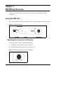
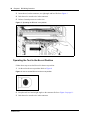
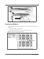
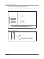
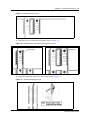
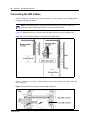
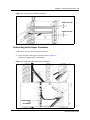
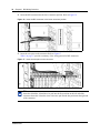
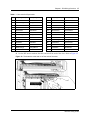
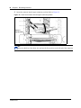
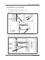
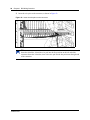
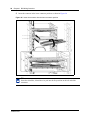
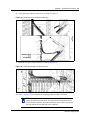
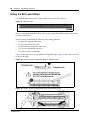
Part No. P0993134 01
Business Communications
Manager
BIX Box Wiring Guide
2
Copyright © 2002 Nortel Networks
All rights reserved. September 2002.
The information in this document is subject to change without notice. The statements, configurations, technical data, and
recommendations in this document are believed to be accurate and reliable, but are presented without express or implied
warranty. Users must take full responsibility for their applications of any products specified in this document. The
information in this document is proprietary to Nortel Networks NA Inc.
Trademarks
NORTEL NETWORKS is a trademark of Nortel Networks.
Microsoft, MS, MS-DOS, Windows, and Windows NT are registered trademarks of Microsoft Corporation.
All other trademarks and registered trademarks are the property of their respective owners.
P0993134 01
3
Contents
Preface . . . . . . . . . . . . . . . . . . . . . . . . . . . . . . . . . . . . . . . . . . . . . . . . . . . . . . . 7
Regulations . . . . . . . . . . . . . . . . . . . . . . . . . . . . . . . . . . . . . . . . . . . . . . . . . . . . . . . . . . 7
Related Publications . . . . . . . . . . . . . . . . . . . . . . . . . . . . . . . . . . . . . . . . . . . . . . . . . . . 7
Chapter 1
BIX Wiring Overview . . . . . . . . . . . . . . . . . . . . . . . . . . . . . . . . . . . . . . . . . . . . 9
Using the BIX Tool . . . . . . . . . . . . . . . . . . . . . . . . . . . . . . . . . . . . . . . . . . . . . . . . . . . . . 9
Operating the Tool in the Cut Position . . . . . . . . . . . . . . . . . . . . . . . . . . . . . . . . . . . 9
Operating the Tool in the No-cut Position . . . . . . . . . . . . . . . . . . . . . . . . . . . . . . . 10
Installing the BIX Mount . . . . . . . . . . . . . . . . . . . . . . . . . . . . . . . . . . . . . . . . . . . . . . . . 11
Connecting the BIX Cables . . . . . . . . . . . . . . . . . . . . . . . . . . . . . . . . . . . . . . . . . . . . . 14
Connecting to the Upper Connector . . . . . . . . . . . . . . . . . . . . . . . . . . . . . . . . . . . 15
Connecting to the Lower Connector . . . . . . . . . . . . . . . . . . . . . . . . . . . . . . . . . . . 19
Using the BIX Label Strips . . . . . . . . . . . . . . . . . . . . . . . . . . . . . . . . . . . . . . . . . . . . . . 24
BIX Box Wiring Guide
4
Contents
Figures
Figure 1
QTBIX16A BIX tool . . . . . . . . . . . . . . . . . . . . . . . . . . . . . . . . . . . . . . . . . . 9
Figure 2
How to set the BIX tool to the cut position . . . . . . . . . . . . . . . . . . . . . . . . . 9
Figure 3
Operating the BIX tool in cut position . . . . . . . . . . . . . . . . . . . . . . . . . . . . 10
Figure 4
How to set the BIX tool to the no cut position. . . . . . . . . . . . . . . . . . . . . . 10
Figure 5
Operating the BIX tool in no cut position . . . . . . . . . . . . . . . . . . . . . . . . . 11
Figure 6
Example of a single channel installation . . . . . . . . . . . . . . . . . . . . . . . . . 11
Figure 7
Clearances required for installing BIX panels on the wall . . . . . . . . . . . . 12
Figure 8
Install the first mount . . . . . . . . . . . . . . . . . . . . . . . . . . . . . . . . . . . . . . . . 12
Figure 9
Install the second mount . . . . . . . . . . . . . . . . . . . . . . . . . . . . . . . . . . . . . 13
Figure 10
Install the third mount and fourth (optional) mount . . . . . . . . . . . . . . . . . . 13
Figure 11
Install the distribution rings . . . . . . . . . . . . . . . . . . . . . . . . . . . . . . . . . . . . 13
Figure 12
Route incoming cables for connection on the BIX panel . . . . . . . . . . . . . 14
Figure 13
How to insert the upper and lower BIX connectors . . . . . . . . . . . . . . . . . 14
Figure 14
How to remove the BIX connectors . . . . . . . . . . . . . . . . . . . . . . . . . . . . . 15
Figure 15
Fasten the cable to the upper connector . . . . . . . . . . . . . . . . . . . . . . . . . 15
Figure 16
Insert the BIX connector in the lower connector position . . . . . . . . . . . . . 16
Figure 17
Insert the wire pairs on the connector . . . . . . . . . . . . . . . . . . . . . . . . . . . 16
Figure 18
Terminate the cable and cut off the ends of the wires . . . . . . . . . . . . . . . 17
Figure 19
Insert the connector into the upper connector position . . . . . . . . . . . . . . 18
Figure 20
Fasten the lower connector cable wire . . . . . . . . . . . . . . . . . . . . . . . . . . . 19
Figure 21
Connecting to the upper connector pair in the No. 2 position . . . . . . . . . 19
Figure 22
Insert the wire pairs on the connector . . . . . . . . . . . . . . . . . . . . . . . . . . . 20
Figure 23
Terminate the cable and cut off the ends of the wires . . . . . . . . . . . . . . . 21
Figure 24
Insert the connector into the lower connector position . . . . . . . . . . . . . . . 22
Figure 25
Fasten the upper connector cable wire . . . . . . . . . . . . . . . . . . . . . . . . . . 23
Figure 26
Insert the wire pairs on the connector . . . . . . . . . . . . . . . . . . . . . . . . . . . 23
Figure 27
BIX label strips . . . . . . . . . . . . . . . . . . . . . . . . . . . . . . . . . . . . . . . . . . . . . 24
Figure 28
How to install the designation strips on the BIX mount . . . . . . . . . . . . . . 24
Figure 29
How to remove the designation strips from the BIX mount . . . . . . . . . . . 24
P0993134 01
Contents
5
Tables
Table 1
Color code for 25 pair cable . . . . . . . . . . . . . . . . . . . . . . . . . . . . . . . . . . . 17
BIX Box Wiring Guide
6
Contents
P0993134 01
7
Preface
This guide provides a pictoral overview about how to install a BIX box and wire it for the internal
and external (trunks) hard wire connections for the Business Communications Manager.
To use this guide, you must:
•
•
be a Nortel Networks installer with Business Communications Manager certification
know basic Nortel Networks terminology
Regulations
Refer to the Business Communications Manager Installation and Maintenance Guide for the
regulatory information that affects the Business Communications Manager hardware, software,
and configuration.
Related Publications
For more information about the Business Communications Manager and equipment installation,
refer to:
•
•
Business Communications Manager Installation and Maintenance Guide describes how to
install the Business Communications Manager hardware, including the wiring for the media
bay modules.
Business Communications Manager Programming Operations Guide describes how to
program the Business Communications Manager equipment.
BIX Box Wiring Guide
8
Preface
P0993134 01
Chapter 1
BIX Wiring Overview
This guide provides a process and descriptions about wiring and labelling the BIX
connectors.
Using the BIX Tool
This section describes the BIX tool and how to use it. Figure 1 shows a picture of the tool
Figure 1 QTBIX16A BIX tool
Operating the Tool in the Cut Position
Follow these steps to use the tool in the cut position.
1
Set the tool to the cut position. Refer to Figure 2.
2
Point the black blade towards the wire end to cut off.
Figure 2 How to set the BIX tool to the cut position
BIX Box Wiring Guide
10
Chapter 1 BIX Wiring Overview
3
Insert the tool, on the connector, at a right angle and level. Refer to Figure 3
4
Push the tool to seat the wire in the connector.
5
Release forward pressure to cut the wire.
Figure 3 Operating the BIX tool in cut position
Operating the Tool in the No-cut Position
Follow these steps to use the Bix tool in the no-cut position:
1
Set the tool to the no-cut position. Refer to Figure 4.
Figure 4 How to set the BIX tool to the no cut position.
2
Keep the tool level and at right angles to the connector. Refer to Figure 5 on page 11.
3
Push the tool to seat the wire in the connector.
P0993134 01
11
Figure 5 Operating the BIX tool in no cut position
Installing the BIX Mount
This section describes a single-channel installation. Figure 6 provides a diagram of this type of
configuration.
•
•
Use the upper field for the equipment side.
Use the lower field for the house side or telephone/switching center side.
Figure 6 Example of a single channel installation
BIX Box Wiring Guide
12
Chapter 1 BIX Wiring Overview
These steps describe how to mount a single-channel BIX block.
1
Draw vertical and horizontal reference lines on the wall mounting surface. Refer to Figure 7.
Figure 7 Clearances required for installing BIX panels on the wall
2
Install the screws to install the bottom mounts. Refer to Figure 8 to Figure 9.
Figure 8 Install the first mount
P0993134 01
Chapter 1 BIX Wiring Overview
13
Figure 9 Install the second mount
3
Install the screws to install the top mounts. Refer to Figure 10.
Figure 10 Install the third mount and fourth (optional) mount
Third mount
4
Fourth mount
(optional)
Install the distribution rings above the mounts. Refer to Figure 11.
Figure 11 Install the distribution rings
BIX Box Wiring Guide
14
Chapter 1 BIX Wiring Overview
Connecting the BIX Cables
Once the mounts are installed, set up the cable pathways. Ensure that the cable bending radius
complies with the note below.
Note: The bending radius is four times the cable diameter for four-pair cables. For
multi-pair cables, the bending radius is 10 times the cable diameter.
Figure 12 demonstrates how to route the cable into the mount at the correct bending radius.
Figure 12 Route incoming cables for connection on the BIX panel
Figure 13 and Figure 14 on page 15 demonstrate how to insert and remove the upper and lower
BIX connectors.
Figure 13 How to insert the upper and lower BIX connectors
P0993134 01
Chapter 1 BIX Wiring Overview
15
Figure 14 How to remove the BIX connectors
Connecting to the Upper Connector
Follow these steps to connect the upper connector.
1
Fasten the cable to the upper connector. Refer to Figure 15.
Ensure the bending radius is maintained.
Figure 15 Fasten the cable to the upper connector
BIX Box Wiring Guide
16
Chapter 1 BIX Wiring Overview
2
Insert the BIX connector into the lower connector position. Refer to Figure 16.
Figure 16 Insert the BIX connector in the lower connector position
3
Insert the wire pairs on the connector. Refer to Figure 17.
Table 1 on page 17 provides a summary of the wiring pattern for BIX connectors
Figure 17 Insert the wire pairs on the connector
TIP:
Insert the white/blue, blue/white wire pair into the first position on the left end of the
connector. Insert the violet/slate, slate/violet wire pair into the last position on the right end
of the connector.
P0993134 01
Chapter 1 BIX Wiring Overview
17
Table 1 Color code for 25 pair cable
Pair
TIP (Body/Band)
RING (Body/Band)
Pair
TIP (Body/Band)
RING (Body/Band)
1
White/Blue
Blue/White
14
Black/Brown
Brown/Black
2
White/Orange
Orange/White
15
Black/Slate
Slate/Black
3
White/Green
Green/White
16
Yellow/Blue
Blue/Yellow
4
White/Brown
Brown/White
17
Yellow/Orange
Orange/Yellow
5
White/Slate
Slate/White
18
Yellow/Green
Green/Yellow
6
Red/Blue
Blue/Red
19
Yellow/Brown
Brown/Yellow
7
Red/Orange
Orange/Red
20
Yellow/Slate
Slate/Yellow
8
Red/Green
Green/Red
21
Violet/Blue
Blue/Violet
9
Red/Brown
Brown/Red
22
Violet/Orange
Orange/Violet
10
Red/Slate
Slate/Red
23
Violet/Green
Green/Violet
11
Black/Blue
Blue/Black
24
Violet/Brown
Brown/Violet
12
Black/Orange
Orange/Black
25
Violet/Slate
Slate/Violet
13
Black/Green
Green/Black
4
Use the BIX tool to terminate the cable and cut off the ends of the wires. Refer to Figure 18.
Figure 18 Terminate the cable and cut off the ends of the wires
BIX Box Wiring Guide
18
Chapter 1 BIX Wiring Overview
5
Insert the connector into the upper connector position. Refer to Figure 19.
Figure 19 Insert the connector into the upper connector position
Connector
properly seated
TIP:
Insert the white/blue, blue/white wire pair into the first position on the left end of the connector.
P0993134 01
Chapter 1 BIX Wiring Overview
19
Connecting to the Lower Connector
Follow these steps to install the lower connector.
1
Fasten the lower connector cable wire. Refer to Figure 20.
Figure 20 Fasten the lower connector cable wire
Lower
connector
2
Connect the upper connector pair in the No. 2 position, as shown in Figure 21.
Figure 21 Connecting to the upper connector pair in the No. 2 position
BIX Box Wiring Guide
20
Chapter 1 BIX Wiring Overview
3
Insert the wire pairs on the connector, as shown in Figure 22.
Figure 22 Insert the wire pairs on the connector
TIP:
Insert the white/blue, blue/white wire pair into the first position on the left end of the
connector. Insert the violet/slate, slate/violet wire pair into the last position on the right end
of the connector.
P0993134 01
Chapter 1 BIX Wiring Overview
4
21
Terminate the cable and cut off the ends of the wires, as shown in Figure 23.
Figure 23 Terminate the cable and cut off the ends of the wires
Note: Using the wire retainer shown at the bottom of the figure is optional.
BIX Box Wiring Guide
22
Chapter 1 BIX Wiring Overview
5
Insert the connector in the lower connector position, as shown in Figure 24.
Figure 24 Insert the connector into the lower connector position
TIP:
Insert the white/blue, blue/white wire pair into the first position on the left end of the
connector.
P0993134 01
Chapter 1 BIX Wiring Overview
6
23
Fasten the upper connector cable wire, as shown in Figure 25.
Figure 25 Fasten the upper connector cable wire
7
Insert the wire pairs on the connector, as shown in Figure 26.
Figure 26 Insert the wire pairs on the connector
See Table 1 on page 17 for a summary of the wiring pattern for BIX connectors
TIP:
Insert the white/blue, blue/white wire pair into the first position on the
left end of the connector. Insert the violet/slate, slate/violet wire pair into
the last position on the right end of the connector.
BIX Box Wiring Guide
24
Chapter 1 BIX Wiring Overview
Using the BIX Label Strips
Use the blank label strips to label wiring on BIX connectors. Refer to Figure 27.
Figure 27 BIX label strips
Before you install the blank label strips, refer to your work order/installation plan for the correct
position of blank labels.
Nortel Networks recommends the following color-coding guidelines:
•
•
•
•
•
Use blue for telephone connections
Use blue or green for riser cable
Use green for incoming trunk connections
Use silver for multiplying connectors
Use yellow for other connections
Figure 28 shows the correct way to install the designation strips. Figure 29 shows the correct way
to remove the strips.
Figure 28 How to install the designation strips on the BIX mount
Figure 29 How to remove the designation strips from the BIX mount
P0993134 01