1
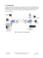
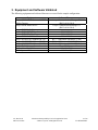
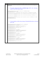
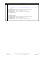
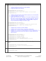
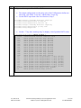
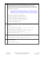
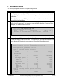
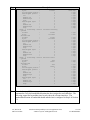
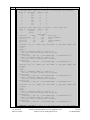
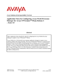
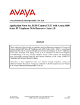
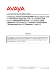
Avaya Solution & Interoperability Test Lab
Configuring Juniper Networks J4300 and Cisco 1841 Routers
to use compressed Real Time Protocol over Point-to-Point
Protocol to Support an Avaya IP Telephony Infrastructure –
Issue 1.0
Abstract
These Application Notes describe the steps for configuring Juniper Networks J4300 and Cisco
Systems 1841 routers to use compressed RTP (cRTP) over a Point-to-Point Protocol (PPP)
connection to support an Avaya IP Telephony infrastructure. The Avaya IP Telephony
infrastructure consists of Avaya Media Server, Avaya Media Gateways, and Avaya IP
Telephones. The Juniper Networks and Cisco routers will perform header compression for all
RTP packets traversing over the PPP connection to minimize overhead and increasing
available bandwidth.
AL; Reviewed:
SPOC 8/16/2006
Solution & Interoperability Test Lab Application Notes
©2006 Avaya Inc. All Rights Reserved.
1 of 20
J-C-cRTP-PPP.doc
1. Introduction
RTP packets generated by Voice over IP (VoIP) telephony are typically small in size ranging in tens
of bytes per packet. Various headers such as IP (20 bytes) and UDP (8 bytes) are then added onto
each packet before transmission. Because of the relative small packet size of RTP packet, the IP and
UDP headers compose a large percentage of overhead in each frame. For RTP packets that traverse
a Wide Area Network (WAN) that has a small bandwidth, The IP and UDP headers represents an
opportunity for bandwidth saving that could otherwise be used for other traffic or additional VoIP
calls. The compression of RTP header is known as cRTP for short.
Figure 1, illustrate the configuration used in these Application Notes. Two separate IP networks,
one in each location are connected together by a Juniper Networks J4300 and Cisco 1841 routers
over a PPP connection. Each location contains an Avaya Media Server, an Avaya Media Gateway,
and Avaya IP Telephones. A H.323 trunk configured between the two Avaya Media Servers
running Avaya Communication Manager allows calls to be routed between the two systems. Both
the Juniper Networks J4300 and Cisco 1841 routers are configured to perform RTP header
compression for all RTP packets traversing over the PPP connection. Both routers are configured to
prioritize VoIP traffic based on DiffServ Code Point (DSCP) information encoded in each VoIP
packet. Bandwidth allocation was set on all interfaces shown to guarantee that the necessary
bandwidth is reserved for VoIP traffic in the event of network congestion.
AL; Reviewed:
SPOC 8/16/2006
Solution & Interoperability Test Lab Application Notes
©2006 Avaya Inc. All Rights Reserved.
2 of 20
J-C-cRTP-PPP.doc
2. Configuration
Telephones with the extension range of 3xxxx are registered with the Avaya S8300 Media Server on
the right side of the figure, and telephones with extension range of 2xxxx are registered with Avaya
S8500 Media Server on the left side of the figure. A uniform dial plan and an H.323 IP trunk was
used to route calls between the two Avaya Media Servers. IP addresses for all the devices are
statically administered.
Figure 1: Sample Network Configuration
AL; Reviewed:
SPOC 8/16/2006
Solution & Interoperability Test Lab Application Notes
©2006 Avaya Inc. All Rights Reserved.
3 of 20
J-C-cRTP-PPP.doc
3. Equipment and Software Validated
The following equipment and software/firmware were used for the sample configuration:
Equipment
Avaya S8300 Media Server with G350
Media Gateway
Avaya S8500 Media Server
Avaya G650 Media Gateway
TN2312BP IPSI
TN799DP C-LAN
TN2302AP IP MedPro
Avaya 4602SW IP Telephone (H.323)
Avaya 4610SW IP Telephone (H.323)
Avaya 4620SW IP Telephone (H.323)
Avaya IP Softphone
Juniper Networks J4300 router
Cisco Systems 1841 router
AL; Reviewed:
SPOC 8/16/2006
Software/Firmware
Avaya Communication Manager 3.1
(R013x.01.0.626.0)
Avaya Communication Manager 3.1
(R013x.01.0.626.0)
HW03 FW009
HW01 FW015
HW18 FW108
R2.3 – Application (a02d01b2_3.bin)
R2.3 – Application (a10d01b2_3.bin)
R.2.3 – Application (a20d01b2_3.bin)
5.24.8
JUNOS 7.6R2.6
IOS 12.3(8)T6
Solution & Interoperability Test Lab Application Notes
©2006 Avaya Inc. All Rights Reserved.
4 of 20
J-C-cRTP-PPP.doc
4. Avaya Communication Manager
There is no unique configuration required in Avaya Communication Manager to support compressed
RTP (cRTP) or any feature(s) mentioned in this document. For detailed information on the
Installation, Maintenance, and Configuration of Avaya Communication Manager, please consult
reference [5], [2], and [3].
Step
Description
Below is the output from display ip-network-region from the SAT terminal of Avaya
1.
Communication Manager. This display shows the MEDIA PARAMETERS and
DIFFSERV/TOS PARAMETERS information configured in Avaya Communication
Manager.
The MEDIA PARAMETERS information will be needed in Section 5.1 Step 6 and the
DIFFSERV/TOS PARAMETERS information will be in Section 5.1 Step 3 and
Section 5.2 Step 2.
Note: The Call Control PHB Value of 34 is equivalent to 100010 in binary.
The Audio PHB Value of 46 is equivalent to 101110 in binary.
display ip-network-region 1
19
Page
1 of
IP NETWORK REGION
Region: 1
Location:
Authoritative Domain:
Name:
MEDIA PARAMETERS
Intra-region IP-IP Direct Audio: yes
Codec Set: 1
Inter-region IP-IP Direct Audio: yes
UDP Port Min: 2048
IP Audio Hairpinning? n
UDP Port Max: 3029
DIFFSERV/TOS PARAMETERS
RTCP Reporting Enabled? y
Call Control PHB Value: 34
RTCP MONITOR SERVER PARAMETERS
Audio PHB Value: 46
Use Default Server Parameters? y
Video PHB Value: 26
802.1P/Q PARAMETERS
Call Control 802.1p Priority: 6
Audio 802.1p Priority: 6
Video 802.1p Priority: 5
AUDIO RESOURCE RESERVATION PARAMETERS
H.323 IP ENDPOINTS
RSVP Enabled? n
H.323 Link Bounce Recovery? y
Idle Traffic Interval (sec): 20
Keep-Alive Interval (sec): 5
Keep-Alive Count: 5
AL; Reviewed:
SPOC 8/16/2006
Solution & Interoperability Test Lab Application Notes
©2006 Avaya Inc. All Rights Reserved.
5 of 20
J-C-cRTP-PPP.doc
5. Configure the Networks Routers
The following sections describe steps for configuring the Juniper Networks J4300 and Cisco
Systems 1841 routers in the sample configuration.
5.1. Configure the Juniper Networks J4300 router.
This section shows the necessary steps in configuring the Juniper Networks J4300 router as shown in
the sample network. The following steps use the Command Line Interface (CLI) of the J4300 router.
Unless other wise specified, all routers configuration are based on Juniper Networks
recommendation.
Step
Description
Connect
to
the
J4300.
Log
in
using
the
appropriate Login ID and Password.
1.
login:
Password:
The following prompt will appears after successful log in.
interop@J4300>
2.
Enter configuration mode by typing in edit at the prompt.
interop@J4300> edit
interop@J4300#
AL; Reviewed:
SPOC 8/16/2006
Solution & Interoperability Test Lab Application Notes
©2006 Avaya Inc. All Rights Reserved.
6 of 20
J-C-cRTP-PPP.doc
Step
Description
Configure the code-point-aliases and classifier for Avaya VoIP traffic.
3.
•
•
•
The alias helps identify the binary DSCP setting by giving it a name.
The sample network uses the name “avaya-rtp” to denote the dscp binary bit
101110 for media traffic. This is equivalent to the decimal vale of 46 set in
Avaya Communication Manager for RTP Media in Section 4, Step 1.
The sample network uses the name “avaya-sig” to denote dscp binary bit 100010
for signaling traffic. This is equivalent to the decimal vale of 34 set in Avaya
Communication Manager for signaling in Section 4, Step 1.
interop@J4300#
interop@J4300#
interop@J4300#
interop@J4300#
•
•
•
edit class-of-service code-point-aliases
set dscp avaya-rtp 101110
set dscp avaya-sig 100010
exit
Define a classifier called “Avaya-voip”.
The classifier “Avaya-voip” defines the forwarding characteristic of the router
based on traffic types.
The sample configuration is configured to use expedited-forwarding with low
loss-priority for “avaya-rtp”, and assured-forwarding with low loss-priority for
“avaya-sig”.
interop@J4300# edit class-of-service classifiers
interop@J4300# edit dscp Avaya-voip
interop@J4300# set forwarding-class expedited-forwarding loss-priority
low code-points avaya-rtp
interop@J4300# set forwarding-class assured-forwarding loss-priority
low code-points avaya-sig
interop@J4300# exit
AL; Reviewed:
SPOC 8/16/2006
Solution & Interoperability Test Lab Application Notes
©2006 Avaya Inc. All Rights Reserved.
7 of 20
J-C-cRTP-PPP.doc
Step
Description
Configure the scheduler to specify how much bandwidth to allocate for each type of
4.
traffic queue.
•
The sample configuration defines a scheduler-maps called “voip”, and assign a
name for each of the 4 queues types.
interop@J4300#
interop@J4300#
interop@J4300#
interop@J4300#
interop@J4300#
interop@J4300#
interop@J4300#
interop@J4300#
•
edit class-of-service scheduler-maps
edit voip
set forwarding-class best-effort scheduler be-sched
set forwarding-class expedited-forwarding scheduler efsched
set forwarding-class assured-forwarding scheduler afsched
set forwarding-class network-control scheduler nc-sched
exit
exit
Use the scheduler to define the percentage of bandwidth allocation to each traffic
queue type.
interop@J4300#
interop@J4300#
interop@J4300#
interop@J4300#
interop@J4300#
interop@J4300#
interop@J4300#
interop@J4300#
interop@J4300#
interop@J4300#
interop@J4300#
interop@J4300#
interop@J4300#
interop@J4300#
interop@J4300#
interop@J4300#
interop@J4300#
interop@J4300#
interop@J4300#
interop@J4300#
interop@J4300#
AL; Reviewed:
SPOC 8/16/2006
edit class-of-service schedulers
edit be-sched
set transmit-rate percent 10
set buffer-size percent 10
set priority low
exit
edit ef-sched
set transmit-rate percent 80
set buffer-size percent 80
set priority high
exit
edit af-sched
set transmit-rate percent 5
set buffer-size percent 5
set priority high
exit
edit nc-sched
set transmit-rate percent 5
set buffer-size percent 5
set priority high
exit
Solution & Interoperability Test Lab Application Notes
©2006 Avaya Inc. All Rights Reserved.
8 of 20
J-C-cRTP-PPP.doc
Step
Description
Assign the scheduler-map to each interface.
5.
•
Configure each interface with scheduler-map voip using the classifier defined
above.
interop@J4300#
interop@J4300#
interop@J4300#
interop@J4300#
interop@J4300#
interop@J4300#
interop@J4300#
interop@J4300#
interop@J4300#
interop@J4300#
interop@J4300#
interop@J4300#
AL; Reviewed:
SPOC 8/16/2006
edit class-of-service interfaces fe-0/0/1
set unit 0 scheduler-map voip
set unit 0 classifiers dscp avaya-voip
exit
edit class-of-service interfaces ls-0/0/0
set unit 0 scheduler-map voip
set unit 0 classifiers dscp avaya-voip
exit
edit class-of-service interfaces t1-2/0/0
set unit 0 scheduler-map voip
set unit 0 classifiers dscp avaya-voip
exit
Solution & Interoperability Test Lab Application Notes
©2006 Avaya Inc. All Rights Reserved.
9 of 20
J-C-cRTP-PPP.doc
Step
Description
Configure the Ethernet and T1 interfaces.
6.
•
•
Configure the Ethernet interface to use the scheduler.
Assign an IP address to the interface.
interop@J4300#
interop@J4300#
interop@J4300#
interop@J4300#
•
•
•
Configure the logical interface for the WAN connection to use the scheduler.
Assign an IP address to the interface.
Specify the RTP traffic to be compressed. The sample configuration defines
RTP traffic with port UDP range 2048 to 3029 to be compressed. This port
range needs to match to UDP Port Min and UDP Port Max configured in
Avaya Communication Manager in Section 4, Step 1.
interop@J4300#
interop@J4300#
interop@J4300#
interop@J4300#
interop@J4300#
•
•
•
edit int ls-0/0/0
set per-unit-scheduler
set unit 0 compression rtp port min 2048 max 3029
set unit 0 family inet 192.168.1.1/30
exit
Configure the T1 interface to use the scheduler.
Configure the T1 interface timing, encapsulation, and timeslots.
Configure the T1 interface to use logical interface ls-0/0/0.0 defined above. An
IP address is not necessary because an IP address is already defined for the
logical interface.
interop@J4300#
interop@J4300#
interop@J4300#
interop@J4300#
interop@J4300#
interop@J4300#
interop@J4300#
7.
edit int fe-0/0/1
set per-unit-scheduler
set unit 0 family inet address 172.28.20.254/24
exit
edit int t1-2/0/0
set per-unit-scheduler
set clocking internal
set encapsulation ppp
set t1-options timeslots 1-24
set unit 0 compression-device ls-0/0/0.0
exit
Configure the routing options for the J4300 router. The sample configuration uses static
routes.
interop@J4300# edit routing-options static
interop@J4300# route 172.28.10.0/24 next-hop 192.168.1.1
interop@J4300# exit
8.
Save the changes.
interop@J4300# commit
AL; Reviewed:
SPOC 8/16/2006
Solution & Interoperability Test Lab Application Notes
©2006 Avaya Inc. All Rights Reserved.
10 of 20
J-C-cRTP-PPP.doc
5.2. Configure the Cisco System 1841 router
This section shows the necessary steps in configuring the Cisco 1841 router as shown in the sample
network. The following steps use the Command Line Interface (CLI) of the Cisco 1841 router.
Step
Description
Connect to the Cisco 1841 router. Log in using the appropriate Password. Enter into
1.
enable mode using the appropriate enabled password. Enter the configuration mode by
typing in “configure terminal”
Password:
Cisco1841>en
Password:
Cisco1841# configure terminal
Cisco1841(config)#
AL; Reviewed:
SPOC 8/16/2006
Solution & Interoperability Test Lab Application Notes
©2006 Avaya Inc. All Rights Reserved.
11 of 20
J-C-cRTP-PPP.doc
Step
Description
Configure a class-map to define VoIP traffic.
2.
•
•
The sample configuration uses the dscp value of the VoIP packet to define two
class-map. One called “avaya-rtp”, and the other “avaya-sig”.
Use the DSCP equivalent value set in Section 4, Step 1.
Cisco1841(config)# class-map match-any avaya-rtp
Cisco1841(config-cmap)# match ip dscp ef
Cisco1841(config-cmap)# match protocol rtp
Cisco1841(config)# class-map match-all avaya-sig
Cisco1841(config-cmap)# match ip dscp af41
Cisco1841(config-cmap)# exit
•
Use the “?” key after “match ip dscp” to display a list of possible DSCP values.
Cisco1841(config-cmap)# match ip dscp ?
<0-63>
Differentiated services codepoint value
af11
Match packets with AF11 dscp (001010)
af12
Match packets with AF12 dscp (001100)
af13
Match packets with AF13 dscp (001110)
af21
Match packets with AF21 dscp (010010)
af22
Match packets with AF22 dscp (010100)
af23
Match packets with AF23 dscp (010110)
af31
Match packets with AF31 dscp (011010)
af32
Match packets with AF32 dscp (011100)
af33
Match packets with AF33 dscp (011110)
af41
Match packets with AF41 dscp (100010)
af42
Match packets with AF42 dscp (100100)
af43
Match packets with AF43 dscp (100110)
cs1
Match packets with CS1(precedence 1) dscp
cs2
Match packets with CS2(precedence 2) dscp
cs3
Match packets with CS3(precedence 3) dscp
cs4
Match packets with CS4(precedence 4) dscp
cs5
Match packets with CS5(precedence 5) dscp
cs6
Match packets with CS6(precedence 6) dscp
cs7
Match packets with CS7(precedence 7) dscp
default Match packets with default dscp (000000)
ef
Match packets with EF dscp (101110)
AL; Reviewed:
SPOC 8/16/2006
Solution & Interoperability Test Lab Application Notes
©2006 Avaya Inc. All Rights Reserved.
(001000)
(010000)
(011000)
(100000)
(101000)
(110000)
(111000)
12 of 20
J-C-cRTP-PPP.doc
Step
Description
Define a policy-map to perform bandwidth allocation. The sample network defined a
3.
policy-map called avaya-voip with 5% bandwidth allocated for signaling, 70%
bandwidth allocated for RTP, and the remaining bandwidth for the rest of the traffic.
70% is the maximum bandwidth allocation that can be defined for a particular type of
traffic in the Cisco 1841 router.
•
Compress RTP must be enabled using a policy map. The alternative method of
enabling ip rtp header compression at the interface level will not interoperate
with the Juniper router as it also enables TCP header compression automatically.
Cisco1841(config)# policy-map avaya-voip
Cisco1841(config-pmap)# class avaya-sig
Cisco1841(config-pmap-c)# bandwidth percent 5
Cisco1841(config-pmap-c)# class avaya-rtp
Cisco1841(config-pmap-c)# bandwidth percent 70
Cisco1841(config-pmap-c)# compress header ip rtp
Cisco1841(config-pmap-c)# class class-default
Cisco1841(config-pmap-c)# fair-queue
Cisco1841(config-pmap-c)# exit
Cisco1841(config-pmap-c)# exit
4.
Configure the Ethernet and T1 interfaces. Apply the policy-map avaya-voip to the serial
interface.
Cisco1841(config)# int fa0/1
Cisco1841(config-if)# ip address 172.28.10.254 255.255.255.0
Cisco1841(config-if)# Serial0/0/0
Cisco1841(config-if)# ip address 192.168.1.2 255.255.255.252
Cisco1841(config-if)# service-policy output avaya-voip
Cisco1841(config-if)# encapsulation ppp
Cisco1841(config-if)# service-module t1 timeslots 1-24
Cisco1841(config-if)# exit
5.
Configure routing. Static routes were used in the sample configuration.
Cisco1841(config)# ip route 172.28.20.0 255.255.255.0 192.168.1.1
Cisco1841(config)# ip default-gateway 192.168.1.1
6.
Save the configuration.
Cisco1841(config)# exit
Cisco1841(config)# write mem
AL; Reviewed:
SPOC 8/16/2006
Solution & Interoperability Test Lab Application Notes
©2006 Avaya Inc. All Rights Reserved.
13 of 20
J-C-cRTP-PPP.doc
6. Verification Steps
The following steps may be used to verify the configuration.
Step
Description
Verify network connectivity using “ping” from the PC. All network devices including
1.
Avaya IP Telephones should be reachable including network devices across the WAN
connection.
2.
3.
Place calls between Avaya IP Telephones across the two IP networks. Verify calls can
be established and maintained.
From the Juniper J4300 router, use the show service crtp flow command to verify that
traffic is being compressed. For an active phone call, there should be at least two flows
displayed, one transmit and one receive.
interop@J4300> show services crtp flows
Interface: Interface: ls-0/0/0.0
Flow
Source
Destination
Transmit 172.28.20.128:2300 172.28.10.128:2594
Receive
172.28.10.128:2594 172.28.20.128:2300
4.
SSRC ID
1847753485
327775943
Ctx ID
7
80
From the Juniper J4300 router, use the show interface queue command to verify traffic
is being forwarded via the correct queue. The output below shows the information of an
active phone call (50pps) being sent out queue 1 (expedited-forwarding queue).
interop@J4311> show interfaces queue t1-2/0/0
Physical interface: t1-2/0/0, Enabled, Physical link is Up
Interface index: 139, SNMP ifIndex: 34
Forwarding classes: 8 supported, 8 in use
Egress queues: 8 supported, 8 in use
Queue: 0, Forwarding classes: best-effort
Queued:
Packets
:
173342
Bytes
:
40575543
Transmitted:
Packets
:
170196
Bytes
:
35897441
Tail-dropped packets :
0
RED-dropped packets :
3144
Low
:
3144
Medium-low
:
0
Medium-high
:
0
High
:
0
RED-dropped bytes
:
4675128
Low
:
4675128
Medium-low
:
0
Medium-high
:
0
High
:
0
Queue: 1, Forwarding classes: expedited-forwarding
Queued:
Packets
:
46978
Bytes
:
2361646
Transmitted:
AL; Reviewed:
SPOC 8/16/2006
Solution & Interoperability Test Lab Application Notes
©2006 Avaya Inc. All Rights Reserved.
150 pps
1784400 bps
124
1484048
0
25
25
0
0
0
300344
300344
0
0
0
pps
bps
pps
pps
pps
pps
pps
pps
bps
bps
bps
bps
bps
50 pps
25944 bps
14 of 20
J-C-cRTP-PPP.doc
Step
Description
Packets
:
46978
Bytes
:
2361646
Tail-dropped packets :
0
RED-dropped packets :
0
Low
:
0
Medium-low
:
0
Medium-high
:
0
High
:
0
RED-dropped bytes
:
0
Low
:
0
Medium-low
:
0
Medium-high
:
0
High
:
0
Queue: 2, Forwarding classes: assured-forwarding
Queued:
Packets
:
217241
Bytes
:
12011825
Transmitted:
Packets
:
217241
Bytes
:
12011825
Tail-dropped packets :
0
RED-dropped packets :
0
Low
:
0
Medium-low
:
0
Medium-high
:
0
High
:
0
RED-dropped bytes
:
0
Low
:
0
Medium-low
:
0
Medium-high
:
0
High
:
0
Queue: 3, Forwarding classes: network-control
Queued:
Packets
:
9722
Bytes
:
141217
Transmitted:
Packets
:
9722
Bytes
:
141217
Tail-dropped packets :
0
RED-dropped packets :
0
Low
:
0
Medium-low
:
0
Medium-high
:
0
High
:
0
RED-dropped bytes
:
0
Low
:
0
Medium-low
:
0
Medium-high
:
0
High
:
0
5.
50
25944
0
0
0
0
0
0
0
0
0
0
0
pps
bps
pps
pps
pps
pps
pps
pps
bps
bps
bps
bps
bps
0 pps
0 bps
0
0
0
0
0
0
0
0
0
0
0
0
0
pps
bps
pps
pps
pps
pps
pps
pps
bps
bps
bps
bps
bps
0 pps
0 bps
0
0
0
0
0
0
0
0
0
0
0
0
0
pps
bps
pps
pps
pps
pps
pps
pps
bps
bps
bps
bps
bps
From the Juniper J4300 router, use the show class-of-service forwarding-table
command to verify the bandwidth allocation has been assigned to each interface. The
following output has been abbreviated to only show the relevant interfaces. The
bandwidth allocation of bandwidth should match what is configured in Step 4 of Section
5.1.
AL; Reviewed:
SPOC 8/16/2006
Solution & Interoperability Test Lab Application Notes
©2006 Avaya Inc. All Rights Reserved.
15 of 20
J-C-cRTP-PPP.doc
Step
Description
interop@J4300> show class-of-service forwarding-table
Classifier table index: 12, # entries: 8, Table type: IPv4 precedence
Entry #
Code point
Queue #
PLP
0
000
0
0
1
001
0
1
2
010
0
0
3
011
0
1
4
100
0
0
5
101
0
1
6
110
3
0
7
111
3
1
Classifier table index: 6440, # entries: 2, Table type: DSCP
Entry #
Code point
Queue #
PLP
0
100010
2
0
1
101110
1
0
Table Index/
Interface
Index
Q num
Table type
sp-0/0/0.16383
66
12
IPv4 precedence
ls-0/0/0.0
67
6440
DSCP
fe-0/0/0.0
68
12
IPv4 precedence
fe-0/0/1.0
69
6440
DSCP
Interface: ls-0/0/0, (Index: 134,, Map index: 2,, Map type: FINAL,, Num
of queue
s: 2):
Index: 0
Entry 0 (Scheduler index: 17, Queue #: 0):
Tx rate: 0 Kb (95%), Buffer size: 95 percent
Priority low
PLP high: 1, PLP low: 1, PLP medium-high: 1, PLP medium-low: 1
Entry 1 (Scheduler index: 19, Queue #: 3):
Tx rate: 0 Kb (5%), Buffer size: 5 percent
Priority low
PLP high: 1, PLP low: 1, PLP medium-high: 1, PLP medium-low: 1
Interface: fe-0/0/1, (Index: 138,, Map index: 2,, Map type: FINAL,, Num
of queue
s: 2):
Index: 0
Entry 0 (Scheduler index: 17, Queue #: 0):
Tx rate: 0 Kb (95%), Buffer size: 95 percent
Priority low
PLP high: 1, PLP low: 1, PLP medium-high: 1, PLP medium-low: 1
Entry 1 (Scheduler index: 19, Queue #: 3):
Tx rate: 0 Kb (5%), Buffer size: 5 percent
Priority low
PLP high: 1, PLP low: 1, PLP medium-high: 1, PLP medium-low: 1
Interface: t1-2/0/0, (Index: 139,, Map index: 2,, Map type: FINAL,, Num
of queue
s: 2):
Index: 0
Entry 0 (Scheduler index: 17, Queue #: 0):
Tx rate: 0 Kb (95%), Buffer size: 95 percent
Priority low
PLP high: 1, PLP low: 1, PLP medium-high: 1, PLP medium-low: 1
Entry 1 (Scheduler index: 19, Queue #: 3):
Tx rate: 0 Kb (5%), Buffer size: 5 percent
Priority low
PLP high: 1, PLP low: 1, PLP medium-high: 1, PLP medium-low: 1
Interface: ls-0/0/0.0, (Index: 67,, Map index: 45418,, Map type: FINAL,,
AL; Reviewed:
SPOC 8/16/2006
Solution & Interoperability Test Lab Application Notes
©2006 Avaya Inc. All Rights Reserved.
16 of 20
J-C-cRTP-PPP.doc
Step
Description
Num of
queues: 4):
Index: 0
Entry 0 (Scheduler index: 13005, Queue #: 0):
Tx rate: 0 Kb (10%), Buffer size: 10 percent
Priority low
PLP high: 1, PLP low: 1, PLP medium-high: 1,
Entry 1 (Scheduler index: 62197, Queue #: 1):
Tx rate: 0 Kb (80%), Buffer size: 80 percent
Priority high
PLP high: 1, PLP low: 1, PLP medium-high: 1,
Entry 2 (Scheduler index: 62165, Queue #: 2):
Tx rate: 0 Kb (5%), Buffer size: 5 percent
Priority high
PLP high: 1, PLP low: 1, PLP medium-high: 1,
Entry 3 (Scheduler index: 45740, Queue #: 3):
Tx rate: 0 Kb (5%), Buffer size: 5 percent
Priority high
PLP high: 1, PLP low: 1, PLP medium-high: 1,
PLP medium-low: 1
PLP medium-low: 1
PLP medium-low: 1
PLP medium-low: 1
Interface: fe-0/0/1.0, (Index: 69,, Map index: 45418,, Map type:
Num of
queues: 4):
Index: 0
Entry 0 (Scheduler index: 13005, Queue #: 0):
Tx rate: 0 Kb (10%), Buffer size: 10 percent
Priority low
PLP high: 1, PLP low: 1, PLP medium-high: 1, PLP medium-low:
Entry 1 (Scheduler index: 62197, Queue #: 1):
Tx rate: 0 Kb (80%), Buffer size: 80 percent
Priority high
PLP high: 1, PLP low: 1, PLP medium-high: 1, PLP medium-low:
Entry 2 (Scheduler index: 62165, Queue #: 2):
Tx rate: 0 Kb (5%), Buffer size: 5 percent
Priority high
PLP high: 1, PLP low: 1, PLP medium-high: 1, PLP medium-low:
Entry 3 (Scheduler index: 45740, Queue #: 3):
Tx rate: 0 Kb (5%), Buffer size: 5 percent
Priority high
PLP high: 1, PLP low: 1, PLP medium-high: 1, PLP medium-low:
Interface: t1-2/0/0.0, (Index: 70,, Map index: 45418,, Map type:
Num of
queues: 4):
Index: 0
Entry 0 (Scheduler index: 13005, Queue #: 0):
Tx rate: 0 Kb (10%), Buffer size: 10 percent
Priority low
PLP high: 1, PLP low: 1, PLP medium-high: 1, PLP medium-low:
Entry 1 (Scheduler index: 62197, Queue #: 1):
Tx rate: 0 Kb (80%), Buffer size: 80 percent
Priority high
PLP high: 1, PLP low: 1, PLP medium-high: 1, PLP medium-low:
Entry 2 (Scheduler index: 62165, Queue #: 2):
Tx rate: 0 Kb (5%), Buffer size: 5 percent
Priority high
PLP high: 1, PLP low: 1, PLP medium-high: 1, PLP medium-low:
Entry 3 (Scheduler index: 45740, Queue #: 3):
Tx rate: 0 Kb (5%), Buffer size: 5 percent
Priority high
PLP high: 1, PLP low: 1, PLP medium-high: 1, PLP medium-low:
AL; Reviewed:
SPOC 8/16/2006
Solution & Interoperability Test Lab Application Notes
©2006 Avaya Inc. All Rights Reserved.
FINAL,,
1
1
1
1
FINAL,,
1
1
1
1
17 of 20
J-C-cRTP-PPP.doc
Step
Description
From the Cisco 1841 router. Use the show policy-map interface s0/0/0 output to
6.
display the interface statistics and ensure that the policy-map is configured correctly.
The bandwidth allocation of bandwidth should match what is configured in Step 3 of
Section 5.2.
Cisco1841#show policy-map interface s0/0/0 output
Serial0/0/0
Service-policy output: avaya-voip
Class-map: avaya-sig (match-all)
246 packets, 14885 bytes
5 minute offered rate 0 bps, drop rate 0 bps
Match: ip dscp af41
Queueing
Output Queue: Conversation 265
Bandwidth 5 (%)
Bandwidth 76 (kbps) Max Threshold 64 (packets)
(pkts matched/bytes matched) 190/12380
(depth/total drops/no-buffer drops) 0/0/0
Class-map: avaya-rtp (match-any)
806789 packets, 164463693 bytes
5 minute offered rate 653000 bps, drop rate 11000 bps
Match: ip dscp ef
898 packets, 182364 bytes
5 minute rate 0 bps
Match: protocol rtp
805891 packets, 164281329 bytes
5 minute rate 653000 bps
Queueing
Output Queue: Conversation 266
Bandwidth 70 (%)
Bandwidth 1075 (kbps) Max Threshold 64 (packets)
(pkts matched/bytes matched) 713569/119861698
(depth/total drops/no-buffer drops) 0/7888/0
compress:
header ip rtp
UDP/RTP (compression on, IPHC)
Sent:
806789 total, 806450 compressed,
28955604 bytes saved, 132280933 bytes sent
1.21 efficiency improvement factor
99% hit ratio, five minute miss rate 0
misses/sec, 1 max
rate 519000 bps
Class-map: class-default (match-any)
649063 packets, 710043532 bytes
5 minute offered rate 0 bps, drop rate 0 bps
Match: any
Queueing
Flow Based Fair Queueing
Maximum Number of Hashed Queues 256
(total queued/total drops/no-buffer drops) 0/237289/0
AL; Reviewed:
SPOC 8/16/2006
Solution & Interoperability Test Lab Application Notes
©2006 Avaya Inc. All Rights Reserved.
18 of 20
J-C-cRTP-PPP.doc
7. Conclusion
These Application Notes have described the administration steps required to configure RTP header
compression (cRTP) to interoperate between a Juniper Networks J4300 and a Cisco Systems 1841
router over a Point-to-Point Protocol (PPP) connection to support the Avaya IP Telephony
infrastructure. Quality of Service was implemented by the use of DSCP information for traffic
priority queue assignment, and the use of bandwidth allocation on all the interfaces. There was no
detectable difference in voice quality between VoIP traffic that has gone through header
compression to traffic that had not used header compression using both objective and subjective
testing. Basic telephone features such as Transfer, Conference, and DTMF detection continue to
function over a cRTP environment.
8. Additional References
Product documentation for Avaya products may be found at http://support.avaya.com
[1] Administrator Guide for Avaya Communication Manager, Doc # 03-300509, Issue 1, June 2005
[2] Avaya Communication Manager Advanced Administration Quick Reference, Doc # 03-300364,
Issue 2, June 2005 Release 3.0
[3] Administration for Network Connectivity for Avaya Communication Manager, Doc # 555-233504, Issue 6, May 2003
[4] Avaya IP Telephony Implementation Guide, COMPAS ID 95180, July 2005
Product documentation for Juniper Networks products may be found at http://www.Juniper.net
[5] CLI User Guide (JUNOS Internet Software for J-series, M-series, and T-series Routing
Platform) Release7.6, Part Number 530-015682-01, Revision 1
[6] JUNOS Internet Software for J-series, M-series, and T-series Routing Platforms, Class of
Service Configuration Guide Release 7.6, Part Number 530-015688-01, Revision 1
[7] JUNOS Internet Software for J-series, M-series, and T-series Routing Platforms, Network
Interfaces Configuration Guide Release 7.6, Part Number 530-015687-01, Revision 1
[8] JUNOS Internet Software for J-series, M-series, and T-series Routing Platforms, Services
Interfaces Configuration Guide Release 7.6, Part Number 530-015687-01, Revision 1
Product documentation for Cisco Systems products may be found at http://www.cisco.com
AL; Reviewed:
SPOC 8/16/2006
Solution & Interoperability Test Lab Application Notes
©2006 Avaya Inc. All Rights Reserved.
19 of 20
J-C-cRTP-PPP.doc
©2006 Avaya Inc. All Rights Reserved.
Avaya and the Avaya Logo are trademarks of Avaya Inc. All trademarks identified by ® and ™
are registered trademarks or trademarks, respectively, of Avaya Inc. All other trademarks are the
property of their respective owners. The information provided in these Application Notes is
subject to change without notice. The configurations, technical data, and recommendations
provided in these Application Notes are believed to be accurate and dependable, but are
presented without express or implied warranty. Users are responsible for their application of any
products specified in these Application Notes.
Please e-mail any questions or comments pertaining to these Application Notes along with the
full title name and filename, located in the lower right corner, directly to the Avaya Solution &
Interoperability Test Lab at [email protected]
AL; Reviewed:
SPOC 8/16/2006
Solution & Interoperability Test Lab Application Notes
©2006 Avaya Inc. All Rights Reserved.
20 of 20
J-C-cRTP-PPP.doc