1
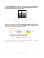
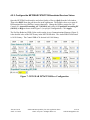
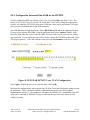
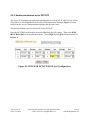
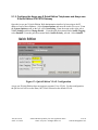
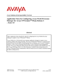
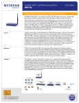
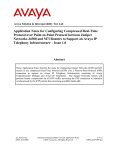
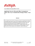
Avaya Solution & Interoperability Test Lab
Configuring NETGEAR® PROSAFE™ 8-port, 16-port and
24-port switches Supporting Power over Ethernet with
Avaya Communication Manager, Avaya one-X Quick
Edition G10 PSTN Gateway, Avaya one-X Quick Edition
Telephones and Avaya IP Telephones – Issue 1.0
Abstract
These Application Notes describe the configuration of the NETGEAR® PROSAFE™ 8 Port
FS108P, PROSAFE™ 16 Port FS116P and PROSAFE™ 24 Port FS726TP switch and Avaya
4600/9600 Series IP Telephones registered to Avaya Communication Manager and Avaya
one-X Quick Edition G10 PSTN Gateway.
JJA; Reviewed:
SPOC 5/17/2007
Solution & Interoperability Test Lab Application Notes
©2007 Avaya Inc. All Rights Reserved.
1 of 20
NETGEARAppNotes.doc
1. Introduction
Power over Ethernet (PoE) allows both power and data to be simultaneously carried over
standard Ethernet cables. PoE-enabled Ethernet switches can supply power directly to Ethernet
devices, thereby simplifying installation and removing the need for separate power supplies for
those devices.
The NETGEAR PROSAFE 8 Port (FS108P) and 16 Port (FS116P) switches provide 4/8 ports of
PoE and 4/8 ports without PoE. These unmanaged switches can be used to power Avaya
telephones successfully without configuration; however the switches do not support traffic
prioritization.
The NETGEAR PROSAFE™ 24 Port (FS726TP) switch supports 12 PoE ports, 12 additional
10/100Mbps ports without PoE, and 2 Gigabit/ small form-factor pluggable (SFP) ports without
PoE. The FS726TP provides effective traffic prioritization. A recommended configuration is
provided.
The generally available (GA) versions of all products were used for testing. Interoperability
testing was at the Avaya Solution and Interoperability Test Lab in Lincroft, NJ.
JJA; Reviewed:
SPOC 5/17/2007
Solution & Interoperability Test Lab Application Notes
©2007 Avaya Inc. All Rights Reserved.
2 of 20
NETGEARAppNotes.doc
2. Equipment and Software
The following equipment and software were used for the configuration provided:
Equipment
Avaya Media Server with Media Gateway
Avaya one-X G10 PSTN Gateway
Avaya 9610 one-X Deskphone Edition IP Telephone
Avaya 9620 one-X Deskphone Edition IP Telephone
Avaya 9630 one-X Deskphone Edition IP Telephone 24-button
module.
Avaya 9640 one-X Deskphone Edition IP Telephone with 24button module.
Avaya 9650 one-X Deskphone Edition IP Telephone with 24button module.
Avaya 4601 IP Telephone
Avaya 4601+ IP Telephone
Avaya 4602 IP Telephone
Avaya 4602SW Telephone
Avaya 4602SW+ IP Telephone
Avaya 4610SW IP Telephone
Avaya 4620SW IP Telephone (Class 3)
Avaya 4620SW IP Telephone with and without EU24
Avaya 4621SW IP Telephone with and without the EU24BL
Avaya 4622SW IP Telephone
Avaya 4625SW IP Telephone
Avaya 4610SW one-X Quick Edition IP Telephone
Avaya 4621SW one-X Quick Edition IP Telephone
NETGEAR FS108P
NETGEAR FS116P
NETGEAR FS726TP
Software/Firmware
3.1.2
3.0
1.2
1.2
1.2
1.2
1.2
2.3
2.7
2.3
2.3
2.7
2.7
2.7
2.7
2.7
2.7
2.7
7.0.2
7.0.2
N/A
N/A
1.0.2
Table 1: Avaya/NETGEAR Equipment
JJA; Reviewed:
SPOC 5/17/2007
Solution & Interoperability Test Lab Application Notes
©2007 Avaya Inc. All Rights Reserved.
3 of 20
NETGEARAppNotes.doc
2.1. Configuration of NETGEAR and Avaya equipment
.
Figure 1: Avaya/NETGEAR Network Diagram
JJA; Reviewed:
SPOC 5/17/2007
Solution & Interoperability Test Lab Application Notes
©2007 Avaya Inc. All Rights Reserved.
4 of 20
NETGEARAppNotes.doc
3. Configure the Avaya Media Server and Media Gateway
The configuration of the Avaya Media Server and Media Gateway should follow the standard
Avaya recommendations for IP Telephony [1]. In general a Quality of Service (QoS) policy
must be established across the entire IP network. The Differentiated Services (DiffServ) Code
Point (DSCP) values used by Avaya Communication Manager and by the FS726TP must be the
same.
From the System Access Terminal (SAT) enter the change ip-network-region command with
the appropriate region number specified to open an IP Network Region configuration screen. Set
the QoS DiffServ/TOS and 802.1P/Q parameters highlighted below. These are the defaults,
normally no changes will be needed.
change ip-network-region 1
19
Page
1 of
IP NETWORK REGION
Region: 1
Location: 1
Authoritative Domain: ccmcare.com
Name: AV_HUB
MEDIA PARAMETERS
Intra-region IP-IP Direct Audio: yes
Codec Set: 1
Inter-region IP-IP Direct Audio: yes
UDP Port Min: 2048
IP Audio Hairpinning? n
UDP Port Max: 3327
DIFFSERV/TOS PARAMETERS
RTCP Reporting Enabled? y
Call Control PHB Value: 26
RTCP MONITOR SERVER PARAMETERS
Audio PHB Value: 46
Use Default Server Parameters? y
Video PHB Value: 26
802.1P/Q PARAMETERS
Call Control 802.1p Priority: 6
Audio 802.1p Priority: 6
Video 802.1p Priority: 5
AUDIO RESOURCE RESERVATION PARAMETERS
H.323 IP ENDPOINTS
RSVP Enabled? n
H.323 Link Bounce Recovery? y
Idle Traffic Interval (sec): 20
Keep-Alive Interval (sec): 5
Keep-Alive Count: 5
Figure 2: Avaya QOS Configuration
JJA; Reviewed:
SPOC 5/17/2007
Solution & Interoperability Test Lab Application Notes
©2007 Avaya Inc. All Rights Reserved.
5 of 20
NETGEARAppNotes.doc
4. Configure the NETGEAR Switches
4.1. Using the NETGEAR FS108P and FS116P
The FS108P and FS116P are unmanaged switches, therefore no configuration is necessary. The
FS108P and FS116P should be connected to the LAN by an auto-negotiation enabled uplink so
that 100Mbps Full Duplex operation can be enabled. IEEE 802.1Q tags should be stripped from
packets before the packets are sent to the FS108P or the FS116P.
With the unmanaged FS108P and FS116P switches, traffic prioritization is not supported by the
NETGEAR products. It is unlikely that the ports for the Avaya Media Server or Media Gateway
would be plugged directly into these small switches. More likely the NETGEAR switches would
be attached to the LAN and the telephones would access the Avaya Media Server and Media
Gateway over the corporate LAN. Since traffic prioritization is not supported by these switches
it is important to ensure that the connection of these switches to the corporate LAN provides
adequate quality of service.
4.2. Configure the NETGEAR FS726TP
The configuration presented here only covers the Avaya IP Telephones on the PoE ports and one
Port (26) for the uplink. The administration of the remaining ports for data applications is not
covered.
JJA; Reviewed:
SPOC 5/17/2007
Solution & Interoperability Test Lab Application Notes
©2007 Avaya Inc. All Rights Reserved.
6 of 20
NETGEARAppNotes.doc
4.2.1. Configure the NETGEAR FS726TP PoE
Using a Web Browser, enter the IP address of the NETGEAR FS726TP and open the NETGEAR
web interface.
Figure 3: NETGEAR Web Interface
JJA; Reviewed:
SPOC 5/17/2007
Solution & Interoperability Test Lab Application Notes
©2007 Avaya Inc. All Rights Reserved.
7 of 20
NETGEARAppNotes.doc
Select the Power over Ethernet Configuration (POE in the left window). The default values
should be adequate, but should be verified (see Figure 4).
Figure 4: NETGEAR FS726TP PoE Configuration
If the Admin Mode is not Enable, select the port and Enable PoE from the Admin pull-down
menu. Select Apply after selecting Enable.
Figure 5: NETGEAR FS726TP PoE Enabled
JJA; Reviewed:
SPOC 5/17/2007
Solution & Interoperability Test Lab Application Notes
©2007 Avaya Inc. All Rights Reserved.
8 of 20
NETGEARAppNotes.doc
The Class field in Figure 4 refers to the IEEE 802.3af Power Classification system (Table 2).
The FS726TP measures power at the FS726TP. The Power Limit column in Figure 4 refers to
the IEEE 802.3af Maximum Power at the power source.
Class
0
1
2
3
Maximum
Power at
FS726TP
15.4W
4.0W
7.0W
15.4W
Table 2: IEEE 802.3 Power Classifications
If all of the devices are Class 2 or lower, there will be no need to assign Priority because the
total power will not exceed the Max System Power Available. If more than one of the devices
is Class 0 or Class 3, select a Priority for each port to control which ports will be shut down in
the event the powered devices exceed the Max System Power Available. In situations where a
large number of Class 0 or Class 3 devices are used, Medium priority should be assigned to one
group of the Class 0/3 devices and Low to a second group.
Figure 6: NETGEAR FS726TP PoE Priority
Assign enough Low Priority ports so that if the Max System Power Available is exceeded, the
high priority devices in the enterprise will be powered.
JJA; Reviewed:
SPOC 5/17/2007
Solution & Interoperability Test Lab Application Notes
©2007 Avaya Inc. All Rights Reserved.
9 of 20
NETGEARAppNotes.doc
4.2.2. Configure the NETGEAR FS726TP Differentiated Services Values
Open the NETGEAR web interface and select Quality of Server (QoS) from the left window.
Then select DSCP from the pull down list in the right menu. The default values are to treat all
Differentiated Services (DiffServ) entries identically. Change the DiffServ entries for Call
Control (26, Assured Forwarding, AF 31 011010) and Audio (46, Expedited Forwarding EF
(101110)) to High as shown in the Figure 3 (Avaya QoS Configuration). Click Apply.
The Per Hop Behavior (PHB) Value used in on the Avaya Communications Manager (Figure 3),
is the decimal value of the DSCP entry in the NETGEAR table. The Audio PHB of 46 decimal
is 101110 binary. The Control PHB of 26 decimal is 011010 binary.
Figure 7: NETGEAR FS726TP DiffServ Configuration
JJA; Reviewed:
SPOC 5/17/2007
Solution & Interoperability Test Lab Application Notes
©2007 Avaya Inc. All Rights Reserved.
10 of 20
NETGEARAppNotes.doc
4.2.3. Configure the Voice and Data VLAN for the FS726TP
For this configuration 135 was selected as the Voice VLAN and 100 as the Data VLAN. The
choice of 135 for the Voice VLAN and 100 for the Data VLAN can be changed as appropriate
for the LAN where the FS726TP is being used. Different values can be used but the Voice QoS
policy must be established end-to-end in the enterprise.
Select VLAN from the right hand menu. Select IEEE 802.1Q VLAN in the right hand window.
If a pop-up box appears select OK. From the pull down menu select Add new VLAN. In the
box to the right, enter the Voice VLAN ID (135). For each of the 12 PoE ports select U (Untag
egress packets). For the uplink port that will be used to connect the FS726TP to the router, select
T Tag egress packets. Leave the reminder of the ports out (Not member) of the Voice VLAN.
Figure 8: NETGEAR FS726TP Voice VLAN Configuration
Select Apply. Repeat the process to create the Data VLAN (100).
Note that this configuration is removing the tags (U) from Voice and Data packets going towards
the telephones. This is consistent with the recommendations in the Avaya IP Telephony
Implementation Guide [1]. The telephones will ignore the IEEE802.1Q. Additionally some NIC
cards can be confused by IEEE802.1Q tags so removing the tags reduces the chance of that
conflict occurring.
JJA; Reviewed:
SPOC 5/17/2007
Solution & Interoperability Test Lab Application Notes
©2007 Avaya Inc. All Rights Reserved.
11 of 20
NETGEARAppNotes.doc
4.2.4. Define the Default VLAN for untagged packets
Select PVID Setting from the pull-down menu and assign the Data VLAN (100) to each of the
PoE Ports and the uplink port as the default VLAN for those ports. Select Apply.
Figure 9: NETGEAR FS726TP PVID (Default) VLAN Configuration
Using the Data VLAN as the Default VLAN for the Avaya IP Telephones is essential to the
correct operation of a PC attached to the telephone. In most situations, the PC will not be
providing IEEE802.1Q tags and the data traffic needs to be on a separate VLAN from the Voice
traffic for prioritization.
Select VLAN 1 (Default) from the pull-down menu and remove (Not Member) the ports using
the Voice VLAN (1-12 and 26).
The DHCP services on the Data VLAN need to be configured to move telephones that have not
been correctly configured to the Voice VLAN. The administration is covered in Section 5.1.1.
JJA; Reviewed:
SPOC 5/17/2007
Solution & Interoperability Test Lab Application Notes
©2007 Avaya Inc. All Rights Reserved.
12 of 20
NETGEARAppNotes.doc
4.2.5. Enable prioritization on the FS726TP
The Avaya IP Telephones tag audio and signaling packets with an 802.1P value of 6 by default.
This value was also administered on the Avaya Communications Manager (Figure 3) so that
traffic from the Avaya Communications Manager has the same value.
This priority method is not VLAN specific on the FS726TP.
Open the NETGEAR web interface and select QoS from the left window. Then select IEEE
802.1P Based QoS from the pull-down menu. Select High from the QoS pull-down menu for
Priority 6.
Figure 10: NETGEAR FS726TP 802.1P QoS Configuration
JJA; Reviewed:
SPOC 5/17/2007
Solution & Interoperability Test Lab Application Notes
©2007 Avaya Inc. All Rights Reserved.
13 of 20
NETGEARAppNotes.doc
4.2.6. Configure the Storm Control for the FS726TP
Broadcast storms can have an extraordinarily negative impact on voice quality. From the left
window in the NETGEAR Web page select Advanced, and Storm Control. In the right
window pull-down associated with Storm Control Status, select Broadcast Only. In the pulldown associated with Threshold (bps), select 512K. Select Apply.
Figure 11: NETGEAR FS726TP Storm Control Configuration
4.2.7. Configure the FS726TP for the Avaya one-X Quick Edition Telephones
The Avaya one-X Quick Edition Telephones and G10 Gateway (QE) use multicast messages for
shared control. The telephones and the G10 Gateway are powered by PoE. The configuration
of the FS726TP needs two additional settings to support QE.
In the left hand menu of the NETGEAR Web Page select Advanced and then IGMP Snooping
Status. Disable both the IGMP Function and Block Unknown Multicast Address. Select
Apply.
Figure 12: NETGEAR FS726TP IGMP Configuration
JJA; Reviewed:
SPOC 5/17/2007
Solution & Interoperability Test Lab Application Notes
©2007 Avaya Inc. All Rights Reserved.
14 of 20
NETGEARAppNotes.doc
5. Configure the Avaya IP Telephones, Avaya one-X Quick
Edition Telephones and the Avaya one-X Quick Edition
G10 PSTN Gateway
5.1.1. Configure the Avaya IP Telephones for use with the Avaya
Communication Manager
The Avaya IP Telephones that register with Avaya Communications Manager need to have IEEE
802.1Q/P enabled.
Include the following options in the DHCP configuration for both the Data (100) and Voice
(135) VLANs:
Option 176 and 242 “L2Q=0,L2QVLAN=135”
Option 176 is used by the Avaya 46xx series IP Telephones and option 242 by the Avaya 96xx
series IP Telephones. Alternatively these can be programmed in the 46xxsettings.txt file as:
SET L2Q 0
SET L2QVLAN 135
JJA; Reviewed:
SPOC 5/17/2007
Solution & Interoperability Test Lab Application Notes
©2007 Avaya Inc. All Rights Reserved.
15 of 20
NETGEARAppNotes.doc
5.1.2. Configure the Avaya one-X Quick Edition Telephones and Avaya oneX Quick Edition G10 PSTN Gateway
Open the Avaya one-X Quick Edition Web administration interface by browsing to the IP
address of one of the telephones. Select System Options and enter the Admin Password. From
the System Options menu on the left, select Networking. From the menu on the right, select
VLAN Settings and then Change Details. From the pull-down menu labeled Audio Tagging,
select Enabled. From the pull-down menu labeled Audio Priority, select 6. Select Submit.
Figure 13: Quick Edition VLAN Configuration
Avaya one-X Quick Edition does not support a separate Voice VLAN. For this configuration,
the QE devices will be on the Data (100) VLAN selected as the default VLAN.
JJA; Reviewed:
SPOC 5/17/2007
Solution & Interoperability Test Lab Application Notes
©2007 Avaya Inc. All Rights Reserved.
16 of 20
NETGEARAppNotes.doc
6. Verification Steps
Backup the FS726TP configuration before beginning any of these steps.
6.1. Verification Steps for Avaya IP Telephones and Avaya
Communications Manager
Place phone calls between each of the Avaya IP Telephones powered by the NETGEAR
switches and trunk lines on Avaya Communication Manager. Verify that the audio quality is
acceptable. This will verify the voice network is correctly connected.
Use the Network Options on the telephone to verify that the audio statistics. Packet Loss should
be 0%. Packetization Delay should be consistent with the Codec Set selected on the Avaya
Communications Manager. One-way Network Delay and Network Jitter Delay will be
dependent on the configuration beyond the NETGEAR switches.
Plug a PC into the PC port of each of the Avaya IP Telephones and browse to an enterprise web
site. This will verify that the Data network is correctly connected.
Power cycle the NETGEAR switch. When power returns, the Avaya IP Telephones should
power up, download the parameters from the corporate DHCP/TFTP/HTTP servers and register
with Avaya Communications Manager. Repeat the above steps in the above three paragraphs to
verify that the NETGEAR switch retained the working configuration.
6.2. Verification Steps for Avaya one-X Quick Edition Telephones and
Avaya one-X G10 PSTN Gateway
Place a phone call between an Avaya one-X Quick Edition telephone and an Avaya one-X Quick
Edition G10 Gateway port to the PSTN. Verify that the audio quality is acceptable.
Power cycle the NETGEAR switch. Verify that all of the Avaya one-X Quick Edition telephone
and an Avaya one-X Quick Edition G10 Gateway power up and discover each other. Place
phone calls to verify the Avaya one-X Quick Edition telephone and an Avaya one-X Quick
Edition G10 Gateway are operational.
Plug a PC into the PC port of one of the QE telephones and browse the web address of one of the
Avaya one-X Quick Edition telephones. Follow the steps in Section 4.2.1 to verify that the
VLAN settings have been retained.
JJA; Reviewed:
SPOC 5/17/2007
Solution & Interoperability Test Lab Application Notes
©2007 Avaya Inc. All Rights Reserved.
17 of 20
NETGEARAppNotes.doc
6.3. Verification Steps for the FS726TP PoE
After power cycling the FS726TP, attach a PC to the PC port of one of the Avaya IP Telephones.
Open a web browser with the IP address of the FS726TP. Select POE from the left hand menu
and verify that all of the Avaya IP Telephones are being powered as expected (Figure 4).
Select Port Configuration from the left window of the FS726TP Web page and verify that the
speed and duplex of all the powered Avaya IP Telephone ports is 100Mbps/Full. Verify that the
speed and duplex for Port 26 matches the configuration of the upstream router.
6.4. Verification Steps for the FS726TP QoS
These steps require a traffic generation device.
Open the FS726TP Administration Web Page. Select VLAN from the right hand menu. Select
IEEE 802.1Q VLAN in the right hand window. From the pull down menu select VLAN 1
(Default). For the uplink port that is used to connect the FS726TP to the router select T (Tag
egress packets) on VLAN 1. Select Apply.
Configure the router to support VLAN 1 on the uplink from the FS726TP.
Connect a Gigabit traffic source to Port 25 (on VLAN 1) of the FS726TP. Connect the second
traffic source at another Ethernet switch that can be reached via the router connected to Port 26
of the FS726TP.
Verify that the traffic sources can send IP addressed UDP packets to each other.
Place a call from one of the Avaya IP Telephones to a PSTN line on Avaya Communications
Manager. Select the Network Audio Quality display on the Avaya IP Telephone and record the
audio statistics.
Perform a throughput test between the two Gigabit traffic sources.
While the throughput test is in progress, verify the audio quality of the call. The call should
remain clear. On the Network Audio Quality display on the Avaya IP Telephone, note the audio
statistics. Packet Loss should remain 0%. The delays may increase significantly depending on
the performance of the entire LAN. The fact that Packet Loss remains 0% indicates that packets
are being prioritized on the uplink to the router over the data in the throughput test.
It is possible that Packet Loss occurs outside of the FS726TP. A Packet Loss higher that 0% is
not strictly a proof that the FS726TP is incorrectly configured. A careful examination of the
configuration screens should be done to verify that the FS726TP is correctly configured.
JJA; Reviewed:
SPOC 5/17/2007
Solution & Interoperability Test Lab Application Notes
©2007 Avaya Inc. All Rights Reserved.
18 of 20
NETGEARAppNotes.doc
7. Conclusion
These Application Notes describe the use and configuration of the NETGEAR PROSAFE™ 8port, 16-port and 24-port switches to power Avaya IP Telephones, Avaya one-X Quick Edition
Telephones, and the Avaya one-X G10 PSTN Quick Edition Gateway.
The configuration of the NETGEAR PROSAFE™ FS726TP provided can provide excellent
quality of service prioritization for voice traffic with the Avaya products.
8. Additional References
The Avaya product documentation is available at http://support.avaya.com.
[1] Avaya IP Telephony Implementation Guide,
http://support.avaya.com/elmodocs2/comm_mgr/r3/IP_GUIDE_3.0.pdf.
The NETGEAR product documentation is available at http://www.netgear.com/support.
JJA; Reviewed:
SPOC 5/17/2007
Solution & Interoperability Test Lab Application Notes
©2007 Avaya Inc. All Rights Reserved.
19 of 20
NETGEARAppNotes.doc
©2007 Avaya Inc. All Rights Reserved.
Avaya and the Avaya Logo are trademarks of Avaya Inc. All trademarks identified by ® and
™ are registered trademarks or trademarks, respectively, of Avaya Inc. All other trademarks
are the property of their respective owners. The information provided in these Application
Notes is subject to change without notice. The configurations, technical data, and
recommendations provided in these Application Notes are believed to be accurate and
dependable, but are presented without express or implied warranty. Users are responsible for
their application of any products specified in these Application Notes.
Please e-mail any questions or comments pertaining to these Application Notes along with the
full title name and filename, located in the lower right corner, directly to the Avaya Solution &
Interoperability Test Lab at [email protected]
JJA; Reviewed:
SPOC 5/17/2007
Solution & Interoperability Test Lab Application Notes
©2007 Avaya Inc. All Rights Reserved.
20 of 20
NETGEARAppNotes.doc