1
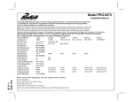
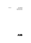
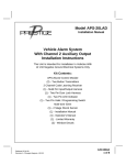
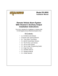
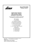
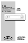
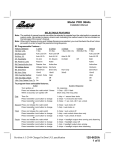
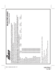
Model PRO 9842
Installation Manual
Vehicle Alarm System
With Channel 2 Auxiliary Output
Installation Instructions
This Unit Is Intended For Installation In Vehicles With
12 Volt Negative Ground Electrical Systems Only
Kit Contents:
PRO 9842 Control Module
(2) - Two Button Transmitters
2 Channel Code Learning Receiver
(1) - Multi Pin Input/Output Harness
(1) - Two Pin Door Lock Harness
(1) - Two Pin LED Indicator
(1) - Two Pin Valet / Programming Switch
Multi-tone Siren
(1) - Installation Manual
(1) - Operator's Manual
(1) - Limited Warranty
(2) - Window Decals
The PRO 9842 Vehicle Alarm System is designed to provide a basic deterrent to vehicle theft, and a
convenient electronic means to gain access to the vehicle by providing RF remote control over the vehicle's
power door lock system. The unit also includes outputs to control the vehicle's parking lights, and an
additional auxiliary output designed to allow for control over an optional device such as a power trunk
release or engine starting device.
BEFORE BEGINNING THE INSTALLATION:
1) Find locations to mount the following items:
Control Module
Electronic Siren
Dash Mounted L.E.D.
Valet/Program/Manual Override Switch
2) Determine the type of factory power door lock system in use. Knowing the type of system up front
before beginning the installation can make the installation easier and faster since you can build whatever
interface (if needed) beforehand.
3) Determine whether the vehicle includes a power trunk release system, and if so what type it is.
CONTROL MODULE:
The Control Module is NOT waterproof, DO NOT mount it in the Engine Compartment. Select a mounting
location under the dashboard. Choose a mounting location that will not interfere with proper operation of
the vehicle's steering column mechanism, brake and gas pedals. Secure the Control Module in the
chosen location. Wait until all components have been installed and all connections are made before
plugging in the main connectors.
SIREN:
Select a location in the engine compartment that is not accessible from below the vehicle. The selected
location must be clear of hot or moving parts within the engine compartment The siren must be pointed
downward to prevent water retention and the flared end must be pointed away from and out of the engine
compartment for maximum sound distribution. Before securing the siren, check behind your chosen
location to assure that the mounting screws will not penetrate any factory wiring or fluid lines. Secure the
siren mounting bracket using #8 self taping screws by first using the mounting bracket as a template,
scribe or mark the three bracket mounting holes. Drill the three marked holes using a 1/8" drill bit, than
mount the siren using #8 sheet metal screws.
VALET/PROGRAM/MANUAL OVERRIDE SWITCH :
Since much of the use of this switch by the vehicle operator requires concurrent operation of the ignition
key switch, it is recommended that the Valet/Program/Manual Override Switch be placed such that it can
be reached by the driver's left hand, while they operate the ignition key switch with their right hand. It is
also highly recommended that this switch be concealed to provide the highest level of security. The switch
can be mounted to the lower dash panel in the driver's area. Inspect behind the chosen location to insure
that adequate clearance is allowed for the body of the switch, and also that the drill will not penetrate any
existing factory wiring or fluid lines. Drill a 1/4" hole in the desired location and mount the switch by
passing it through the panel from the opposite side. Secure the switch using the nut, star-washer, and
on/off face plate. It is suggested that the switch be oriented to allow the on position to be up toward the
driver and the off position to be down or away from the driver. Route the switch’s wires and connector
toward the location of the Control Module.
DASH MOUNTED L.E.D.:
The small Red LED included in the kit serves as a visual indicator of the system's status and provides a
visual deterrent to a potential thief. The LED also provides important feed back information during the
transmitter and feature program modes. The LED should be installed in the dashboard in a highly visible
2
area that may be seen from the driver’s seat as well as from outside the vehicle. Try to choose a location
close enough to the Control Module so that the LED's wires will reach. Carefully inspect the area behind
your chosen location to insure that the drill will not penetrate any existing factory wiring or fluid lines. Drill
a 1/4" hole and pass the connector end of the LED through the hole, and route the wires toward the
location of the Control Module. Press the LED firmly into place until it is fully seated.
HOOD AND TRUNK PIN SWITCHES:
The pin switch included in this package is intended for protecting the hood or trunk/hatch areas of the
vehicle. In all cases, the switch must be mounted to a grounded metal surface. When the pin switch is
activated, (hood/trunk open), it will supply a ground to the input wire thus activating the alarm. Mount the
switches in the hood or trunk locations away from water drain paths. If necessary, the included bracket
may be used to move the switch away from rain gutters or allow mounting to the firewall behind the hood
seal. In both cases the switch must be set up to allow the hood or trunk door to depress the switch at least
1/4 inch when the hood or trunk is closed and fully extended when the hood or trunk is opened. For direct
mounting, a 1/4 inch hole must be drilled. Carefully check behind the chosen location to insure the drill will not
penetrate any existing factory wiring or fluid lines. Drill a 1/4" hole in the desired location and thread the
pin switch into it using a 7/16" nut driver or deep well socket. If using the mounting bracket, first secure
the bracket to the desired location and secure the pin switch in the pre-threaded mounting bracket hole.
WIRING CONNECTIONS:
RED Wire (Connects to RED/WHITE wire at harness plug): Main Power Input Wire
These are the main power input wires for the PRO 9842 system. Both wires connect to a separate
fuseholder contained in the harness. These fuseholders each hold a separate ATC fuse, one 5AMP and one
15AMP. This RED wire must be connected to a constant power wire at the vehicle's ignition switch harness
or fusebox. Most vehicles have at least one battery source wire supplying power to the ignition switch.
Locate a constant power wire or power taping point either at the vehicle's ignition switch harness or
fuseblock. This wire will read +12VDC at all times, regardless of the position of the ignition key switch.
Splice and tape the RED wire of the harness to this point.
YELLOW Wire: Ignition Input Wire
This wire provides the PRO 9842 system with an ignition power input from the vehicle. Connect this wire
to the primary ignition wire from the ignition switch. This vehicle wire will show +12VDC when the ignition
key is turned to the "ON" or "RUN" position and when turned to the "START" or CRANK" positions, and will
have 0VDC when the key is turned to the "OFF" and "ACCESSORY" positions.
Locate an ignition power wire at the vehicle's ignition switch harness. Splice and tape the YELLOW wire
of the system to this point.
WHITE Wire: Positive Parking Light Flash Wire
This wire is designed to provide a +12VDC positive light flash output, driven by the PRO 9842's internal
relay, to be connected directly to the vehicle's positive parking light circuit. Once the feedpoint is located,
confirm that all the vehicle's parking lights will illuminate when +12VDC is connected to it.
NOTE:Some vehicles, (mostly European) have isolated "left" and "right" side parking lights. To connect to
the parking light systems in these vehicles, you must use 2 separate SPDT or DPST relays to connect
one to each side in order to keep them isolated.
Locate a parking light feedpoint and attach the WHITE wire of the system to this point.
BROWN Wire: Negative (-) Door Trigger Input Wire
If the vehicle's interior lights are controlled by grounding door pin-switches (typical of most GM, Dodge,
and import vehicles), the Brown negative door trigger wire should connect to one of the vehicle's factory
door pin switches. In many cases the factory door pin-switches are wired in parallel, making it necessary
3
to connect to only one door switch in order to detect the opening of all doors. In a few cases this will not be
true, making it necessary to connect to the vehicle dome light, or isolate door trigger wires.
Locate the vehicle's negative door trigger wire in the vehicle's kick panel, under-dash or the vehicle's
pin-switch. Splice and tape the BROWN wire of the system to this point.
PURPLE Wire: Positive (+) Door Trigger Input Wire
If the vehicle's interior lights are controlled by +12VDC (Positive) door pin-switches (typical of most Ford
vehicles), the Purple positive door trigger wire should connect to one of the vehicle's factory door pin
switches. In many cases the factory door pin-switches are wired in parallel, making it necessary to
connect to only one door switch in order to detect the opening of all doors. In a few cases this will not be
true, making it necessary to connect to the vehicle dome light, or isolated door trigger wires.
Locate the vehicle's positive door trigger wire in the vehicle's kick panel or under-dash. Splice and tape the
PURPLE wire of the system to this point.
DARK GREEN Wire: Negative (-) Hood/Trunk Trigger Input Wire
This input is designed to connect to a grounding hood, trunk, or rear hatch pin-switch, to allow the system
to trigger should those entry points be violated. To provide protection for the hood, the Dark Green
negative hood/trunk trigger wire should connect to the existing factory hood pin-switch (if one exists) or to
a suitable aftermarket installed hood pin-switch. To provide protection for the trunk or hatch, the Dark
Green negative hood/trunk trigger wire should connect to the existing factory trunk or hatch pin-switch
wire that controls the trunk or hatch light circuit. In cases where both hood and trunk/hatch entry points
are to be connected together to the Dark Green wire, barrier diodes must be used to prevent the flow of
current from causing the under hood light to come on when the trunk/hatch is opened, and vice-versa. If
only the hood, or only the trunk/hatch is connected to the Dark Green wire, no diode is needed.
Note: The diodes which may be required for certain types of installations are the common 1N4000 series
type. You may chose to use any of the diodes in this series, with the 1N4003 and 1N4007 being the most
common types. The diodes must be installed with careful regard for their direction of current flow.
Note: This wire will be shunted when remote control channel 2 is accessed, (trunk release). This wire will
remain shunted all the while there is ground present and for 5 seconds after the ground is removed. This
allows the operator to open the trunk via the remote transmitter without having to first disarm the alarm system.
WHITE/BLACK Wire: Siren Output Wire
This wire provides a positive output (3A Max.) designed to directly drive a standard electronic siren. Find
a suitable mounting location for the siren and mount it properly. Run the Red wire of the siren into the
passenger compartment to the location of the PRO 9842. Connect the White/Black wire to the Red wire
from the siren. The Black wire from the siren should then be securely grounded to the vehicle chassis.
BLACK Wire: Main System Ground
This is one of the most important wires of the PRO 9842 installation. It must be connected properly to a
solid chassis ground it will help ensure reliable system operation. Special care must be taken to locate a
clean metal part of the chassis as an attachment point for this wire. Some installers prefer to locate a
sturdy metal bolt under the dashboard or at the kick panel, and use it as the attachment point.
If you find a suitable factory bolt that reads ground when tested, attach a insulated ring terminal connector to
the Black wire, remove the bolt, place the red ring terminal over the bolt and reinstall it, tightening it securely.
If you choose instead to drill your own mounting hole into the vehicle's chassis, be certain to remove any
paint or grease and secure the ring terminal using the self taping screw and star washer provided.
ORANGE Wire: Ground When Armed Output (Optional relay required.)
This wire provides a 300mA ground output when the alarm circuit is armed to control the starter inhibit
relay. Connect the Orange wire to terminal #86 of a standard SPDT relay. Connect terminal #85 of the
relay to an ignition wire in the vehicle that is +12VDC when the ignition key is turned to the on and start
positions and off when the key is in the off position. Locate and cut the low current starter solenoid wire
found at the vehicle's ignition switch harness. This wire will have +12VDC when the ignition key is moved
4
to the start (crank) position and will have 0 volts in all other key positions.
Connect one side of the cut wire to terminal #87a of the relay. Connect the other side of the cut wire to
terminal #30 of the relay.
DARK BLUE Wire: Delayed 300mA Pulsed, Channel 2 Output
The Dark Blue wire supplies a 300mA ground pulsed output whenever channel two of the receiver is
accessed. Pressing transmitter Button 2 for three seconds will access Channel 2. This is a low current
output and must be connected to a relay to supply power to the trunk release or the circuit you wish to
control. Connect the Dark Blue wire to terminal # 86 of a VF45F11 P&B relay or equivalent. Connect
terminal # 85 of the relay to a fused +12VDC source. Connect the common, normally open, and normally
closed contacts of the relay to perform the selected function of Channel 2.
DOOR LOCK/UNLOCK CONTROL HARNESS (+) and (-)
2-PIN White Plug w/2 Wires; RED & GREEN
The Red and Green Door Lock/Unlock output wires provide either a momentary pulsed ground (-) or a
momentary pulsed 12VDC (+) output for controlling a vehicle's power door lock/unlock circuit. In order to
accomplish this "dual polarity" output scheme these two wires produce the opposite polarity at the opposite
time. To better understand this, refer to the table below:
ÿþýü úùøùý
þù
ùøýþ
ÿþý
ý
ÿþý
þ
þþ
þ
þþ
ý
The output of these wires has a maximum switching capability of 300mA. Many vehicles today have
factory door lock relays which can be connected directly to these outputs, however always confirm that the
factory relays in your particular vehicle do not exceed the rated 300mA output of the units door lock/unlock
circuit. Plug the two pin connector of the door lock/unlock harness into the mating connector shell of the
control module. Determine the door lock circuit of the vehicle you are working on and wire according to
the diagrams shown.
WIRING FOR "GROUND PULSE" DOOR LOCK CIRCUITS:
This is a system commonly used on most import vehicle's factory door lock/unlock systems, and with a few
domestic vehicles which employ factory "keyless entry" systems. In this application, the Red wire serves
as the "Lock" output, providing a ground pulse during the arming sequence, and the Green wire serves as
the "Unlock" output, providing a ground pulse during the disarming sequence.
Connect the Red wire to the low current ground factory door "Lock" signal wire leading from the factory
switch to the factory door lock relay. Connect the Green wire to the low current ground factory door
"Unlock" signal wire leading from the factory switch to the factory door unlock relay.
WIRING FOR "POSITIVE PULSE" DOOR LOCK CIRCUITS:
This is a system commonly used on many domestic vehicle's factory door lock/unlock systems, particularly General Motors and Chrysler, although not on all models. (Please see the note regarding "5-Wire
Reverse Polarity Door Lock Systems"). In this application, the Green wire serves as the "Lock" output,
providing a positive pulse during the arming sequence, and the Red wire serves as the "Unlock" output,
providing a positive pulse during the disarming sequence.
Connect the Green wire to the low current positive (+12VDC) factory door "Lock" signal wire leading from
the factory switch to the factory door lock relay. Connect the Red wire to the low current positive (+12VDC)
factory door "Unlock" signal wire leading from the factory switch to the factory door unlock relay.
4 WIRE POLARITY REVERSAL and 5 WIRE ALTERNATING DOOR LOCK CONTROL CIRCUITS:
In these applications, the AS-9159 Door Lock Interface (or equivalent 30 Amp. automotive type relays) must be
used. Refer to the Audiovox Door Lock Wiring Supplement for proper connection to these types of circuits.
5
PLUG-IN CONNECTIONS AND COMPLETING THE INSTALLATION:
Now that all the other components have been installed, and most of the main connections completed, it is
time to finish connecting the remaining plug-in components and completing the installation. Even though
these are plug-in connections, and the plugs have been shaped such that they cannot be plugged in wrong,
please read and follow the instructions below for each connection to make certain each component is
properly installed.
DASH MOUNTED LED
2-PIN White Plug w/2 Wires; Red & Blue
The Red & Blue wires in the 2-PIN mini white connector control the anode and cathode of the dash
mounted LED. Route the twin lead Red and Blue wires from the LED to the control unit and plug the two pin
connector into the mating white mini connector shell of the control module. Do not force the connector, it
will only plug in one way.
OPTIONAL SHOCK SENSOR
4-PIN White Plug w/4 Wires; Red, Black, Blue, & Green
The Red (+12 volt), Black (ground), Blue (pre-detect) and Green (full trigger when armed) wires loaded
into the white connector shell are the inputs/outputs of the shock sensor. Route the 4 wire harness from
the shock sensor location to the PRO 9842 Control Module and plug the 4-PIN white connector into the
mating 4-PIN connector.
VALET/PROGRAM/MANUAL OVERRIDE SWITCH
2-PIN Blue Plug w/2 Wires; Black & Gray
The Black & Gray wires in the 2-PIN blue connector are the ground supply and Valet/Program input of the
PRO 9842 unit. When the Gray wire is grounded, under certain conditions, the unit will enter the valet
mode. When the Gray wire is sequentially grounded under other conditions, the unit will enter the various
program modes. Route the Black and Grey wires from the Valet/Program/Manual Override switch to the
PRO 9842 unit and plug the blue 2-PIN connector into the mating blue connector shell of the PRO 9842
control module. Do not force the connector, it will only plug in one way. Note: Please refer to the section;
"Programming System Features" shown later in this installation guide to learn the operation of the valet/
program/manual override switch.
POWER DOOR LOCK HARNESS
2-PIN White Plug w/2 Wires; Red & Green
The connection of the power door lock/unlock wires has already been explained. Route the Red and Green
wires to the PRO 9842 unit and plug the white 2-PIN connector into the mating white two pin connector
shell of the PRO 9842 control module. Do not force the connector, it will only plug in one way.
TRANSMITTER PROGRAMMING:
The transmitters supplied with the PRO 9842 are pre-programmed at the factory to provide the following function:
Button 1, pressed and released quickly
=
Arm/Disarm (Lock & Unlock) w/Siren Chirps
Button 1, pressed for ~ 1 second
=
Arm/Disarm (Lock & Unlock) w/o Siren Chirps
Button 1, pressed for ~ 3 seconds
=
Engage/Disengage Panic Mode
Button 2, pressed for ~ 3 seconds
=
Channel 2 Output
If you desire to have the transmitters operate differently from this factory configuration, please refer to the
separate Transmitter Programming Guide that came with the PRO 9842 system.
PROGRAMMING FEATURES:
There are five (5) Programmable Features on the PRO 9842 system. Study the list below, keeping in mind
the features and their defaults, (how it comes programmed from the factory), and decide how best to
program the PRO 9842 for your particular installation.
6
Programmable Features:
Features
1 Chirp
2 Chirp
Default
First
Passive Arming
Active Arming
Passive Arming
Second
Ignition D/L ON
Ignition D/L OFF
Ignition D/L OFF
Third
Ignition D/UL ON
Ignition D/UL OFF
Ignition D/UL OFF
Fourth
Passive D/L
Active D/L
Active D/L
Fifth
Chirps ON
Chirps OFF
Chirps ON
To Program These Features:
Entering the Programming Mode involves operating the Ignition Switch and the Valet/Program/Manual Override
Switch in a particular sequence. This sequence is very time dependent, in other words it must be performed
quickly in order for you to enter the mode. This sequence is also only one step different from the Transmitter
Programming Mode, so make certain you perform the sequence properly.
Upon entering the Programming Mode, the system is immediately set to allow adjustment of the First
Programmable Feature. That First feature, "Passive or Active Arming", can then be set ON or OFF by
pressing button 1 of the transmitter. The system confirms that it is set to adjust the First feature by
repeatedly flashing the LED once, with a pause in between each flash. The system will then report how the
feature has been set by the number of chirps heard after pressing the transmitter button. Toggling the Valet/
Program/Manual Override Switch once again will advance you to the Second Programmable Feature,
confirmed by a repeating two LED flashes, with a pause in between each flash, etc., etc.
It is important to note that when you first enter the Programming Mode, you are automatically positioned to
adjust the First Programmable Feature, and that the Valet/Program/Manual Override Switch allows you to
toggle from there through each of the four more programmable features. However, it will not allow you to
return to any feature once you have toggled past it. Should you accidentally toggle past the feature you
wanted to program, you must exit and re-enter the Programming Mode and then adjust the feature you missed.
It is also important to note that you may toggle past as many programmable features as you wish without
having to adjust them. Each time you toggle forward to a new feature, the siren will chirp the appropriate
number of times (1 or 2 times) to indicate how that feature is currently set, and the LED will flash the
appropriate number of times to indicate the number of the feature (First through Fifth) that you are set to
adjust. For example, you might enter the mode and toggle the Valet/Program/Manual Override Switch 3
times in order to adjust the Fourth programmable feature. The system would respond with 1 Chirp, and the
LED would begin to flash 4 Flashes, pause, and repeat. This has told you that the system is ready for you
to adjust the Fourth programmable feature, and that it is currently programmed for Chirps ON. A single
press of button 1 of the transmitter will cause the system to produce 2 Chirps. This signifies that you have
changed the programming to Chirps OFF. Please follow the programming procedure carefully, and refer to
the list of the Programmable Features above when programming the PRO 9842.
7
ÿþýüûúþ
ý ü
þÿ
þ
ü
þúÿ ú
úþ
þ ÿú
üþ
ÿ
þÿ
ÿ
ÿ
ÿ
ÿ
ÿ
þ
ÿÿ
ÿ
ÿ
ÿ
ÿÿ
þ
ÿ
þ
ýüüþú
þ
ÿ
þ
ÿ
þ
þ ÿ ý
ÿ
ÿ
ÿ
ÿ
ÿþ þÿ
þ
ÿ
ÿ
ÿ
ÿþ þÿ
þ
ÿ
ÿ
ÿþ þÿ
þ
ÿ
ÿ
ÿ
ÿþ þÿ
þ
ÿ
ÿ
ÿ
ÿ
ÿ
ÿ
ÿ
ÿ
ÿ
ÿ
ÿ
ÿ
ÿ
ÿÿ ÿ
ÿÿ ÿ
ÿ
ÿ
ÿ
ÿ
ÿ
ÿ
ÿ
ÿ
ÿ
ÿ
ÿþ þ
ÿ
ÿ
ÿ
ÿ
ÿ
ÿÿ
ÿ ÿ
ÿ
ÿ
ÿ
COMPLETING THE INSTALLATION:
After you have confirmed the operation of the PRO 9842, and tested any and all optional features of the
system:
1. Mount the control module up and behind the dash securing it in place with cable ties or screws. Be
certain that the chosen mounting location will not inhibit any of the controls of the vehicle.
2. Securely harness and tie all wiring up and away from all hot and moving parts that they may come in
contact with under the dash board or in the engine compartment areas.
CAUTION: Particularly avoid the area around the steering shaft and column, as wires can wrap around
these mechanisms and impair the safe operation of the vehicle.
3. Check the vehicle's wipers, lights, horn, etc... to insure proper operation.
4. Replace all panels that were removed during installation, and retest the system.
5. Explain the operation of the system and its various features to the end user if available, and place the
Owner's Manual on the dashboard for them to find and review.
8
To (Optional)
Plug-In Shock Sensor
PRO 9842
© 1999 Audiovox Corp.
9
128-5451