1
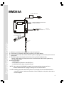
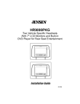
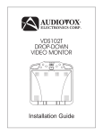
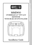
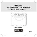
8.5" OVERHEAD LCD VIDEO MONITOR WITH DVD PLAYER ON OF F A U TO 5 P OW ER S O U R CE S C RE EN STOP E JEC T P L AY Installation Guide 1 Installation Guide MMD85A Important Notice Installation Guide An LCD panel and/or video monitor may be installed in a motor vehicle and visible to the driver if the LCD panel or video monitor is used for vehicle information, system control, rear or side observation or navigation. If the LCD panel or video monitor is used for television reception, video or DVD play, the LCD panel or video monitor must be installed so that these features will only function when the vehicle is in “park” or when the vehicle’s parking brake is applied. An LCD panel or video monitor used for television reception, video or DVD play that operates when the vehicle is in gear or when the parking brake is not applied must be installed to the rear of the driver’s seat where it will not be visible, directly or indirectly, to the operator of the motor vehicle. Licensed under one or more of the following patents, Patent NOS. 5,775,762 and 5,927,784 2 1) 2) 3) 4) 5) 6) MMD85A Video Monitor with DVD player (P/N 136-4052) (1 pc) A/V Adapter Cable (P/N112B3227) (1 pc) 2 Pin Power Wire Harness with choke (P/N112B3143) (1 pc) Dome Light Harness (P/N 112B3110) (1pc) Remote Control (P/N 136-4057) (1pc) Hardware Package:• # 8 × 3/4" Self Drilling Screws (4 pcs) • # 8 Washers (4 pcs) • # 4 × 1/4" Screws (9 pcs) 7) Trim Ring (P/N 102-4143) (1pc) 8) Universal Mounting Bracket (P/N 108-3867) (1pc) 1. ON 5. 2. OF F AUT O 5 P OWE R S OU RC E S C RE E N S TOP E JE CT P LA Y 3. 4. 6. 7. 8. TOOLS REQUIRED: #2 Phillips Screwdriver #1 Phillips Screwdriver Utility or Razor Knife or Shears Wire Strippers Upholstery hook tool (for removal of panels as necessary) Electrical Tape Masking Tape Multimeter (to verify 12 volt DC and continuity: Do not use a test light or logic probe) Marker pen – to mark headliner Scribe (to mark trim ring if used) Misc. electrical connectors (to connect to vehicle power source). Requirements will vary from vehicle to vehicle. 3 Installation Guide MATERIALS INCLUDED IN THIS PACKAGE: GENERAL INSTALLATION APPROACH: 1) Decide upon system configuration and options that will be installed (i.e.: what components, VCP, Tuner, RF Modulator/external amp, remote headphones, DVD, etc.). 2) Review all manuals to become familiar with electrical requirements and hook ups. 3) Decide upon mounting locations of all components and method of mounting. 4) Prep the vehicle by removing any interior trim necessary to gain access to vehicle's wiring as well as all areas where interconnecting wire harnesses will need to be located. If any access holes need to be cut into the vehicle (headliner, other trim components etc.), this should be done now as well. 5) Route the wiring harnesses throughout the vehicle as necessary. (Refer to the Wiring Diagrams in this manual as well as the wiring instructions for the individual components and accessory options being installed). Be sure that all wiring is protected from sharp edges and is routed in such a manner that it will not be pinched when all components and interior trim are fully installed. Be sure to leave enough slack in the wiring at each component to allow working room. 6) Remove all A/V system components from their packaging and place them loosely in the vehicle at their respective locations. 7) Connect all components together (electrically) and verify proper operation of all system functions. Note: This is best done BEFORE components have been permanently mounted. 8) After verifying proper operation of the system, proceed to mount each of the components. Installation Guide 9) When all components are mounted, recheck function of entire system again to ensure that no wiring was pinched or connected improperly during final installation. 4 1) Locate an accessory power source (+12v when key is in the ACC. and run positions, and 0v when key is off). Also find a location that will provide a good grounding point. Generally, this wire can be found at the ignition switch or fuse-box. 2) The mounting method and location will vary from vehicle to vehicle, so this manual will only focus on the installation of the video monitor and related accessories. 3) Generally, the best location for the video monitor is where the vehicle's factory dome light is installed. The monitor should be located in such a manner that it can be comfortably viewed by rear seat passengers. NEVER INSTALL THE MONITOR IN A PLACE WITHIN THE DRIVER'S VIEW. THIS IS NOT ONLY DANGEROUS, BUT IT IS ALSO ILLEGAL. 4) Once the mounting location of the monitor has been determined, there may be additional preparation work necessary, depending on the vehicle structure and installation method. Some of the steps that may be required are: A) B) 5 Removal of the vehicle's dome light The headliner may need to be trimmed Installation Guide VEHICLE PREPARATION: TRIM RING INSTALLATION: If the video monitor is to be installed with the trim ring, you may want to remove the rubber gasket first. (See the drawing below). R ubber G asket 1) Lay the MMD85A down on a soft surface to avoid scratching the unit. Grasp the rubber gasket above the DVD slot and pull it off in a circular motion. (Refer figure 1) Installation Guide Figure 1 Trim R ing 2) The trim ring is attached to the video monitor using the perimeter screw bosses. It is important that the screws used in this installation are not overtightened, and that the video monitor and trim ring are mounted in such a way that the assembly does not distort (or bend) when the mounting screws are tightened. The trim ring MUST be screwed to the unit. (Refer figure 2) Figure 2 3) The MMD85A is now ready to be mounted in the vehicle. (Refer figure 3) Figure 3 6 Roof Roof Support Headliner Mounting Bracket (4) Self-Tapping Screws (not supplied) Trim Ring Video Unit (5) #8 Flat Washers (5) #8x3/4 Self-Tapping Screws 7 Installation Guide MOUNTING THE TRIM RING MMD85A * O P TIONAL RELAY BOX S IR S W B * ANTENNA FOR WIRELESS FM MODULATOR ** See Antenna Note Below Red/Black (Lamp On) Violet/Brown (Lamp Auto) Black/Red (Lamp Common) D om e Lig h t P ow e r S ou rc e Lin e In -V (Ye llow ) Lin e In -R (R e d) Lin e In -L (W hite ) C H O KE Installation Guide Po w e r H arn es s Ite m # 3 1) Make the connections to the vehicle for the 2 pin wiring harness. 2) Connect the 2 pin harness to the mating connector on the Video Monitor. 3) Connect power harness to vehicle's electrical system by tapping into an accessory hot line and a good ground. 4) Verify all functions of the System before final mounting of the finished assembly. Note: A VCP or other A/V Component can be connected to the video monitor system using the LINE IN RCA jacks. A/V Source Definitions : 1 = Built-in DVD 2 = AV1 input ( VCD, Game or future DVD, etc ) 3 = AUX input ( VCD, Game or future DVD, etc ) * NOTE: If the relay box P/N SIRSWB is installed, it recommended that the antenna for the wireless FM Modulator be unplugged. See Figure A for antenna location. ** NOTE: Extending the wireless antenna beyond its 12 inch length will cause the FM Modulator to exceed FCC limits for wireless transmission. When installing the unit position the antenna for best reception. 8 The dome lights in the video monitor require three connections to the vehicle's wiring. There are two common types of dome light circuits used, positive or negative switched. Positive systems supply voltage to the interior lights to turn them on, negative switched systems apply ground to illuminate the bulbs. To determine which system you have you must locate the wires at the dome light. On a positive switched system, with all the doors closed and the lights out, both wires at the dome light will rest at ground. When the light is activated, one of these wires will switch to +12 vdc. This is the vehicle's switching wire. On a negative switched system, with all the doors closed and the lights out, both wires at the dome light will rest at + 12vdc. When the light is activated, one of these wires will switch to ground. This is the switching wire. For positive systems, connect the violet / brown (Lamp auto) wire to the vehicle's switched wire. Then connect the red / black (lamp on) wire to a fused constant 12 volt source and the black / red (lamp common) wire to a good ground. Positive systems are commonly found on Ford vehicles. For negative systems, connect the violet / brown (Lamp auto) wire to the vehicle's switched wire. Then connect the red / black (lamp on) wire to a good ground and the black / red (lamp common) wire to fused constant 12 volt source. Negative systems are commonly found on General Motors and import vehicles. Note: Some vehicles which incorporate transistorized control of the dome light circuit, such as the 1999 Dodge Caravan, may require that the violet / brown (Lamp auto) wire be connected to the door pin switch wire, as the additional current draw of the Monitor's lights may not be supported by the output of the vehicles body control computer. Positive Switched Dome lighting To 3 pin connector on Monitor Red / black - Lamp on Black / red - Lamp common Violet / brown - Lamp Auto Factory Dome light circuit To constant +12vdc Factory Door ajar switch or Body Control computer 9 To constant +12vdc Installation Guide CONNECTING THE DOME LIGHTS Negative Switched Dome lighting To 3 pin connector Red / black - Lamp on Black / red - Lamp common Violet / brown - Lamp Auto To constant Factory Dome light circuit To constant Factory Door ajar switch or Body Troubleshooting: SYMPTOM: REMEDY: No power at Video Monitor -Verify +12 VDC on Red wire at 2 pin Power Harness behind video monitor. Verify ground connection with continuity test from known good ground to black wire at 2 pin Power Harness Power but no video or sound -Verify that the correct source is selected (i.e.: 1 or 2). Verify that the source is on and playing a known good media (such as a videotape). Verify connections at both ends of the source component harness. Picture, but no sound -Verify that the headphones are turned on; check headphone batteries -Verify that power is available to the FM Modulator; make sure modulator is tuned to the correct FM station © Copyright 2005 AEC 150 Marcus Blvd. Hauppauge, NY 11788 128-7461