1
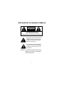
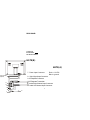
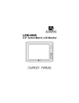
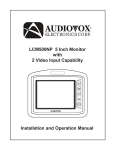
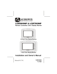
LCM-5600NP
5.6" Active Matrix LCD Monitor
Owner’s Manual
EXPLANATION OF GRAPHIC SYMBOLS
CAUTION
RISK OF ELECTRIC SHOCK
DO NOT OPEN
CAUTION : TO REDUCE THE RISK OF ELECTRIC SHOCK
DO NOT REMOVE COVER (OR BACK)
NO USER-SERVICEABLE PARTS INSIDE
REFER SERVICING TO QUALIFIED SERVICE PERSONNEL
The lightning flash with the arrowhead within
a triangle is intended to alert tell the user
that parts inside the product are capable of
producing an electric shock .
The exclamation point within a triangle
is intended to alert the user that important
operating and servicing instructions are
being provided.
WARNING: TO PREVENT FIRE OR ELECTRIC SHOCK
HAZARD, DO NOT EXPOSE THIS PRODUCT
TO RAIN OR MOISTURE.
2
SPECIFICATIONS
1. Type:
Color Liquid Crystal Display (LCD)
Monitor
2. Display Screen Size:
5.6 inches
(114.2 x 83mm) ( W x H )
Element : TFT LCD
Format : 480 (W) x 234 (H) dot
Total 112,320 dot
3. Back Light:
Cold Cathode Fluorescent Lamp
4. Power Source:
+12 VDC
5. Power Consumption:
11W
6. Connection Terminals:
Video/Audio Input Jacks (RCA)
External Power Jack (DC IN 12V)
IR Jack
7. Operating Temperature: 32°F - 104°F
(0°C - 40°C)
8. Storage Temperature:
-4°F - 176°F
(-20°C - +80°C)
9. Cabinet Dimensions:
6.29 in x 4.52 in X 1.14 in (WxHxD)
(160 x 115 x 29 mm)
10. Weight:
1.33 lbs (500g)
11. Video Format:
PAL, NTSC
3
CONTROLS AND INDICATORS
FRONT PANEL
1
2
3
4
5
6
1. Power On LED Indicator
2. Power On/Off Switch
3. Remote Control Sensor
4. Picture Select
5. On Screen Adjustment Up Button
6. On Screen Adjustment Down Button
4
REAR PANEL
To Optional
IR Transmitter
Part Number IRT456
NOTE(B)
NOTE(A)
7. Power Input Connector:
To IR Tansmitter
(Optional)
8. Video Signal Input Connector
9. IR Repeater Connector
10. IR Repeater Transmitter
11. Audio Right Channel Input Connector
12. Audio Left Channel Input Connector
11
12
8
7
5
10
9
Red = +12 VDC
Black = ground
Note A : This cable (10) is utilized to connect to Video Cas-
sette Players that do not accept the IR Repeater 1/8"
(3.5mm) style plug (9). The IR Repeater Transmitter is
provided with an adhesive that allows it to adhere to
Video Cassette Player remote sensor. Remove the
backing covering the adhesive and place the IR Repeater Transmitter directly over the Video Cassette
Player remote sensor.
Note B : Connector (11) and (12) are Audio input Jacks reserved
for optional IR Wireless Transmitter use (IRT456).
IR Wireless Transmitter is a device for transmitting
(audio sound without using wires) to IR Headphones.
Please contact Audiovox dealers for this optional accessory.
OPERATION
1. Connect the monitor power input plug (7) to a DC power
source (Red plug +12 VDC, Black plug (-) to ground).
2. Connect the external video source output signal (from VCP/
DVD, TV Etc.) to the VIDEO IN jack (8).
3. Press power On/Off button (2) to turn the monitor on and off.
The LED power indicator will light red.
4. Press the Picture Select button (4) to adjust the picture display characteristics. The adjustments will be shown on the
On Screen Display in the following sequence: Contrast,
Brightness, Color, and TINT.
5. While in the picture select mode (video adjustment), press
the up button (5) to increase the selected adjustment level
or press the down button (6) to decrease the level.
6
GENERAL INSTALLATION INFORMATION
1. Installation will vary from vehicle to vehicle, as headrests in
vehicles are not standard.
2. This unit is intended for installation by professional installers.
3. The kit consists of the screen assembly, a mounting housing, key to remove screen from housing, wiring harness,
remote control unit and remote control unit batteries.
4. To release screen from housing, slide the key on either the
right or left side of the screen between the housing and screen
assembly to release the two clips which hold the screen
assembly in the housing.
5. To install the screen assembly into the housing simply insert
the screen assembly until you hear the clips click into the
locking position.
6. Headrests will have to be cut to install the screen assembly
housing.
Caution - Do not over-cut the headrest beyond the height and
width of the housing.
7. To fasten the housing to the headrest, use either screws or
tie wraps. Find a suitable mounting surface in the headrest
to secure the housing.
Caution - Use the proper length screws, which will vary with
each headrest. If a suitable mounting surface cannot be found,
use tie wraps to secure the housing.
8. Attach the wiring to the screen, through the housing into and
down the headrest and seat before permanently mounting
the housing and screen assembly.
9. Follow the wiring diagram in the owner’s manual for proper
wiring connections.
7
NOTE: A Remote Control Unit is included which will perform
the Functions and adjustments of Operation items 3,
4, and 5 as well as additional features as noted below.
REMOTE CONTROL FUNCTIONS:
LCD/VCP: ........ Power button for LCD/VCP
REPLAY: .......... Press to rewind tape and automatically go to
play mode.
PICTURE SEL: .On Screen Display (OSD) for color, tint, brightness,
contrast. Use ± to adjust
REW: ............... Rewinds tape
FWD: ............... Fast Forward tape
PLAY: ............... Plays tape
STOP: ..............Stops tape
CAUTION
1. Do not operate the monitor at temperatures below 32°F
(0°C) or above 104°F (40°C).
2. Keep the monitor clean and dry.
3. Always seek qualified personnel to perform repairs. Never
attempt your own repairs.
4. Do not drop the monitor or expose to strong impacts.
5. Do not expose to direct sunlight for extended periods of
time.
© 2001 Audiovox Electronics Corp., Hauppauge, NY
8
128-5973A