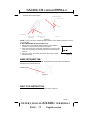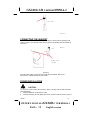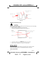
1
GX2401c U.S. I/B version 09050A-1 GX2401c Congratulations on your selection of the GX2401c from AUdiovox®. This quality 2.4GHz cordless telephone with Caller ID and Call Waiting, like all Audiovox® products, has been designed to give you many years of continuous service OWNER’S MANUAL#GX2401cVER.09050A-1 PAGE: 0 English version GX2401c I/B version 09050A-1 and represents the best value for your money. It requires little maintenance and is easy to setup and operate. IMPORTANT SERVICE INFORMATION Read this manual before attempting to setup or use this instrument. It contains important information regarding safe installation and use. Keep this manual for future reference. Also save the carton, packing and proof of purchase to simplify and accelerate any needed action. If you need assistance or service, call (800) 229-1235 between 9:00a.m. & 5:00p.m. Eastern Standard Time, Mon. – Fri. You can also visit our web site at: http://www.audiovox.com for technical support and information on our other products. WARNING To prevent fire or shock hazard, do not expose this product to rain or any type of excess moisture. If accidentally dropped into water, the adapter should immediately be unplugged from the wall along with the telephone line cord. THIS SYMBOL IS INTENDED TO ALERT THE USER OF THE PRESENCE OF IMPORTANT OPERATING AND MAINTENANCE (SERVICING) INSTRUCTIONS IN THE OWNER'S MANUAL. CARTON CONTENTS HANDSET ADAPTER (DC9V, 300mA) BASE UNIT RECHARGEABLE Ni-Cd BATTERY PACK TELEPHONE LINE WALL MOUNT CORD BRACKET 1 BELT CLIP 09050A-1 OWNER’S MANUAL#GX2401c VER.09050A-1 PAGE: 1 English version GX2401c I/B version 09050A-1 (Short & Long) USER’S MANUAL ACCESSORY ORDER FORM SAVE THESE INSTRUCTIONS IMPORTANT SAFETY INSTRUCTIONS When using your telephone equipment, basic safety precautions should always be followed to reduce the risk of fire, electric shock, and injury to persons, including the following: 1. Read and understand all instructions. 2. Follow all warnings and instructions marked on the product. 3. Unplug this product from the wall outlet before cleaning. Do not use liquid cleaners or aerosol cleaners. Use a damp cloth for cleaning. 4. Do not use this product near water, for example, near a bathtub, washbowl, kitchen sink, laundry tub, in a wet basement or near a swimming pool. 5. Do not place this product on an unstable cart, stand, or table. The product may fall, causing serious damage to the product. 6. Slots and openings in the cabinet at the back or bottom are provided for ventilation, to protect it from overheating. These openings should never be blocked or covered. The openings should never be blocked by placing the product on the bed, sofa, rug, or other similar surface. This product should never be placed near or over a radiator or heat register. This product should not be placed in a built-in installation unless proper ventilation is provided. 7. This product should be operated only from the type of power source indicated on the marking label. If you are not sure of the type of power supply to your home, consult your dealer or local power company. 8. Do not allow anything to rest on the power cord. Do not locate this product where the cord will be abused by persons walking on it. 9. Do not overload wall outlets and extension cords as this can result in the risk of fire or electric shock. 10. Never push objects of any kind into this product through cabinet slots as they may touch dangerous voltage points or short out parts that could result in a risk of fire or electric shock. Never spill liquid of any kind on the product. 11. To reduce the risk of electric shock, do not disassemble this product, but take it to a qualified service contractor when some service or repair work is required. Opening or removing covers may expose you to dangerous voltages or other risks. Incorrect reassembly can cause electric shock when the appliance is subsequently used. 12. Unplug this product from the wall outlet and refer servicing to qualified service personnel under the following conditions: A. When the power supply cord or plug is damaged or frayed. B. If liquid has been spilled into the product. C. If the product has been exposed to rain or water. D. If the product does not operate normally by following the operating instructions. Adjust only those controls that are covered by the operating instructions. Improper adjustments of other controls may result in damage and will often require extensive work by a qualified technician to restore the product to normal operation. E. If the product has been dropped or the cabinet has been damaged. 09050A-1 2 OWNER’S MANUAL#GX2401c VER.09050A-1 PAGE: 2 English version GX2401c I/B version 09050A-1 F. 13. 14. If the product exhibits a distinctive change in performance. Avoid using a telephone (other than a cordless type) during an electrical storm. There may be a remote risk of electric shock from lightning. Do not use the telephone to report a gas leak in the vicinity of the leak. The RBRC Seal The RBRC Seal on the (easily removable) Nickel-Cadmium battery (contained in your product) indicates that Audiovox Communications Corp. (Audiovox) is voluntarily participating in an industry program to collect and recycle these batteries at the end of their useful lives. When taken out of service within the United States, the RBRC program provides a convenient alternative to placing used Nickel-Cadmium batteries into the trash or municipal waste, which is illegal in some areas. Audivox’s participation in RBRC makes it easy for you to drop off the spent battery at local retailers of replacement Nickel-Cadmium batteries, or at authorized AUDIOVOX’s product service centers. You may also contact your local recycling center for information on where to return the spent battery. Please call 1-800-8BATTERY for information on Ni-Cd battery recycling in your area. AUDIOVOX’s involvement in this program is part of its commitment in protecting our environment and conserving natural resources. Detach the battery compartment cover on the handset. Then, remove the Nickel-Cadmium battery pack. RBRC is a trademark of Rechargeable Battery Recycling Corporation. SAVE THESE INSTRUCTIONS BATTERY SAFETY INSTRUCTION CAUTION: To reduce the risk of fire or injury to persons, read and follow these instructions: 1. Use only the following type and size of handset battery pack: Cordless Telephone Battery Pack DC3.6V, 850mAh, Ni-Cd Battery Pack Model No.: BT2400 2. Do not dispose of the battery in a fire. The cell may explode. Check with local codes for possible special disposal instructions. 3. Do not open or mutilate the battery. Released electrolyte is corrosive and may cause damage to the eyes or skin. It may be toxic if swallowed. 4. Exercise care in handling the battery in order not to short the battery with conducting material such as rings, bracelets and keys. The battery or conductor may overheat and cause burns. 5. Recharge only the battery provided with or identified for use with this product. The battery may leak corrosive electrolyte or explode if it is not the correct type. 6. Do not attempt to rejuvenate the battery provided with or identified for use with this product by heating them. Sudden release of the battery electrolyte may occur causing burns or irritation to eyes or skin. 7. When inserting the batteries into this product, the proper polarity or direction must be observed. Reverse insertion of batteries can cause charging that may result in leakage or explosion. 8. Remove the batteries from this product if the product will not be used for a long period of time (several months or more) since during this time the battery could leak in the product. 9. Do not store this product, or the battery provided with or identified for use with this product, in high-temperature areas. Batteries that are stored in a freezer or refrigerator for the purpose of extending shelf life should be stabilized at room temperature prior to use after cold storage. 3 09050A-1 OWNER’S MANUAL#GX2401c VER.09050A-1 PAGE: 3 English version GX2401c I/B version 09050A-1 10. Disconnect telephone lines before installing batteries. FCC / IC NOTICE This equipment complies with Parts 15 and 68 of the Federal Communications Commission (FCC) rules for the United States. It also complies with regulations RSS210 and CS-03 of Industry and Science Canada. Operation is subject to the following two conditions: (1) this device may not cause interference, and (2) this device must accept any interference that may cause undesired operation of the device. A label is located on the underside of the Base Unit containing either the FCC registration number and Ringer Equivalence Number (REN) or the IC registration number and Load Number. You must, upon request, provide this information to your local telephone company. This equipment is compatible with inductively coupled hearing aids. Should you experience trouble with this telephone equipment, please contact: AUDIOVOX COMMUNICATIONS CORP. SERVICE DEPARTMENT at (800) 229-1235. The telephone company may ask you to disconnect this equipment from the line network until the problem has been corrected. FCC Part 15 WARNING: Changes or modifications to this unit not expressly approved by the party responsible for compliances could void the user’s authority to operate the equipment. The equipment has been tested and found to comply with part 15 of the FCC rules. These limits are designed to provide reasonable protection against harmful interference in a residential installation. This equipment generates, uses and can radiate radio frequency energy and, if not installed and used in accordance with the instructions, may cause harmful interference to radio communications. However, there is no guarantee that interference will not occur in a particular installation. If this equipment does cause harmful interference to radio or television reception, which can be determined by turning the equipment on and off, the user is encouraged to try and correct the interference by one or more of the following measures: Reorient or relocate the receiving antenna. Increase the separation between the equipment and receiver. Connect the equipment to an outlet or on a circuit different from that to which the receiver is connected. Consult the dealer or an experienced radio/TV technician for help. FCC Part 68 The FCC requires that you connect your cordless telephone to the nationwide telephone network through a modular telephone jack (USOC RJ11C, RJ11W, or RJ14). Your telephone company may discontinue your service if your equipment causes harm to the telephone network. They will notify you in advance of disconnection, if possible. During notification, you will be informed of your right to file a complaint with the FCC. Occasionally, your telephone company may make changes in its facilities, equipment, operation, or procedures that could affect the operation of your equipment. If so, you will be given advanced notice of the change to give you an opportunity to maintain uninterrupted service. The Base Unit contains no user serviceable parts. The Handset contains a user replaceable battery. If it is determined that your telephone equipment is malfunctioning, the FCC requires that it not be used and that it be unplugged from the modular jack until the problem has been corrected. Repairs to this telephone equipment can only be made by the manufacturer or its authorized agents or by others who may be authorized by the FCC. For repair procedures, follow the instructions outlined under the AUDIOVOX Limited Warranty. 09050A-1 4 OWNER’S MANUAL#GX2401c VER.09050A-1 PAGE: 4 English version GX2401c I/B version 09050A-1 This equipment may not be used on coin service provided by the Phone Company or Party Lines. The REN is useful in determining the number of devices you may connect to your telephone line and still enable the devices to ring when you receive a call. The general rule is that the REN value should not exceed 5.0A total: however, contact your local telephone company for the specific number in your area. IC (Industry Canada) This telephone is registered for use in Canada. NOTICE: The REN assigned to this device denotes the number of devices you may connect to the telephone loop which is used by the device to prevent overloading. The termination on a loop may consist of any combination of devices subjected only to the requirement that the sum of the REN does not exceed five (5.0). NOTICE: The Industry Canada label identifies certified equipment. This certification means that the equipment meets certain telecommunications network protective, operational and safety requirements. The Department does not guarantee the equipment will operate to the user’s satisfaction. Before installing this equipment, users should ensure that it is permissible to be connected to the facilities of the local telecommunications company. The equipment must also be installed using an acceptable method of connection. The customer should be aware that compliance with the above conditions may not prevent degradation of services in some situations. Repairs to certified equipment should be made by an authorized Canadian maintenance facility designated by the supplier. Any repairs or alterations made by the user to this equipment, or equipment malfunctions, may give the telecommunications company cause to request the user to disconnect the equipment. User should ensure, for their own protection, that the electrical ground connections of the power utility, telephone lines and internal metallic water pipe system, if present, are connected together. This precaution may be particularly important in rural areas. CAUTION: Users should not attempt to make such connections themselves, but should contact the appropriate electrical inspections authority, or electrician, as appropriate. Your GX2401c is designed to operate at the maximum power allowed by the FCC and IC. This means your Handset and Base Unit can communicate only over a certain distance – which will depend on the location of the Base Unit and Handset, weather, and the construction and layout of your home or office. WARRANTY STATEMENT AUDIOVOX COMMUNICATIONS CORPORATION (the Company), warrants to the original retail purchaser of this Audiovox telephone, that should this product or any part there of (except the items listed below), under normal use and conditions, be proven defective in material or workmanship within the first twelve (12) month period from the date of purchase, such defect(s) will be repaired or replaced (with new rebuilt parts) at the Company’s option, without charge for parts or labor directly related to the defect(s). The accessories consisting of the antenna and adapter are similarly warranted for twelve (12) months from original purchase. This Warranty does not apply to batteries, costs incurred for testing or checking or to any product or part hereof which has suffered through alteration, serial number defacement, improper installation, excessive temperature or humidity, environmental conditions, mishandling, misuse, neglect, or accident. This Warranty is not assignable or transferable. To obtain repairs or replacement within the terms of this Warranty, the product should be delivered with proof of purchase, specification of defect(s), transportation prepaid, to the company at the address shown below: Audiovox Communications Corp. 5 09050A-1 OWNER’S MANUAL#GX2401c VER.09050A-1 PAGE: 5 English version GX2401c I/B version 09050A-1 555 Wireless Blvd. Hauppauge, N.Y. 11788 Call toll free to (800) 229-1235 (in N.Y. State, (631) 233-3410) for reference to an Authorized Warranty Station in your area. THE EXTENT OF THE COMPANY’S LIABILITY IS LIMITED TO THE REPAIR OR REPLACEMENT UNDER THIS WARRANTY PROVIDED ABOVE AND, IN NO EVENT, SHOULD THE COMPANY’S LIABILITY EXCEED THE PURCHASE PRICE PAID BY PURCHASER FOR THE PRODUCT. WHAT DOES OUR WARRANTY NOT COVER? • Batteries • Damage from misuse, neglect, or acts of nature (lightning, floods, power surges, etc.). • Products which may have been modified or incorporated into other products. • Products purchased and/or operated outside the USA, its territories, or Canada. • Products serviced by the owner or a service facility not expressly authorized by Audiovox Communications Corp. • Products purchased more than 12 months from current date. • Units purchased in “AS IS” condition, or units purchased as “Distressed Merchandise”. HOW DOES STATE LAW OR PROVINCIAL LAW RELATE TO THIS WARRANTY? • This warranty gives you specific rights. You may also have other rights, which vary from state to state and province to province. TABLE OF CONTENTS IMPORTANT SERVICE INFORMATION CARTON CONTENTS IMPORTANT SAFETY INSTRUCTIONS BATTERY SAFETY INSTRUCTIONS FCC / IC NOTICE GETTING TO KNOW YOUR NEW PHONE DESCRIPTION MOUNTING POSITION BASE RETAINER TAB BELT CLIP INSTRUCTION CONNECTING THE HEADSET POWER INSTALLATION INITIAL SETUP TONE / PULSE SETTING SETTING THE HANDSET RINGER SETTING USER'S AREA CODE AND NEIGHBORING AREA CODE SETTING THE CALLER ID CALL WAITING (CIDCW) FUNCTION TELEPHONE OPERATION TO PLACE A CALL IN TALK MODE TO PLACE A CALL IN STANDBY MODE (PREDIAL MODE) TO RECEIVE A CALL LAST NUMBER REDIAL STORING TELEPHONE NUMBERS INTO MEMORY DIALING DIRECTORY DELETING STORED TELEPHONE NUMBERS DIALING FROM THE MEMORY DIALING DIRECTORY EDITING STORED TELEPHONE NUMBERS MIXED MODE DIALING PAUSE FUNCTION FLASH FUNCTION 09050A-1 6 OWNER’S MANUAL#GX2401c VER.09050A-1 PAGE: 6 English version GX2401c I/B version 09050A-1 CHANNEL SELECTION (40 Channels) OUT OF RANGE WARNING LOW BATTERY WARNING PAGING FUNCTION CALLER ID OPERATION RECEIVING NEW CALL VIEWING CALL RECORDS AND NEW CALL RECORDS SAVING CALL RECORDS DELETING CALL RECORDS CALLBACK FROM CALL RECORDS PROGRAMMING MODE NEW CALL / MESSAGE INDICATOR TALKING TIME AND CHANNEL DISPLAY CALL WAITING ID OPERATION LCD DISPLAY SYMBOLS AND MESSAGES IMPROVING CORDLESS RECEPTION MAXIMIZING BATTERY LIFE TECHNICAL INFORMATION TROUBLESHOOTING GETTING TO KNOW YOUR NEW PHONE IMPORTANT: Subscription to Caller ID (CID) / Call Waiting ID services from your local phone company is required for using the Caller ID / Call Waiting ID features of the GX2401c . Your new GX2401c telephone gives you the ultimate in cordless telephone sound quality with the luxury of Caller ID and Call Waiting ID. If this is your first cordless telephone, you will soon discover that your cordless is similar to regular telephones, except without the cord. If you have owned a cordless in the past, you will discover that the GX2401c telephone is the most powerful and full-functioned Call Waiting ID cordless telephone on the market. Some key features are: • 40 name and number Caller ID / Call Waiting ID memory • 20 name and number programmable memory • Hearing -aid compatibility • Automatic or manual selection of the clearest of 40 channels Unlike regular telephones, your cordless does not work during power failures. We do not recommend you to use a cordless telephone as the only phone in your residence. INTRODUCTION TO CALLER ID AND CALL WAITING ID The GX2410C Caller ID / Call Waiting ID devices allow you to take advantage of the Caller Identification delivery service offered by your local telephone company. For more information, you can refer to the following Question and Answer table: QUESTIONS What is Caller ID? ANSWERS A Caller ID is a device that identifies the calling party before you answer a call. This device can be used to screen unwanted calls and eliminate harassment from annoying calls. 7 09050A-1 OWNER’S MANUAL#GX2401c VER.09050A-1 PAGE: 7 English version GX2401c I/B version 09050A-1 A Call Waiting ID is a device that identifies the call waiting party before you answer a call. When used with Caller ID / Call Waiting ID service, the Caller ID / Call Waiting ID device displays the name (if available), and the telephone number (if available) of the person calling before you answer your telephone. Your local telephone company. However, not all local telephone companies provide Caller ID service. Please call you local phone company to confirm that the service is available before you install the device. For your Caller ID unit to function, you must first arrange with your local telephone company to have Caller ID / Call Waiting ID service installed on your line. There is an extra charge added to your monthly telephone bill for this service. Before using this unit, please read this instruction manual carefully. What is Call Waiting ID? How does Caller ID and Call Waiting ID work? Who provides Caller ID service? How can I activate my Caller ID? DESCRIPTION CONTROLS' LOCATION AND FUNCTION 17 1 16 2 15 3 14 4 13 5 12 6 11 7 10 8 9 (Figure 1) 09050A-1 8 OWNER’S MANUAL#GX2401c VER.09050A-1 PAGE: 8 English version GX2401c I/B version 09050A-1 HANDSET CONTROLS LCD Display: Shows the phone status, Caller ID Call Record information and function menus. 2. TALK Button: Press to answer an incoming call, place a call or end a call. 3. MEMO (Memory) Button: Used for storing / retrieving phone numbers to / from the 20 Memory Dialing Directory. 4. TONE ( * ) Button: Used to temporarily change the dialing mode from pulse to tone for rotary service user. Provides tone function to access special services such as phone banking services. 5. FLASH / DEL (Delete) Button: In talk mode, it allows you to momentarily hangs up the phone to regain dial tone or access custom calling features such as Call Waiting or Three- Way Calling provided by your local phone company. In standby mode, it allows you to remove one or all records from the Call Record list or Memory Dialing Directory. 6. (+) Button: Allows you to enter to your Caller Record list. It is also used to scroll up in Call Record list, memory and program mode. 7. (-) Button: Allows you to enter to your Call Record list. It is also used to scroll down in Call Record list, memory and program mode. 8. RE / PA (Redial / Pause) Button: Automatically dials the last phone number dialed up to 31 digits. Also used to insert 4-second delay between dialed numbers. 9. Charge Contacts: Used for charging the handset battery. 10. Microphone: Used for speaking with callers. 11. VOL (Volume) / (Shift Left) Button: In talk mode, it allows you to adjust the handset to either high, medium or low. In program, memory and predial mode, it is used for changing mode and moving the cursor to the left during edit mode. 12. C. BACK (Call Back) Button: Allows you to callback the phone number in Call Record list, memory and predial mode. 1. 13. # / 14. 15. 16. 17. (Shift Right) Button: In program, memory and predial mode, it is used for changing mode and moving the cursor to the right during edit mode. Headset Jack: For headset connection at hands free conversation. SCAN / PRG (Program) Button: In talk mode, it allows you to change channels if the current channel is noisy or having interference from other sources. In standby mode, it allows you to enter and store program function. NEW CALL LED Indicator: Flashes if the system has new call message(s) and have message(s) in your voice mailbox (if you subscribe to your telephone company's voice mail service). Receiver: Allows you to hear calls. Rear View 9 09050A-1 OWNER’S MANUAL#GX2401c VER.09050A-1 PAGE: 9 English version GX2401c I/B version 09050A-1 8 1 2 Bottom View 7 6 5 3 4 (Figure 2) BASE UNIT CONTROLS 1. 9VDC Adapter Jack: A jack located on the rear side of the base unit used for connecting the adapter to the base unit. 2. TEL LINE Jack: Accepts line cord to make connection with modular type telephone outlet. 3. T / P (TONE / PULSE) Switch: Allows you to select the appropriate dialing service. TONE for tone dialing or PULSE for rotary service. 4. Charge Terminals: Used for charging the handset battery. We recommend that you clean these contacts periodically with an alcohol-moistened cloth or cotton swab. 5. Page Button: Allows you to locate the handset when it is not on the base. 6. IN USE / CHARGE LED Indicator: Lights up steadily when the phone is in talk mode and when the handset is being charged on the base. Turns off when the handset is not in use and when the handset is removed from its cradle. Flashes when paging the handset. 7. NEW CALL LED Indicator: Flashes if the system has new call message and have message(s) in your voice mailbox (if you subscribe to your telephone company's voice mail service). 8. Retainer Tab: Allows the handset to hang on the base unit in the wall mount position MOUNTING POSITION DESKTOP USE: Connect the telephone line cord to the TEL LINE jack on the rear of the base unit and connect the opposite end to the telephone modular jack. (Figure 3) WALL USE : A. WITH A STANDARD AT&T OR GTE MODULAR WALL JACK 1. Install the wall mount bracket at the position as shown in Figure 4. 2. Connect the short telephone line cord to the TEL LINE jack on rear of the base unit. 3. Connect the opposite end of the telephone line cord to the modular wall jack. 4. Align the wall mounting slots with the studs located on the modular wall plate and slide 09050A-1 10 OWNER’S MANUAL#GX2401c VER.09050A-1 PAGE: 10 English version GX2401c I/B version 09050A-1 the base down to lock in place. Telephone Modular Wall Jack Studs Wall Mount Base Unit (Side View) Wall Mounting Slots Bracket (Figure 4) NOTE: If you do not have a standard modular wall jack, find a qualified technician to mount one on the wall. B. WALL MOUNTING (No Standard Wall Jack) 1. Drill two holes with a vertical distance between the two marked positions of 315/16”(100 mm) as shown in Figure 5. 2. Drive a screw into each of the holes. Tighten them to the end of the screw line, only leaving the smooth part of the screw head outside the wall. 3. Hang the unit onto the screws, then slide it down firmly to fasten the base securely. (Figure 5) BASE RETAINER TAB If the base unit is to be placed in the wall mount position, the base retainer tab allows the handset to hang onto the base unit. Retainer Tab (Figure 6) BELT CLIP INSTRUCTION Clamp the belt clip at the back of the handset as shown in Figure 7. 11 09050A-1 OWNER’S MANUAL#GX2401c VER.09050A-1 PAGE: 11 English version GX2401c I/B version 09050A-1 Belt Clip (Figure 7) CONNECTING THE HEADSET For hands free conversation, a headset (not included) is connected to the headset jack as shown in Figure 8. The handset receiver and microphone are disabled when the headset is connected. Headset Jack Headset Plug (2.5mm) (Figure 8) Press the TALK button to answer or place a call using the headset. Refer to the manufacturer’s headset manual for more details. POWER INSTALLATION BASE UNIT POWER CONNECTION CAUTION: You must use a Class 2 Power Source 9VDC 300mA. The plug must correctly fit the base unit's adapter jack. 1. Plug the adapter into a standard AC outlet. 2. Insert the small plug into the adapter jack on the rear of the base as shown in Figure 9. 09050A-1 12 OWNER’S MANUAL#GX2401c VER.09050A-1 PAGE: 12 English version GX2401c I/B version 09050A-1 Telephone Modular Jack Line Cord 9VDC Adapter Jack AC Outlet Plug 9VDC Adapter (Figure 9) HANDSET BATTERY INSTALLATION CAUTION: Use only the Nickel Cadmium (Ni-Cd) battery type included with this unit. Use of other battery types may cause injuries or damage. 1. Remove the battery compartment cover of the handset. 2. Connect the rechargeable Ni-Cd battery as shown on Figure 10. Handset Battery Compartment Insert the End of the Battery Pack Wire RED Wire BLACK Wire 3. 4. (Figure 10) Insert the Ni-Cd battery into the battery compartment of the handset. Slide the battery compartment cover firmly in its closed position. INITIAL SETUP Before you can use your cordless telephone, the handset must be charged for at least 20 hours. See charging instruction in the MAXIMIZING BATTERY LIFE section.. TONE / PULSE SETTING 13 09050A-1 OWNER’S MANUAL#GX2401c VER.09050A-1 PAGE: 13 English version GX2401c I/B version 09050A-1 Select the appropriate dialing service by moving the T / P (Tone / Pulse) switch on the bottom of the base unit: • TONE for Tone service, or • PULSE for Rotary service. T/ P (Figure 11) SETTING THE HANDSET RINGER ON / OFF The handset ringer must be set to ring ON position in order to ring when receiving an incoming call. See PROGRAMMING MODE section on page 20. SETTING USER'S AREA CODE AND NEIGHBORING AREA CODE In order to use callback function, the user's area code and neighboring area code must be programmed. Neighboring area code is optional. See PROGRAMMING MODE section on page 19. SETTING THE CALLER ID CALL WAITING (CIDCW) FUNCTION The CIDCW function must be set to ON position in order to use CIDCW function. See PROGRAMMING MODE section on page 19. TELEPHONE OPERATION TO PLACE A CALL IN TALK MODE 1. Press the TALK button on the handset. The LCD Display will show "TALK" and the symbol will flash while the unit auto-scans and will light steadily when it finds a clear channel. (Figure 12) 2. Listen for a dial tone. 3. Dial the telephone number. The phone numbers appear on the LCD Display as you enter the number. 4. When finished with your call, press the TALK button or place the handset on the base unit. TO PLACE A CALL IN STANDBY MODE (PREDIAL MODE) Ensure that the unit is in standby mode. The handset and base unit IN USE LED indicator is off. 2. Dial the telephone number or press RE / PA button. If you make a mistake, press button to delete the character on the left of the cursor. 3. Press C. BACK button. 4. When finished with your call, press the TALK button or place the handset on the base unit. 1. TO RECEIVE A CALL NOTE: If you are expecting incoming calls, the handset must be programmed to RING ON mode. See PROGRAMMING MODE section on page 20. A. IF THE HANDSET IS ON THE BASE UNIT 1. Since the GX2401c features ”Auto-Answer”, simply pick up the handset from the base cradle when the phone rings. The LCD Display will show " TALK" and the symbol will light steadily. 2. Start your conversation. 3. To end your conversation, either press the TALK button or place the handset on the base unit. 09050A-1 14 OWNER’S MANUAL#GX2401c VER.09050A-1 PAGE: 14 English version GX2401c I/B version 09050A-1 B. IF THE HANDSET IS OUT OF THE BASE UNIT 1. When the phone rings, press the TALK button on the handset. The LCD Display will • 2. show "TALK" and the symbol will light steadily. Start your conversation. To end your conversation, either press the TALK button or place the handset on the base unit. LAST NUMBER REDIAL A. AFTER HEARING A BUSY TONE WHEN PLACING A CALL 1. If you get a busy tone, press handset TALK button to hang up. 2. Press the handset TALK button again and listen for a dial tone. 3. Press the handset RE / PA button. This will automatically redial the last telephone number you called (Up to 31 digits). B. WHEN THE HANDSET IS OFF THE BASE UNIT AND IN STANDBY MODE 1. Press the TALK button on the handset and listen for a dial tone. 2. Press the RE / PA button. This will automatically redial the last telephone number you called (Up to 31 digits). STORING TELEPHONE NUMBERS INTO MEMORY DIALING DIRECTORY In addition to your Call Records, you can store up to 20 speed dial names and telephone numbers into memory and you can then dial any of the stored phone numbers. You can also transfer a Call Record into the Memory Dialing Directory. A. STORING TELEPHONE NUMBERS INTO MEMORY 1. Make sure that the handset is in the standby mode. The base and handset IN USE LED indicator should be off. 2. Press and release the MEMO button. The handset will beep once. 3. Press the (+) or (-) button to locate an available location or enter a memory location. There are 20 memory locations available. Memory location below 10 need a leading zero such as 01, 02 to 09. If the memory location is available, the LCD panel shows the memory location number and the "EMPTY" message. The flashing line or cursor indicates that the phone is ready for data entry. 4. Enter the name, character by character. You can enter up to 15 characters. Locate the character on the keypads 2 through 9. Press once to enter the first character, twice for the second character, etc. Use or button to move the cursor back and forth through the name entry line. To create a space between characters and words, press the button twice after the last entered character. NAME ENTRY TABLE Key 1st 1 & 2 A 3 D 4 G 5 J 6 M 7 P 8 T 9 W 0 0 * * # space 2nd ( B E H K N Q U X 3rd ) C F I L O R V Y 4th 1 2 3 4 5 6 S 8 Z 5th space 7 9 # 15 09050A-1 OWNER’S MANUAL#GX2401c VER.09050A-1 PAGE: 15 English version GX2401c I/B version 09050A-1 Example: JOHN 1 J Press 5 O Press 6 three times H Press 4 two times N Press 6 two times (Space) Press button two times 1 Press 1 four times 5. Press MEMO to store the name field. The cursor or marker moves to the telephone number line entry. 6. Enter the telephone number you want to store. You can enter up to 24 digits. If you make a mistake, press button to delete the character on the left of the cursor. 7. Press MEMO to save and exit. But if you want to register more memory, you can press (+) or (-) button instead of MEMO button. B. STORING TELEPHONE NUMBERS INTO MEMORY DIALING DIRECTORY FROM THE CALLER ID CALL RECORDS Make sure that the unit is in the standby mode. The base and handset IN USE LED indicator should be off. 817-456-7890 2. Locate the Call Record that you want to copy by pressing NAME (+) or (-) button. 3. Press MEMO button. If there is an empty slot, the Call Record is saved automatically and 817-456-7890 SAVE TO #10 you can see the saved memory location on the screen. Example saved at memory location 10. If there is no empty slot, the transfer will fail. You must erase one of the speed dialing numbers. 4. The screen returns to the Call Record after 1 second. MEMORY FULL 1. DELETING STORED TELEPHONE NUMBERS A. DELETING SINGLE MEMORY LOCATION 1. Press MEMO button to see your Memory Dialing Directory. 2. Use (+) or (-) button or enter the memory location to find the stored telephone number you want to delete. 3. Press DEL button once and the unit asks if you want to delete the entered memory location. 4. Press DEL button again to delete the stored phone number. If you do not wish to delete the number, press MEMO button to cancel. B. DELETING ALL MEMORY LOCATION 1. Press MEMO button to see your Memory Dialing Directory. 2. Press DEL button once and the unit asks if you want to delete all memories. 3. Press DEL button again to delete all numbers in the Memory Dialing Directory. If you do not wish to delete all numbers, press MEMO button to cancel. 817-456-7890 DELETE? DELETED! MEMORY DELETE ALL? DELETED! DIALING FROM THE MEMORY DIALING DIRECTORY 1. Press the MEMO button to see your Memory Dialing Directory in standby mode or talk mode. 09050A-1 16 OWNER’S MANUAL#GX2401c VER.09050A-1 PAGE: 16 English version GX2401c I/B version 09050A-1 2. 3. Press (+) or (-) button or enter the memory location to find the memory location you want. Press C. BACK button. The unit will make a call and the selected telephone number will be dialed automatically. 817-456-7890 TALK EDITING STORED TELEPHONE NUMBERS 1. Ensure that the handset is in standby mode. 2. Press MEMO button on the handset. The LCD Display will show "MEMORY". 3. Search for the stored entry by pressing (+) or (-) button to scroll through the Memory Dialing Directory or by pressing the keypad button to enter the memory location number (01 -20) which has the name and number stored. 4. Follow steps 4-7 as described in the section Storing Telephone Numbers Into Memory to overwrite the selected entry. MIXED MODE DIALING (Temporary Pulse to Tone Dialing) 1. If you only have pulse (rotary dialing) service in your area and want to access Tone services (Bank by Phone, etc.), ensure that the T / P (Tone / Pulse) switch on the bottom of the base unit is set to the Pulse position. 2. Press the TONE ( * ) button once to switch from Pulse to Tone dialing temporarily. Pulse dialing mode resumes when the call is ended. PAUSE FUNCTION • In some cases, such as PABX or long distance service, a pause may be needed in the dialing sequence. Pressing the handset RE / PA button inserts a four-second delay between dialed numbers. FLASH FUNCTION • Used to access custom calling features such as Call Waiting or Three-Way Calling provided by your local phone company. Flash can also be used to restore a dial tone to make a new call. CHANNEL SELECTION (40 Channels) A. AUTO CHANNEL SCAN • When you place or receive a call and handset TALK button is pressed, the GX2401c auto-scans for a clear channel. • Once it finds a clear channel, the handset LCD Display symbol will light steadily. B. MANUAL CHANNEL SCAN • If the existing channel becomes noisy or starts having interference, you can either move closer to the base unit or press the SCAN / PRG button on the handset until better (Figure 12) reception is found. OUT OF RANGE WARNING • The handset and base unit communicate up to a certain maximum range. The distance can be affected by weather, power lines, or even other cordless telephones. • If you far away from the base unit, the handset beeps and "OUT OF RANGE" is shown on the LCD display to warn you that the background noise level is too high for proper OUT OF RANGE communication between the handset and the base unit. • When you hear this sound and see the "OUT OF RANGE" display, you should move 17 09050A-1 OWNER’S MANUAL#GX2401c VER.09050A-1 PAGE: 17 English version GX2401c I/B version 09050A-1 closer to the base unit. Otherwise, the call will automatically cut off after 30 seconds. LOW BATTERY WARNING • When the handset battery voltage level is low, the handset on the LCD Display. • Return the handset on the base cradle to charge. LOW symbol is shown PAGING FUNCTION • If you have misplaced the handset or need to alert the person nearby the handset, press the PAGE button on the base unit. Each press of this button will activate the handset to beep for BASE CALL 30 seconds and LCD Display shows "BASE CALL" while it is being paged by the base unit. NOTE: Even if the handset is in RING OFF mode, the base unit can page the handset. CALLER ID OPERATION IMPORTANT: Subscription to Caller ID (CID) service from your local phone company is required for using the Caller ID features of the GX2401c. Other optional services such as Message Waiting and Caller ID Call Waiting can be ordered from your local phone company. RECEIVING NEW CALL • When you receive a new call, the call information is stored NEW under CALLER ID Call Record. In standby mode, you can find how many calls and new calls you have. ALL: 10 NEW: 05 The "NEW" segment of LCD Display and NEW CALL LED indicator will flash if there is new call(s). • When you receive a call, the system displays the caller information sent by the telephone company, called a Call Record. The Call Record consist of the following information. a. The caller's name (if available) 11:59PM 10/14 CALLl# 03 b. The caller's telephone number 817-456-7890 NAME c. The time and date of a call d. A call record number • If there is no call records, the LCD display shows "NO CALLS". NO CALLS VIEWING CALL RECORDS AND NEW CALL RECORDS 1. In standby mode, press (+) or (-) button to move through the Call Record list. If there is new call(s), the new call(s) will be displayed at first. When you reach either end of the Call ALL: 10 NEW: 00 Record list, it will return to standby mode. If you continue to press (+) or (-) button, you scroll through the list again. 2. Once a new call record is reviewed, the record is not a new call record anymore. But if you view downward using (-) button, the new calls will remain unchanged until all of the 09050A-1 18 OWNER’S MANUAL#GX2401c VER.09050A-1 PAGE: 18 English version GX2401c I/B version 09050A-1 new calls are viewed. SAVING CALL RECORDS • Your phone stores up to 40 Call Records before the memory becomes full. When the next call comes in, the oldest record drops off and makes room for the new Call Record. To save specific calls, delete old and unnecessary Call Records to keep from filling your phone's memory. DELETING CALL RECORDS A. DELETING SINGLE CALL RECORD 1. Press (+) or (-) button to see your Call Record. 2. Press (+) or (-) to find the desired Call Record. 3. Press DEL button once and the unit asks if you want to delete the entered Call Record. 4. Press the DEL button again to delete the Call Record. If you do not wish to delete the number, press (+) or (-) button to cancel. B. DELETING ALL CALL RECORDS 1. In standby mode, the LCD Display shows the total and new Call Records. 817-456-7890 NAME DELETE? DELETED! ALL: 10 NEW: 05 2. Press DEL button once and the unit asks if you want to delete all Call Records. DELETE ALL? 3. Press DEL button again to delete all Call Records. If you do not wish to delete all numbers, press (+) or (-) button to cancel. DELETED! CALLBACK FROM CALL RECORDS A. CALLBACK OPTION 1 In this option, Callback dial is same as shown on the LCD Display. 1. In standby mode or talk mode, press (+) or (-) button to see 817-456-7890 NAME your Call Record on the LCD Display. 2. Find the desired Call Record. 3. Press C.BACK button once to dial. The unit dials as shown on the table below. CALLBACK DIAL OPERATION TABLE Case LCD Display 1. The area code of incoming telephone number is same as user's area code. • 7 digits when CALLBACK NUMBER is set to 07. 10 digits when CALLBACK NUMBER is set to 10. See page 19 on setting the CALLBACK NUMBER. 10 digits Number of Digits Called Back • 7 digits when CALLBACK NUMBER is set to 07. • 10 digits when CALLBACK NUMBER is set to 10. • See page 20 on setting the CALLBACK NUMBER. • 10 digits • 1+ 10 digits • • • • 2. The area code of incoming telephone number is same as neighboring area code. 3. The area code of incoming telephone number is different from user's area 1+ 10 digits 19 09050A-1 OWNER’S MANUAL#GX2401c VER.09050A-1 PAGE: 19 English version GX2401c I/B version 09050A-1 code or neighboring area code. B. CALLBACK OPTION 2 In this option, Callback dials 1+10 digits and your Call Record will be changed to 1+10 digits automatically. 1. In standby mode or talk mode, press (+) or (-) button to see 456-7890 your Call Record on the LCD Display. NAME 2. Find the desired Call Record to dial. 18174567890 3. Press and hold C. BACK button for about 2 seconds. NAME The unit will dial as shown on the table below. LCD Display 7 digits 10 digits 11 digits • • • • User's area code = 817 Number of Digits Called Back 1 + user's area code + 7 digits If the user's area code is not set, 7 digits will be called back. 1 + 10 digits 11digits PROGRAMMING MODE A. SUMMARY OF FUNCTION MODE Function Code Mode 1 Language Set (English, Spanish, French) 2 CIDCW ON / OFF Set 3 Area Code Set including Neighboring Area Code 4 Callback Number Set (07, 10) 5 Ringer ON / OFF Set 6 Time Set 7 Contrast Set (3 steps) B. HOW TO CHANGE THE LANGUAGE 1. In standby mode, press SCAN / PRG button. 2. Press 1 button, or press (+) button once. The current language is displayed. 3. Press or button to change the language. The language scrolls as English Spanish French. 4. Press SCAN / PRG button to save and exit. C. HOW TO SET CIDCW ON / OFF The factory setting is CIDCW OFF. 1. Ensure that the base unit is power on. 2. In standby mode, press SCAN / PRG button. 3. Press 2 button, or press (+) button two times. The current mode is displayed. 4. Press or button to change the mode. 5. Press SCAN / PRG button to save and exit. ENGLISH FRENCH CIDCW OFF CIDCW ON 09050A-1 20 OWNER’S MANUAL#GX2401c VER.09050A-1 PAGE: 20 English version GX2401c I/B version 09050A-1 The symbol CW indicates that CIDCW is ON mode. NOTE: In CIDCW OFF mode, Call Waiting function will not operate. D. HOW TO SET USER AND NEIGHBORING AREA CODE ___ ___ ___ 1. In standby mode, press SCAN / PRG button. AREA CODE 2. Press 3 button, or press (+) button three times. No area code is registered. 3. Enter your 3 digits area code. 4. If your area is not Split area, press SCAN / PRG button to 817 _ _ _ _ _ _ save and exit. AREA CODE 5. If your area is one of the Split area, enter neighboring area code. 817 913 412 AREA CODE 817 = User's area code, 913 and 412 = Neighboring area code. 6. Press SCAN / PRG button to save and exit. NOTE: If the number is incorrect, press DEL button and restart on step 3. E. HOW TO SET CALLBACK NUMBER This is the number of digits to be called back when making a call using the Call Record and when the area code of the incoming telephone number is same as your area code. Refer to Callback Dial Operation on page 18. The factory setting is 7 digits. 1. Press SCAN / PRG button. 07 2. Press 4 button, or press (+) button four times. The Callback CALLBACK NUMBER Number is displayed. Press or button to change the Callback Number. 10 The Callback number scrolls as 07 10 07. CALLBACK NUMBER 4. Press SCAN / PRG button to save and exit. F. HOW TO SET RINGER ON / OFF 1. In standby mode, press SCAN / PRG button. 2. Press 5 button, or press (-) button three times. The current RINGER ON mode is displayed. 3. Press or button to change mode. 4. Press SCAN / PRG button to save and exit. RINGER OFF G. HOW TO SET TIME NOTE: The time set is for the LCD Display time. If CALLER ID 12:20 AM 10/20 signal comes in, the time will adjust automatically. TIME SET 1. In standby mode, press SCAN / PRG button. 2. Press 6 button, or press (-) button two times. The current time is displayed. 3. Enter 2 digits hour. The position to edit is blinking. Use button to delete error entry. 4. Enter 2 digits minute. 5. Press 1 for AM and 2 for PM. 6. Enter 2 digits month. 7. Enter 2 digits day. 8. Press SCAN / PRG button to save and exit. H. HOW TO ADJUST THE CONTRAST OF LCD DISPLAY 1. In standby mode, press SCAN / PRG button. 02 2. Press 7 button, or press (-) button once. The current contrast CONTRAST is displayed. 3. Press or button to change the contrast. The contrast scrolls as 01 02 03 (Three steps). 4. Press SCAN / PRG button to save and exit. 3. 21 09050A-1 OWNER’S MANUAL#GX2401c VER.09050A-1 PAGE: 21 English version GX2401c I/B version 09050A-1 NEW CALL / MESSAGE INDICATOR • On the base unit, NEW CALL LED indicator will flash every 1 second when new call comes in. NEW CALL LED indicator will flash every 2 second when voice mail message comes in. • On the handset, NEW CALL LED indicator will flash every 2 seconds. TALKING TIME AND CHANNEL DISPLAY In talk mode, the LCD Display shows the talking time. The LCD Display as shown means 1 hour and 12 minutes and 10 seconds. The current channel is 32. 1:12 10 32 TALK CALL WAITING ID OPERATION Call Waiting ID lets you know who is on call waiting while you are still using the telephone. Before, only a tone alerts you if you have a call waiting. Now, the GX2401c can also show the Caller Identification on Call Waiting (CIDCW) information using the LCD Display. NOTE: During conversation and the Call Waiting signal comes in, you will hear the data signal. Before you use these features on your GX2401c telephone, you must first subscribe to the services through your local telephone company. When the Call Waiting signal is heard on the receiver, the LCD Display will show the name and number just like regular Caller ID. If you wish to speak to this person press the FLASH button. The Call Waiting ID Records are stored, reviewed, redialed and edited the same as regular Caller ID Records. Please refer to the CALLER ID OPERATION section for more details. LCD DISPLAY SYMBOLS AND MESSAGE Different messages are displayed on the LCD display to indicate the status of the Caller ID. Screen Shown Meaning ALL CALLS and NEW CALLS This message lets you know how many call records and new ALL: 10 NEW: 05 call records you have. DELETE? This allow you to delete single call record. DELETE? DELETE ALL? DELETE ALL? This will allow you to delete all records. DELETED! This confirms that the call record or records were deleted. DELETED! EMPTY When creating speed dialing entries, this message indicates an available memory location. EMPTY 09050A-1 22 OWNER’S MANUAL#GX2401c VER.09050A-1 PAGE: 22 English version GX2401c I/B version 09050A-1 DATA ERROR The message sent is incomplete. This message usually indicates temporary interference or a poor signal from the phone company. There no problem on the phone. LONG DISTANCE The message sent is a long distance call. DATA ERROR LONG DISTANCE NO CALLS There are no call records stored in memory. NO CALLS NO DATA The phone did not receive Caller ID information from the phone company. NO DATA 11:10 AM 10/10 CALL# 03 817-456-7890 11:10 AM 10/10 CALL# 03 817-456-7890 JOHN SMITH TOLL MARK The blinking $ indicates a Toll Mark. (Qualifier L) $ 11:10 AM 10/10 CALL #03 _____________ BLOCKED CALL 11:10 AM 10/10 CALL# 03 _____________ OUT OF AREA 11:10 AM 10/10 CALL# 03 234-567-8901 NO NAME 11:10 AM 10/10 CALL# 03 234-567-8901 JOHN SMITH * BLOCKED CALL The caller has purposely chosen to block his / her name and phone numbers from appearing on the Caller ID of the receiving party. OUT OF AREA The Caller Number might not be available from the caller's area. NO NAME The Caller Name might not be available from the caller's area. REPEAT CALL This blinking * indicates that the Call record information comes multiple. RINGING The phone is receiving a ring signal. RINGING TALK NUMBER ONLY Either name service is not available in your area or you are subscribed to a number-only service. [M] TALK The handset is ON and ready for you to dial. [ M ] means that the volume level is medium. [ L ] for low level and [ H ] for high level. OUT OF RANGE 23 09050A-1 OWNER’S MANUAL#GX2401c VER.09050A-1 PAGE: 23 English version GX2401c I/B version 09050A-1 OUT OF RANGE MSG WAIT ON MSG ALL:10 NEW:05 BASE CALL The handset has tried to call but failed or the handset is moved out of range from the base unit in talk mode. MSG WAIT ON This means that your voice mail box has a new message right now. MESSAGE WAITING MARK The MSG mark means that your voice mail box has a new message. BASE CALL This occurs when you are trying to page or locate the handset. This indicates that the unit is ready to program. PROGRAM IMPROVING CORDLESS RECEPTION Follow these guidelines to improve cordless sound quality: • Select an area to install the GX2401c where it is closest to the center of your home or office. This will improve the operating range of the unit. • Keep the GX2401c base unit away from electrical equipment. Radio Frequency Interference (RFI) is sometimes generated by these appliances, which can cause a degradation in cordless reception. • Keep the handset batteries charged as much as possible. Weak handset batteries can limit the range of cordless operation. MAXIMIZING BATTERY LIFE Repeated use or recharge of Ni-Cd batteries without periodic full discharge results in reduced useable charge time. When you notice the usable charge duration decreasing, fully discharge 09050A-1 24 OWNER’S MANUAL#GX2401c VER.09050A-1 PAGE: 24 English version GX2401c I/B version 09050A-1 the Ni-Cd battery and recharge as described: DISCHARGING 1. Unplug the telephone line cord from the GX2401c. 2. Make sure that the adapter is connected. 3. Lift the handset out of the base cradle. 4. Press the TALK button of the handset and start discharging. Once the symbol LOW appears on the LCD Display, it means that the battery level is low. Let it fully discharge for 12 hours. Once the Ni-Cd battery is fully discharged, you may now charge the battery to its full capacity. CHARGING 1. Make sure the adapter and telephone line cord are connected to the GX2401c. 2. Place the handset on the base cradle. The CHARGE indicator of the base unit will light steadily. 3. Leave the handset charging on the base for 20 hours continuously to get a maximum charge. 4. The GX2401c is now ready for regular use. Discharge and charge the Ni-Cd battery again once you notice a decrease in the useable charge time. TECHNICAL INFORMATION This cordless phone uses radio frequencies to allow mobility. There are certain difficulties in using radio frequencies with a cordless telephone. while these are normal, the following could affect the operation of your system. NOISE: Electric pulse noise is present in most homes at one time or another. This noise is most intense during electrical storms. Certain kinds of electric equipment such as light dimmers, fluorescent bulbs, motors, and fans also generate noise pulses. Because radio frequencies are susceptible to these noise pulses, you may occasionally hear them in your handset. Generally, they are minor annoyances and should not be interpreted as defects in your system. RANGE: Because radio frequencies are used, location of the base unit can affect operating range. Try several locations in your home or business and pick the one that gives you the clearest signal. INTERFERENCE: Some electronic devices operate in and/or generate interference near the operating frequencies of your cordless telephone. while several protection circuits are used to prevent unwanted signals, there may be periods when these unwanted signals cause interference. If interference occurs frequently, it can be minimized or eliminated by lowering the height of your base antenna or by relocating the base unit. You can check for interference before selecting the final base unit location by plugging in the phone. TROUBLESHOOTING A. TELEPHONE UNIT TROUBLESHOOTING TABLE Symptoms Possible Solution / Cause No dial tone • Check that the telephone line cord connectors at both ends are pushed in firmly until they click. • If you had a power failure or had unplugged the base unit, replace the handset on the base unit for two to five seconds 25 09050A-1 OWNER’S MANUAL#GX2401c VER.09050A-1 PAGE: 25 English version GX2401c I/B version 09050A-1 • Does not ring • • No power on the handset unit • • Does not charge • • • Range is limited • • • Calls received flutters or fades Interference on reception Excessive static • • • • • • to reset the system. Check the RING ON / OFF mode on the handset. Set to RING ON mode to enable the handset ringer. Check that the telephone line cord connectors at both ends are pushed in firmly until they click. You may have exceeded the Ringer Equivalence Number (REN) limit of how many phones can be connected to the same line. The REN total of all devices (printed on the bottom label of each unit) should not exceed five (5). Disconnect the appropriate units to lower the REN total. Check the Ni-Cd battery pack for proper connection inside the battery compartment on the handset. The handset rechargeable Ni-Cd battery pack may need charging. Check the Ni-Cd battery pack for proper connection inside the battery compartment on the handset. Make sure the charging contacts on both the base unit and the handset are in contact during charging. The charging contacts and terminals may need cleaning with an alcohol-dampened swab. Raise or reposition the antenna on the base. Move the base unit so that it is centrally located in your residence or office and make sure that the base unit is not located near appliances. The handset Ni-Cd battery may be weak. Recharge the NiCd battery. Refer to the section "Improving Cordless Reception". The handset rechargeable Ni-Cd battery pack may need charging. Choose an alternate channel using the SCAN button on the handset. Refer to the section "Improving Cordless Reception". Ensure that the antenna is not touching another metal object. Refer to the section "Improving Cordless Reception". B. CALLER ID SYSTEM TROUBLESHOOTING TABLE Symptoms The Caller ID panel is blank The Caller ID does not show the caller's name and / or phone number. Possible Solution / Cause Check the power connection. Check the telephone line cord connections. Check the batteries for proper installation. The Caller ID unit will not function until you have Caller ID service provided by your local phone company. Call your local phone company to have Caller ID installed on your telephone line. • Check your telephone line connections. Make sure all connections are secure and connected. • • • • 09050A-1 26 OWNER’S MANUAL#GX2401c VER.09050A-1 PAGE: 26 English version GX2401c I/B version 09050A-1 • • • Random characters and / or "NO DATA" appear on the LCD display. Cannot get Call Waiting identification on the LCD panel. • • If you pick up the phone before the second ring, the caller information will not be correctly received. If you have telephone answering device (TAD) connected with the unit, set the TAD to answer after two ring s or more. If it is a blocked call or an out-of-area call, the caller's name and / or phone number will not appear on the display. If only the caller's phone number appears on the display, it may be a Single Data Message Format (SDMF) call, as opposed to a Multiple Data Message Format (MDMF) call. Please call your local phone company to see which service you have. On rare occasions, the Caller ID information sent by the telephone company may have an error in the transmission. This is not the fault of your Caller ID unit. It can only capture and store the data that was received. Subscription to Caller ID Call Waiting (CIDCW) is required from your local phone company for the CIDCW function to operate properly. Call you local phone company for details. NOTE: 27 09050A-1 OWNER’S MANUAL#GX2401c VER.09050A-1 PAGE: 27 English version GX2401c I/B version 09050A-1 09050A-1 28 OWNER’S MANUAL#GX2401c VER.09050A-1 PAGE: 28 English version GX2401c I/B version 09050A-1 Distributed Exclusively Worldwide by Audiovox®. GX2401c / 09050A-1 29 09050A-1 OWNER’S MANUAL#GX2401c VER.09050A-1 PAGE: 29 English version