1
EXCLUSIONS:
CANNOTBE USED IN ANY VEHICLEHAVINGTHE
FOLlOWING TYPES OF POWERDOOR LOCKING
SYSTEMS:
A. VACUUMOPERATEDPOWERDOORLOCKS
B. DOOR LOCKING SYSTEMS REQUIRING KEY
LOCKINGOFTHEDRIVER'SDOORIN ORDERTO
REMOTELY LOCKTHE OTHER DOORS.
NQIE: OPTIONAl KIT PDA-1 IS AVAILABLE FOR
BOTHTHE ABOVEAPPLICATIONS.
INSTRUCTIONS(ALL VEHICLES)
1. Removedriver's door panel for access to existing
powerdoor switchwiring.
2. Mountthe modulein the kickpanelareaof the driver's
side of the vehicle.
3. Route the wires into the driver's door using the
existingwiring tube as access.
4. Examinethe existingpower door lock switch in the
driver'sdoorto determinewhichwiringmethodmust
be used. The doorswitchwill be oneof the following:
A. 3-WirePositiveSwitchedLock(MostGMvehicles)
EXCLUSIONS:
NE PEUT PAS S'UTIUSER SUR LES VEHICULES
EoulPEs DE PORTES A VERROUILLAGE
ELECTRIOUEDE TYPE SUIVANT:
A. LES PORTESA VERROUILLAGEELECTRIOUE
FONCTIONNANTPAR LE VIDE.
B. LESSYSTEMESDEVERROUILLAGE
DEPORTES
NEcESSITANT LE BLOCAGE PAR CLE DE LA
PORTE DU CONDUCTEURAFIN DE POUVOIR
VERROUILLER A DISTANCE LES AUTRES
PORTES.
~:
LE KIT PDA-1EN OPTIONEST DISPONIBLE
POURLES DEUXCAS DEcRITS CI-DESSUS.
NOTICE DE MONTAGE (POUR TOUS LES
VEHICULES)
1. Demontezle panneaude la portedu conducteurpour
acceder au cAblage existant de rinterrupteur de
verouillageelectriquedes pones.
2. Montezle moduledansla panieinferieuredu panneau
du vehiculecOteconducteur.
3. Acheminezles fils dans la pone du conducteuren
passantpar le tube de cAblageexistant.
4. Examinez rinterrupteur existant de verrouillage
electriquede pones sur Ia.pone cOte conducteur
pour determinerla rnethodede cAblagea adopter.
L'interrupteurde pone est run des interrupteurs
suivants:
A. Verrouillage de pones a 3 fils par impulsion
positive(la plupartdes vehiculesGM).
B. 3-Wire Negative Switched Lock (Some Ford &
foreignvehicles).
C. 4 or 5-Wire Polarity ReversalLock (Most Ford &
Chrysler& some GM).
D. The use of a voltage test meter or test light will be
required to determinewhich of the three types of
switchesis in your vehicle.
a. 3-Wire Positive Switched Locks: One wire will
be 12V positiveat all times, one wire will be 12V
positivewhenthe switchis in the .lock. mode,and
the last wire will be 12V positivewhenthe switch
is in the .unlock. mode.
b. 3-Wire Negative Switched Locks: One wirewill
be groundedat all times,one wirewill be grounded when the switchis in the .lock. mode,and the
lastwirewill be groundedwhentheswitchis in the
.unlock. mode.
c. 4 or 5-Wire Polarity Reversal Locks: One wire
will be 12V positiveat all times,one or two wires
will be grounded at all times. All the remaining
wireswill be 12Vpositivewhenthe switchis in one
B. Verrouillagedeportea3filsparimpulsionnegative
(certainsmodelesFord et vehiculesetrangers}.
C. Verouillagede portea 4 ou 5 fils a poiariteinversee
(laplupartdesmodelesFordet Chrysleret certains
modelesGM.
D. II est necessaire d'utiliser un voltmetre ou un
voyantd'essaipoursavoirqueltyped'interrupteur,
parmi les 3 types, est utilise sur vo!re vehicule.
a} Verrouillage de pones a 3 fils par impulsion
positive: Unfilest constammentau12Vpositif,
un firest au 12VpositiflorsqueI'interrupteurest
en position"verrouillage'('lock'}, et le demier
fil est au 12VpositiflorsqueI'interrupteuresten
mode 'deverrouillage' ('unlock'}.
b} Verrouillage de protes a 3 fils par impulsion
negatuve: Un fil est a la masse en permanence,unfil esta la masselorsqueI'interrupteur
est en position"verrouillage'et le dernierfil est
a la masseIorsqueI'interrupteurest en position
'deverrouillage'.
c} Verrouillage de pone a 4 ou 5 fils a polarite
Inversee: Unfil est 12Vpositifen permanence,
unou deuxfils son! a la masseen permanence.
Tousles fils restantsson!en 12Vpositiflorsque
I'interrupteurest dans I'une des deux position
(verrouillageou deverrouillage} et reviennenta
la masseIorsqu'onmet I'interrupteursur I'autre
position (sur certains voitures, la position
of the two positions (lock or unlock) and will
reverseto groundwhen the switch is movedto
the otherposition(in somecars,theywill be 12V
positivein the 'lock' positionand groundin the
'unlock' position or just the opposite in other
cars).
E. Once you have identifiedwhich type of Jocksyou
have, you must mark what the wire did (lock,
unlock, 12V, Ground, etc.).
F. With all the above completed refer to the Wiring
Diagramthat is applicableto your door lockswitch
and wire the unit as shown.
G. When the k>ckwiring is completed,test system
usingthe lock-unlockremotecontroltransmitter.If
the door lockingand unlockingaction is reversed
from the other alann functions,you must reverse
the lock-unlockspliced wires (example:door unlocks when you use the transmitter to ann the
alann and lock when you disarm the alarm).
'verrouUlage' correspondau 12V positif et la
masseala position'deverrouillage'ouI'inverse
sur d'autresvoitures).
E. Apres avoir Mjentif~ le type de verrouillagede
votrevehicule,utautmarquerla fonctiondechaque
fil (verrouillage,deverrouillage, 12V, mise a la
masse).
F. Unefoistoutescesoperationsterrninees,reportezvous au schema de cablage correspondantau
verrouillage de votre porte et cablez l'appareU
comme indique.
G. Le cablage du verrouillage termine, testez le
systemeen utilisantla telecommandea distance
verrouillage-deverrouillage.
Si I'action de
verrouillageet de deverrouillagesont inversees
par rapportauxautresfonctionsde I'alarrne,il taut
inverser les fils coupes de verrouillagedeverrouillage(exemple:la porte se deverrouille
lorsquevousutilisezI'emetteurpourarrnerI'alarrne
et se verrouillelorsquevous desarrnezI'alarme).
128-4177A
EXCLUSIONES:
NO PUEDEUSARSEEN NINGUNVEHlcULO CON
LOS SI\3UIENTES TIPOS DE SISTEMAS DE
CERRADURAPARA PUERTASDE POTENCIA:
A. CERRADURAS DE PUERTA DE POTENCIA
OPERADASAL VAclo.
B. SISTEMAS DE CERRADURASDE PUERTAS
QUE REQUIERENCIERRE CON LLAVE DE LA
PUERTADELCONDUCTORA
FINDEASEGURAR
A CONTROLREMOTOLAS DEMAs PUERTAS.
~
KIT OPCIONAL PDA-1 ESTADISPONIBLE
PARALOS OOSCASOSANTERIORES.
INSTRUCCIONES
(PARATODOSLOSVEHICULOS)
1. Retireel panelde la puertadelconductorparalIegar
al cableadodel interruptorde la puertade potencia.
2. Instaleel m6duloen el area para los pies en ellado
del conductordel vehlculo.
3. Extiendak>scables hacia la puerta del conductor
empleando corno medio de acceso el tubo de
cableadoexistente.
4. Examineel interruptorde cerradurade potenciade
la puertadellado del conductora fin de determinar
quemelododecableadodebeusarse.El inlerruptor
de la puertasera uno de Ios siguientes:
A. 3-Cerradurade conmutaci6npositiva(mayorla
de vehlculosGM).
B. 3-Cerradura de conmutacion negativa (algunos
vehlculos Ford yextranjeros).
C. 4 0 5-Cerraduracon inversionde polaridad(mayorla
de vehlculos Ford y Chryslery algunosGM).
D. Se necesitaun medidorde voltaje o de una luz de
prueba para delerrninarcuAIde eslos Ires tipos de
inlerruploresse halla en su vehlculo.
a) Cerradurasdeconmutaci6npositivade3 alambres:
Unode IosalambreslendrA12voltiosde corrienle
positivalodo el tiempo,olro lendrA 12 voltios de
corrienle positiva cuando el inlerruplor se halla
en el modo de "cerrar"(lock)y el ultimoalambre
lendrA 12 voltios de corrienle positivacuandoel
inlerruplor se halla en el modo "abrir cerradura"
tiempo. Todos Ios alambresrestantestendran
12 voltios de corrientepositiva cuando el
interruptorse hallaen unade lasdos posiciones
(cerraro abrir)e invertiransu polaridada tierra
cuandose muevael interruptora la otraposici6n
(en algunos vehlculos, tendran 12 voltios
positivos en la posici6n "cerrar" y estaran
conectadosa tierra en la posici6n "abrir" o 10
inversoen otros vehlculos).
E. Una vel identificadoel tipo de cerradura de su
autom6vil,debemarcarla funci6nde Iosalambres
(cerrar, abrir,12 voltios, tierra, etc.).
F. Una vel completado 10 anterior, refierase al
diagramade cableadocorrespondienteal tipo de
cerradurade su puertay conecte la unidadde la
manera indicada.
G. Una vel terrninadoel cableadode la cerradura,
prube el sistema usandoel transmisorde control
remoto para cerrary abrir. Si la acci6n de cerrar
y abrir de la cerradurase inviertedesde las otras
funciones de la alarrna, usted debe invertir k>s
cablesseccionadosparacerrary abrir (ejemplo:la
puertase abreal usareltransrnisorconel prop6sito
de activar la alarrna y se cierra al desactivarla
(unlock).
b) Cerraduras de conmutaci6n negativa de 3
alambres:Un alambraestara conectadoa tierra
lodo el tiempo,olro conectarBal ierra cuandoel
inlerruplor se halla en el modo de "cerrar"(lock)
y el ultimoalambreconectarAa tierra cuandoel
inlerruplor esta en el modo "abrir" (unlock).
c) Cerradurasde inversi6n de polaridad de 4 6 5
alambres: Un alambre tendrB 12 voltios de
corrienle positiva todo el tiempo y uno o dos
alambres estarBn conectados a tierra lodo el
alarrna).
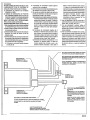
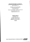
BLUE,YELLOW,WHITE,GREEN,ORANGE,
BLUE/WHITEc
SEEPOWERDOORLOCKSUPPLEMENT
ENCLOSED.
BLEU,JAUNE,BLANC,VERT,ORANGE,
BLEU/BLANC.
SE
REPORTER
AUSUPPLEMENT
PORTESA
VERROUILLAGE
ELECTRIQUE
CI-JOINT.
6-WIRECONNECTOR
CONNECTEUR
A 6 ALS
CONECTOR
DE6 AlAMBRES
VEA EL SUPLEMENTO
ADJUNTODE CERRADURAS
DE
POTENCIAPARAAZUL, AMARILLO,BLANCO,VERDE,
ANARANJADO
Y AZUL/BLANCO.
11011
~
~
~
15A FUSE (2)
FUSIBLE DE 15A (2)
FUSIBLE DE 15A (2)
-
~-.:~
d
2 WIRECONNECTOR,RED& BLACK WIRES.
PLUG INTO MAnNG 2 WIRE CONNECTOR
FROM ALARM.
CONNECTEUR
A 4 FILS
CONECTOR
DE4 ALAMBRES
CONNECTEUR A 2 FILS, FILS ROUGE ET
NOIR.BRANCHEZsURLECONNECTEURA
DEUX FILS CORREsPONDANTVENANTDE
L'ALARME.
REDCONNECT
TO REDWIREFROMALARMHARNESS.
LE ROUGESEBRANCHE
SURLE AL ROUGEDUHARNAISDEL'ALARME.
ROJOSECONECTA
AL CABLEROJODELCABLEADO
PREFORMADO
DELA
ALARMA.
CONECTOR DE DOS CABLES, CABLES
ROJO y NEGRO. CONECTE EN EL
CONECTOR DE EMPALME DE 2 CABLES
DE LA ALARMA.
BLACKTOCHASSIS
GROUND NOIRREUEA LA MASSEDUCHAsSIS
NEGROSECONECT
A A TlERRAENEl CHASIS
128-4177A
~
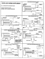
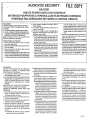
ALLALARMSWITH ON-BOARDRELAVS
WIRING
NORMAL
SCHEMATICS
LOCKI
FOR:
UNLOCK
OPERATION
---L...
.PIf
FROM
CONNECTOR
ALARMI(TERFACE
LOCK SWITCH
GROUNO
BLUE
-I
WJfTE
UNLOCK
WIRE
I
SPLx:E
/1
GREEN
~
CIJT
w
~
YEllOW
r
EXISTING
I
,
LOCK
WIRE
TO
.
DOOR
nIACE
TOSLAVEDOOR
LOCKSWJTCHES
LOCK
MOTOR
NEGATIVEPULSED DOOR LOCKS w/FACTORYALARM
OR CHILD PROOF LOCKS
r---'"\
DOOR
LOCK
SWITCH
~ LI1]r
~
BLUE(NOT
USED
I INSUlAm
T
LOCKWVIE
GROUND
YEllOW
UNLOCK
WVIE
I GREEN (NOT USED I INSUlATElI
WHITE
(2)W4OO1
DIOOES
~-
-' ~
BLUE/WHITE
ORANGE
TRACE
~
~
6 PIN CONNECTOR
FROM ALARM OR MERFACE
FACTORY SECURrry
WIRE FROM DOOR ,
KEY1WITCH OR DOOR LOCK:
MOTOR POSIT1ONSWTTCHWIRE
FOR \JjLOCK OVERRIDE
T
GROUND
/
PULSED12 VOLT LOCKI ALTERNATINGUNLOCK
PULSED GROUND UNLOCK/OPEN CIRCUrr LOCK
DOORLOCKSWITCH
EXIST1NG
DOOR
LOCK
SWITCH
BLUE w/WHITE TRACE
s PW CONNECTOR
~
AlARM
ORANGE
LOCK WIRE
i 6 PIN CONNECTOR
Ie,.-
MODULE
FROM
OR INTERFACE
UNLOCK
WIRE
~
YELLOW
YELLOW
j-
I BLU!~rrc
CUT
HERE
TRACE (IK)T USEDI ~TE)
WHfTE
BLUE
CUT EXISTWG ~
I UNLOCK WIRE
I
ORANGE
T
CUTEXISTING
LOCKIUNLOCKY:'RE