1
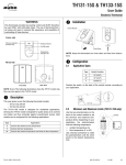
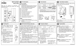
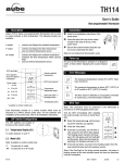
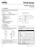
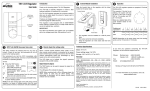
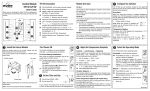
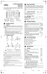
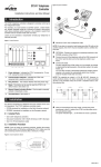
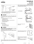
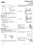
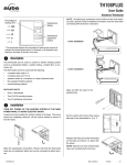
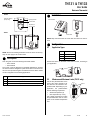
TH131 & TH133
User Guide
Electronic Thermostat
o
TH131
Pilot wire indicator
(Europe only)
Heating indicator
Installation
2.
Control Module
On/Off switch
Temperature
selection dial
TH133
Power Base
NOTE: Keep the thermostat's air vents clean and free from obstructions.
p
3.1
NOTE: Even if the following illustrations show the TH131 model only,
they can also apply to the TH133 model.
Description
1.
This user guide covers the following thermostat models:
• TH131 A/F/AF
• TH133 A/F/AF
The TH131 model is designed for residential applications, whereas
the TH133 model is designed for public areas as its controls are hidden and thus protected against unauthorized access. Both models
can be configured for the following applications:
Type
Application Types
Type
Switch Position
A
UP (A/AF)
AF
UP (A/AF)
F
DOWN (F)
Position the switch, on the back of the control module, according to
your application.
Application
A
Controls the ambient (room) temperature
F
Controls the floor temperature
AF
3.
Rear View
Front View
n
Configuration
Controls the ambient temperature and limits the floor temperature
3.2
Minimum and Maximum Limits (TH131 only)
Use the two potentiometers on the
back of the control module to set
the minimum and maximum temperature limits. Depending on your
application, the potentiometers
limit the following temperature:
notches
ambient temperature (A)
floor temperature (F or AF)
Use a flat-tip screwdriver to rotate
the potentiometers until the notch
points to the desired temperature
limit.
TH131 & TH133
400-131-002-C
1/11/06
1/2
q
4.1
Operation
4.
Temperature Adjustment
Use the dial on the front of the thermostat to set the desired temperature.
NOTE: If the dial is placed at a temperature beyond the high or low
temperature limit, the temperature will be maintained at that limit (see
section 3.2).
TH133
Remove the control module from the base and use the dial on the
back of the control module to set the desired temperature.
On/Off Switch (TH131 only)
Use the On/Off switch to turn the thermostat Off when it is not used
(e.g., in the summer).
r
Pilot Wire Orders (Europe only)
5.
TH131 accepts the six following pilot wire orders when installed on a
230 V power base.
ORDER
Comfort
SIGNAL
No signal
DESCRIPTION
Maintain temperature at setpoint
Reduced setpoint
(3.5k setback)
Maintain temperature at 3.5°C below
setpoint
frost protection
Maintain temperature at 7°C
Off
Stop heating
1k setback
Maintain temperature at 1°C below setpoint
2k setback
Maintain temperature at 2°C below setpoint
s
7.
AUBE TECHNOLOGIES INC. THREE (3) YEAR LIMITED WARRANTY
TH131
4.2
;
Warranty
Specifications
Setpoint range: 7°C, 15°C to 35°C (45°F, 59°F to 95°F)
Minimum temperature limit: 5°C to 25°C (41°F to 77°F)
Maximum temperature limit: 15°C to 35°C (59°F to 95°F)
6.
Aube warrants this product, excluding battery, to be free from defects
in the workmanship or materials, under normal use and service, for a
period of three (3) years from the date of purchase by the consumer.
If at any time during the warranty period the product is determined to
be defective or malfunctions, Aube shall repair or replace it (at Aube's
option).
If the product is defective,
(i) return it, with a bill of sale or other dated proof of purchase, to
the place from which you purchased it, or
(ii) contact Aube. Aube will make the determination whether the
product should be returned, or whether a replacement product
can be sent to you.
This warranty does not cover removal or reinstallation costs. This
warranty shall not apply if it is shown by Aube that the defect or
malfunction was caused by damage which occurred while the
product was in the possession of a consumer.
Aube's sole responsibility shall be to repair or replace the product
within the terms stated above. AUBE SHALL NOT BE LIABLE FOR
ANY LOSS OR DAMAGE OF ANY KIND, INCLUDING ANY
INCIDENTAL OR CONSEQUENTIAL DAMAGES RESULTING,
DIRECTLY OR INDIRECTLY, FROM ANY BREACH OF ANY
WARRANTY, EXPRESS OR IMPLIED, OR ANY OTHER FAILURE
OF THIS PRODUCT. Some regions do not allow the exclusion or
limitation of incidental or consequential damages, so this limitation
may not apply to you.
THIS WARRANTY IS THE ONLY EXPRESS WARRANTY AUBE
MAKES ON THIS PRODUCT. THE DURATION OF ANY IMPLIED
WARRANTIES,
INCLUDING
THE
WARRANTIES
OF
MERCHANTABILITY AND FITNESS FOR A PARTICULAR
PURPOSE, IS HEREBY LIMITED TO THE THREE-YEAR
DURATION OF THIS WARRANTY. Some regions do not allow
limitations on how long an implied warranty lasts, so the above
limitation may not apply to you.
This warranty gives you specific legal rights, and you may have other
rights which vary from region to region.
Customer Assistance
8.
If you have any questions about the product installation or operation,
or concerning the warranty, contact us at:
Accuracy: ± 0.2°C (0.36°F)
Storage: -20°C to 50°C (-4°F to 120°F)
Heating cycle length: 15 minutes
Software: Class A
Controller: Electronic
Size (H/W/D):
•
•
TH131: 78.9 x 78.9 x 16.3 mm (3.1 x 3.1 x 0.64 in.)
TH133: 78.9 x 78.9 x 18 mm (3.1 x 3.1 x 0.71 in.)
705 Montrichard
Saint-Jean-sur-Richelieu
Quebec, Canada J2X 5K8
Tel.: (450) 358-4600
Toll Free: 1-800-831-AUBE
Fax: (450) 358-4650
Email: [email protected]
10 rue Ampère
95500 Gonesse
France
Tel.: 33 (0) 1 34 07 99 00
Fax: 33 (0) 1 34 07 99 19
Email: [email protected]
For more information on our products, go to
www.aubetech.com
TH131 & TH133
400-131-002-C
1/11/06
2/2
PB130-024T
Installation Instructions
24-V Low-Voltage Power Base
n
Applications
1.
This document describes the connections when the PB130-024T
power base is used on any TH13x series thermostat. This
low-voltage power base can be connected to a line-voltage load
using a relay or directly to a 24-volt device. The PB130-024T is
compatible with most relays; however, the following Aube relays are
optimized for use with this power base:
•
RT850 solid-state relay (SSR)
•
RT850T solid-state relay (SSR) with built-in 24-V transformer
•
RC840 electromechanical relay
•
RC840T electromechanical relay with built-in 24-V transformer
o
n
o
p
Supplied Parts
4.1
Single SSR with Built-in Transformer
Electrical
Panel
Blue
Red
Black
4.2
Heater
Multiple SSRs with External Transformer
2.
One (1) power base
Electrical
Panel
Two (2) plastic anchors
Two (2) mounting screws
Black
p
Installation Guidelines
Heater
For a new installation, choose a location about 1.5 m (5 ft.)
above the floor.
The thermostat must be installed on an inside wall facing the
heating system (except for floor heating systems).
Avoid locations where there are air drafts (top of staircase, air
outlet), dead air spots (behind a door), direct sunlight or
concealed chimney or stove pipes (except for floor heating
systems).
q
Installation Procedure
o
p
q
r
s
t
u
Heater
4.3
Red
Electromechanical Relay with External Transformer
Electrical
Panel
4.
Turn off power to the heating system at the main electrical panel
to avoid electrical shock.
Wire the base according to your application. See typical wiring
diagrams in sections 4.1 to 4.4.
External 24 V
Transformer
Heater
4.4
Hot Water Heater Valve
Electrical
Panel
For a floor heating system installation, connect the floor sensor between the S and R terminals.
Secure the base to the wall using the provided screws and wall
anchors.
Configure the switches located on the control module (if any).
Refer to the user guide.
Install the control module onto the base.
Apply power to the heating system.
Verify the installation by checking that the heating system can be
turned On or Off using the thermostat.
PB130-024T
Red
Black
The installation must be carried out by an electrician and must
comply to local electrical codes.
n
External 24 V
Transformer
3.
External 24 V
Transformer
r
Valve
Technical Specifications
5.
Maximum load: 0.5 A / 24 VAC
Operating temperature: 0°C to 50°C (32°F to 122°F)
Storage: -20°C to 50°C (-4°F to 122°F)
Size (H • W • D): 75 x 75 x 13 mm (2.9 x 2.9 x 0.5 in)
Wire gauge: 14 to 22 AWG
400-130-002-C
1/11/06
1/1