1
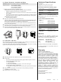
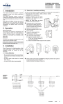
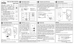
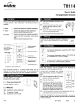
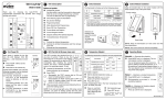
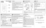
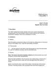
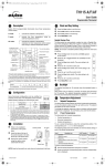
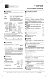
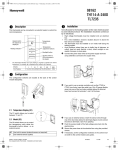
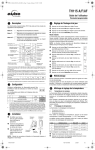
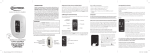
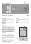
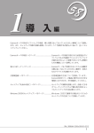
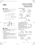
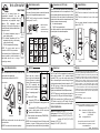
TH1 1 3 & TH1 1 6 A/F/AF
Owner s Guide
Thank you for choosing Aube’s nonprogrammable thermostat. Your new
electronic thermostat is equipped with a
microprocessor and proportional integral
adaptive
(PIA)
temperature
control
technology for total comfort. Depending on
the selected model, this thermostat has been
designed to control:
A: The Ambient temperature (using an
electric heating system)
AF: The Ambient temperature with Floor
temperature limit (using a floor heating
system to heat the room)
F: The Floor temperature (floor heating)
Model Selection (switch)
Temperature Lock (TH1 1 3 only)
FOR A AND AF MODELS ONLY
At the rear of the control module is a switch that has been
factory-set to the applicable temperature control.
NOTE: The AF model can be used for all temperature
control types (A, F and AF).
Note: The ambient
sensor is not
operational when the
switch is set to I (up).
At the rear of the control module are two potentiometers.
These potentiometers act like a temperature lock. Even
when occupants adjust the temperature using the dial on
the front/rear of the control module, the potentiometers
override the dial and maintain the temperature within the
locked-in minimum and maximum range.
A - ambient temperature
F & AF - floor temperature limit
Use a flat tip screwdriver to rotate the potentiometers until
the notch points to the desired temperature.
Setpoint Definition
Turn the dial to the desired temperature.
TH113: The dial is located on the front of the control
module.
TH116: The dial is located on the rear of the control
module.
The min. position indicates the minimum temperature
setpoint: 45°F (7°C).
TH116
Temperature
dial
Public Area
Potentiometers
Notch
NOTE: This control module must be
mounted on a PB112 Series power base.
The thermostat has an On/Standby switch
making it possible to put the thermostat in
sleep mode when its use is no longer
required (e.g. summer).
TH113
Control Module Installation
Align the bracket tabs on the control module with the
holes located on the power base.
Follow the same procedure for the TH116.
Control module
TH113
GFCI Test ߺ ߴߓ ߙߓ ߺ ߵߓ ࠣࠢࠪ࠘ࠥߓ ࠕࠔࠦ࠘ߓ ࠢࠡ ࠟ ࠬ
The GFCI monitors the electrical
flow for any loss of current; if
there is any loss, the thermostat
will cut off power to the heating
system. We recommend you test
the GFCI immediately after
installing the control module, and
once a month thereafter to
ensure it is operating properly. To
test:
! Press the TEST button:
• Successful: TEST warning light is ON and power to heating system is cut
off.
• Unsucessful: The TEST warning light is OFF. Cut
power to heating system from the main power
panel and call customer service.
Power base
" When successful, reset thermostat (STANDBY/ON)
to power heating system.
NOTE: Keep the thermostat's air vents clean and free
from obstructions.
NOTE: The screw cannot be removed completely.
NOTE: If the test warning light comes ON during normal
operation, cut power to heating system from the main
power panel and have an electrician verify the installation.
Remote Input
The TH113 and TH116 are equipped with a remote input
which allows connection of an optional telephone
controller (CT240) or any other remote control system.
When a command signal is received through this input,
the thermostat automatically lowers its setpoint by 3.5°C.
The LED lights up to indicate the signal’s presence
(except for GA and GB models).
Bypass (not available for GA and GB power base):
The TEST button can be used to bypass the signal for a
2-hour period. The LED goes off to indicate the bypass.
NOTE: When combined with a GA/GB power base, the
TEST button is used only for GFCI testing. The bypass
function is not available with these power base models.
Technical Specifications
Models: TH113 and TH116 A / AF / F
Setting range: 45°F, 59°F to 95°F (7°C, 15°C to 35°C)
Potentiometers: minimum: 41°F to 77°F (5°C to 25°C)
maximum: 59°F to 95°F (15°C to 35°C)
Accuracy: ± 0.9°F (0.5°C)
Storage: -4°F to 120°F (-20°C to 50°C)
TH116
Warranty
AUBE TECHNOLOGIES INC. ONE (1) YEAR LIMITED WARRANTY
This product is guaranteed against workmanship defects for a one year
period following the initial date of purchase. During this period, AUBE
Technologies Inc. will repair or replace, at our option and without charge,
any defective product which has been used under normal conditions. The
warranty does not cover delivery costs and does not apply to products
poorly installed or randomly damaged following installation. This warranty
cancels and replaces any other manufacturer's express or implied
warranty as well as any other company commitment. AUBE Technologies
Inc. cannot be held liable for related or random damages following the
installation of this product. The defective product as well as the purchase
invoice must be returned to the place of purchase or mailed, prepaid and
insured, to the following address:
Aube Technologies Inc.
705 Montrichard
Saint-Jean-sur-Richelieu, Quebec, Canada J2X 5K8
If you have any questions concerning the TH113 or the TH116
thermostat, call our technical support team at:
Phone:
Fax:
Email:
Montreal area: (450) 358-4600
Canada / U.S.: 1-800-831-AUBE (2823)
y(450) 358-4650
[email protected]
Monday to Friday from 8:30 AM to 5:00 PM EST.
For more information on our products, visit us at:
www.aubetech.com
01/08/03
920-113-001-00-1-A
Installation Instructions
MASTER THERMOSTATS
TH113-A/F/AF (12VDC)
TH114-A/F/AF (12VDC)
TH115-A/F/AF (12VDC)
TH116-A/F/AF (12VDC)
1. Introduction
This master and slave unit system is specially
designed for large floor heating applications
exceeding 15 A.
The master thermostat controls a single or
multiple floor heating zones driven by slave units.
The master thermostat can control up to 10 slave
units.
Each slave unit drives its own zone and is
equipped with a GFCI test button and warning
light as well as an On/Standby switch to facilitate
maintenance on specific zones of the floor
installation.
2. Operation
Master Thermostat
The master unit controls the temperature and
sends a signal to slave units when heating is
required. The floor sensor is connected to the
master unit. The master unit is powered by the
slave units.
SLAVE UNITS
CT230-120GA
CT230-120GB
CT230-240GA
CT230-240GB
3.2 Slave Units - Installation and Wiring
The slave units can operate on different voltages (e.g. 5 units @ 120 V and 5 @ 240 V).
• Required parts: CT230-120GA, -120GB, -240GA or -240GB
• Installation: On an electrical box
• Location: Installation near the master
thermostat is not required (i.e. can be
installed in a utility room).
• Wiring: The power bases are joined
through a daisy chain connection.
n
Connect the 120 V or 240 V power
base wires to the power (line) and to
the load (floor) using solderless connectors for copper wires, and secure
the base to the electrical box.
o
Affix the wiring sticker (in the CT230
box) to the base.
p
Connect the slave power bases
together as per FIGURE 1.
q
Once installation and wiring is complete, mount the CT230 interface:
a) Align the bracket tabs of the
CT230 with the holes located on
top of the power base.
b) Secure the CT230 interface using the screw (captive).
r
Switch all slave power bases to STANDBY by sliding the protective door upwards
and positioning the switch to STANDBY.
Install and connect the master unit (see 3.3).
Slave Unit
The slave unit receives the signal sent by the
master unit and activates its load.
NOTE: There must be a minimum of one slave
unit ON to power the master unit.
3. Installation
Turn off power to the heating system at the
main power panel to avoid electrical shock.
Installation should be carried out by an
electrician.
3.1 Wiring Guidelines
• The wire distance between the master thermostat and slave unit should not exceed 500 ft.
(150 m).
• The floor sensor cable should not exceed
200 ft. (60 m).
• A 3-wire 20 AWG cable is recommended.
FIGURE 1
Connections
400-230-000-C
5/12/05
1/2
3.3 Master Thermostat - Installation and Wiring
Technical Specifications
WARNING: Make sure all slave units are in STANDBY mode.
Temperature:
- Operation: 32°F to 122°F (0°C to 50°C)
- Storage: -4°F to 122°F (-20°C to 50°C)
•Required parts:
TH113-A/F/AF (12VDC),
TH114-A/F/AF (12VDC),
TH115-A/F/AF (12VDC) or
TH116-A/F/AF (12VDC)
• Location: anywhere easily accessible to users.
Temperature control: AF (ambient with floor limit) / A (ambient)
•
Install the master thermostat in the controlled area.
•
Choose a location about 5 ft. above the floor in an area where the temperature is stable.
•
Avoid locations where there are air drafts (top of staircase, air outlet), dead air
spots (behind a door), direct sunlight or concealed chimneys or stove pipes.
Temperature control: F (floor)
•
s
Can be installed anywhere.
Wire the 12 VDC base to the nearest slave unit.
The floor sensor must be installed in an area where average temperature can be
read. The cable must follow the wall down to the floor and must not cross any
heater wires or be directly on or adjacent to a heating wire.
For maximum performance, the sensor probe should be centered between the
wires in the mat (max. 80°C).
t
Push the excess wire into the wall, secure the base using the provided screws
and wall anchors, and install the TH11x thermostat onto the base.
u
Once the thermostat is installed, return power to heating system and switch all
slave units and the master thermostat to ON.
TH113/TH114/TH115/TH116 (A/F/AF-12VDC)
Power supply
12 V from remote unit
Maximum
slave units
up to 10 slave units per
master thermostat
Wire gauge
20 AWG
Size (H • W • D)
BASE
4.63 x 2.7 x 0.61 in.
(117.5 x 68.3 x 15 mm)
NOTE: Refer to the TH11x user guide for technical specifications.
CT230-120GA/120GB/240GA/240GB
Supply
- PB112-120
- PB112-240
1800 W @ 120 VAC
60 Hz, 15 A resistive
3600 W @ 240 VAC
60 Hz, 15 A resistive
GFCI
GA=5 mA / GB=30 mA
Certification
c CSA us
Size (H • W • D)
BASE
4.63 x 2.7 x 1.45 in.
(117.5 x 68.3 x 37 mm)
Size (H • W • D)
INTERFACE
4.67 x 2.74 x 0.67 in.
(118.6 x 69.6 x 17 mm)
Service
If you have any questions concerning the
installation of the master thermostat or slave
units, contact our technical support team at:
3.4 Slave Units - GFCI Test
We recommend you test the GFCI immediately after installing the thermostat, and
once a month thereafter to ensure it is operating properly.
If the test warning light comes ON during normal operation, cut power to heating
system from the main power panel and verify the installation.
Montreal area:
Canada / U.S.:
Fax:
Email:
(450) 358-4600
1-800-831-AUBE (2823)
(450) 358-4650
[email protected]
Monday to Friday from 8:30 AM to 5:00 PM EST.
For more information on our products, visit us at
www.aubetech.com
Warranty
n
o
Slide the protective door upwards and make sure the switch is ON.
Press TEST.
•
The test is successful if the TEST warning light is ON and power is cut off.
•
If the test fails (first installation test):
a. Verify installation
b. Check the load wires
c. Once you've identified the problem, run the GFCI test again
•
If the test fails (monthly maintenance):
a. Cut power to heating system from the main power panel and call customer
service
p
When the test is successful, reset the slave unit by switching from ON to
STANDBY then back to ON.
q
Repeat steps 1 to 3 for all slave units.
AUBE TECHNOLOGIES INC.
ONE (1) YEAR LIMITED WARRANTY
This product is guaranteed against workmanship
defects for a one year period following the initial
date of purchase. During this period, AUBE
Technologies Inc. will repair or replace, at our
option and without charge, any defective product
which has been used under normal conditions.
The warranty does not cover delivery costs and
does not apply to products poorly installed or
randomly damaged following installation. This
warranty cancels and replaces any other
manufacturer's express or implied warranty as
well as any other company commitment.
AUBE Technologies Inc. cannot be held liable for
related or random damages following the
installation of this product. The defective product
as well as the purchase invoice must be returned
to the place of purchase or mailed, prepaid and
insured, to the following address:
Aube Technologies Inc.
705 Montrichard
Saint-Jean-sur-Richelieu, Quebec,
Canada J2X 5K8
400-230-000-C
5/12/05
2/2