1
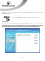
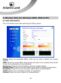
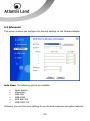
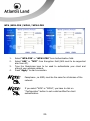
ITALIANO
Questo prodotto è coperto da garanzia Atlantis Land della durata di 2 anni. Per
maggiori dettagli in merito o per accedere alla documentazione completa in Italiano
fare riferimento al sito www.atlantis-land.com.
ENGLISH
This product is covered by Atlantis Land 2 years warranty. For more detailed
informations please refer to the web site www.atlantis-land.com.
For more detailed instructions on configuring and using this device, please refer to the
online manual.
FRANCAIS
Ce produit est couvert par une garantie Atlantis Land de 2 ans. Pour des informations
plus détaillées, référez-vous svp au site Web www.atlantis-land.com.
DEUTSCH
Dieses Produkt ist durch die Atlantis Land 2 Jahre Garantie gedeckt. Für weitere
Informationen, beziehen Sie sich bitte auf Web Site www.atlantis-land.com.
ESPAÑOL
Este producto esta cubierto por Atlantis Land con una garantía de 2 años. Para mayor
información diríjase a nuestro sitio Web www.atlantis-land.com.
ENGLISH
1. Introduction ....................................................................................................... 8
2. Unpacking and setup .......................................................................................... 8
2.1 Unpacking……………………………………………………………………………………………….8
2.2 Setup………………………………………………………………………………………………………8
3. Hardware Installation ......................................................................................... 9
3.1 LED Indicator ............................................................................................. 9
3.2 Check the installation .................................................................................. 9
4. Software Installation........................................................................................... 9
4.1 Utility and driver installation for OS Windows................................................ 9
4.2 Check the installation .................................................................................10
5. Wireless Utility (For Windows VISTA)..................................................................12
5.1 Link Info…………… ......................................................................................12
5.2 Configuration.............................................................................................13
5.3 Site Survey. ...............................................................................................16
5.4 Profile……… ...............................................................................................17
5.5 About………................................................................................................18
6. Wireless Uility (for Windows 98SE, 2000 ed XP) ..................................................19
6.1 Link Information ........................................................................................19
6.2 Configuration.............................................................................................20
6.3 Advanced….. .............................................................................................23
6.4 Site Survey.. ..............................................................................................26
6.5 About………................................................................................................27
7. Support ............................................................................................................28
8. APPENDIX A: Technical Specifications .................................................................29 A02-PCI-W54(v1.2)_ME01 (v1.1 Mar 2009)
3
Copyright Statement
No part of this publication may be reproduced, stored in a retrieval system, or
transmitted in any form or by any means, whether electronic, mechanical,
photocopying, recording or otherwise without the prior writing of the publisher.
Windows™ 98SE/2000/ME/XP/VISTA are trademarks of Microsoft® Corp. Pentium is
trademark of Intel. All copyright reserved.
The Atlantis Land logo is a registered trademark of Atlantis Land. All other names
mentioned mat be trademarks or registered trademarks of their respective owners.
Subject to change without notice. No liability for technical errors and/or omissions.
Wireless LAN, Health and Authorization for use
Radio frequency electromagnetic energy is emitted from Wireless LAN devices. The
energy levels of these emissions however are far much less than the electromagnetic
energy emissions from wireless devices like for example mobile phones. Wireless LAN
devices are safe for use frequency safety standards and recommendations. The use of
Wireless LAN devices may be restricted in some situations or environments for
example:
·On board of airplanes, or
·In an explosive environment, or
·In case the interference risk to other devices or services is perceived or identified as
harmful
In case the policy regarding the use of Wireless LAN devices in specific organizations
or environments (e.g. airports, hospitals, chemical/oil/gas industrial plants, private
buildings etc.) is not clear, please ask for authorization to use these devices prior to
operating the equipment.
Regulatory Information/disclaimers
Installation and use of this Wireless LAN device must be in strict accordance with the
instructions included in the user documentation provided with the product. Any
changes or modifications made to this device that are not expressly approved by the
manufacturer may void the user’s authority to operate the equipment. The
Manufacturer is not responsible for any radio or television interference caused by
unauthorized modification of this device, of the substitution or attachment.
Manufacturer and its authorized resellers or distributors will assume no liability for any
damage or violation of government regulations arising from failing to comply with
these guidelines.
4
Copyright Statement
No part of this publication may be reproduced, stored in a retrieval system, or
transmitted in any form or by any means, whether electronic, mechanical,
photocopying, recording or otherwise without the prior writing of the publisher.
Windows™ 98SE/2000/ME/XP/VISTA are trademarks of Microsoft® Corp. Pentium is
trademark of Intel. All copyright reserved.
The Atlantis Land logo is a registered trademark of Atlantis Land. All other names
mentioned mat be trademarks or registered trademarks of their respective owners.
Subject to change without notice. No liability for technical errors and/or omissions.
Wireless LAN, Health and Authorization for use
Radio frequency electromagnetic energy is emitted from Wireless LAN devices. The
energy levels of these emissions however are far much less than the electromagnetic
energy emissions from wireless devices like for example mobile phones. Wireless LAN
devices are safe for use frequency safety standards and recommendations. The use of
Wireless LAN devices may be restricted in some situations or environments for
example:
•
On board of airplanes, or
•
In an explosive environment, or
•
In case the interference risk to other devices or services is perceived or
identified as harmful
In case the policy regarding the use of Wireless LAN devices in specific organizations
or environments (e.g. airports, hospitals, chemical/oil/gas industrial plants, private
buildings etc.) is not clear, please ask for authorization to use these devices prior to
operating the equipment.
Regulatory Information/disclaimers
Installation and use of this Wireless LAN device must be in strict accordance with the
instructions included in the user documentation provided with the product. Any
changes or modifications made to this device that are not expressly approved by the
manufacturer may void the user’s authority to operate the equipment. The
Manufacturer is not responsible for any radio or television interference caused by
unauthorized modification of this device, of the substitution or attachment.
Manufacturer and its authorized resellers or distributors will assume no liability for any
damage or violation of government regulations arising from failing to comply with
these guidelines.
5
CE Mark Warning
In a domestic environment, this product may cause radio interference, in which case
the user may be required to take adequate measures.
CE in which Countries where the product may be used freely:
Germany, UK, Italy, Spain, Belgium, Netherlands, Portugal, Greece, Ireland, Denmark,
Luxembourg, Austria, Finland, Sweden, Norway and Iceland.
France: except the channel 10 through 13, law prohibits the use of other channels.
CE/EMC Restriction of Liability
The product described in this handbook was designed, produced and approved
according to the EMC-regulations and is certified to be within EMC limitations.
If the product is used in an uncertified PC, the manufacturer undertakes no warranty
in respect to the EMC limits. The described product in this handbook was constructed,
produced and certified so that the measured values are within EMC limitations. In
practice and under special circumstances, it may be possible, that the product may be
outside of the given limits if it is used in a PC that is not produced under EMC
certification. It is also possible in certain cases and under special circumstances,
which the given EMC peak values will become out of tolerance. In these cases, the
user himself is responsible for compliance with the EMC limits.
Declaration of Conformity
This equipment has been tested and found to comply with Directive 1999/5/CE of the
European Parliament and of the Council on radio equipment and telecommunications
terminal equipment and the mutual recognition of their conformity. After assessment,
the equipment has been found to comply with the following standards: EN 300.328
(radio), EN 301 489-1, EN 301 489-17 (electromagnetic compatibility) and EN 60950
(safety). This equipment may be used in all European Union contries and in all
countries applying Directive 1999/5/CE, without restriction, with the exception of the
following countries:
France (FR): When this equipment is used outdoors, output power is limited to within
the frequency bans listed on the chart. For more info, consult the website www.arttelecom.fr.
Location
Indoor (no restriction)
Frequency Band (MHz)
2400-2483,5
6
Power (EIRP)
100mW(20dBm)
Outdoor
2400-2454
100mW(20dBm)
2454-2483,5
10mW(10dBm)
Italy(IT): For more info, consult the website www.comunicazioni.it
Luxembourg: General authorization requie for network and service supply.
Norway (NO): This subsection does not apply for geographical area within a radius
of 20 km from the center of Ny Alesund.
Russia (CCP): only for indoor application.
Declaration of Conformity
Hereby, Sidin SpA, declares that this product (A02-PCI-W54) is in compliance to all
relevant essential requirements of R&TTE Directive (99/5/CE). CE Declaration is
available on the web site www.atlantis-land.com.
7
Congratulations on your purchase of this 802.11g Wireless PCI Adapter. This manual
helps to get familiar with the Adapter. This manual contains detailed instructions in
operation of this product. Please keep this manual for future reference.
1. Introduction
With a Wireless LAN (IEEE 802.11g) PCI Adapter, a desktop or laptop computer can
communicate with another computer in a wireless way. Easy-to-use utilities are
bundled with Wireless USB Adapter for configuration, monitoring, and diagnosis
purposes. The Adapter can wirelessly transmit and receive data, minimizing the need
for wired connections, at a speed of up to fiftyfour megabit per second. The Adapter
provides users with an access to real-time information anywhere in their organization.
The mobility provides productivity and service, which are not available under wired
networks. The Adapter configuration is easy to change from peer-to-peer networks,
suitable for a small number of users, to full infrastructure networks of thousands of
users that allow roaming around a broad area.
2. Unpacking and setup
This chapter provides unpacking and setup information for the Wireless Adapter.
2.1 Unpacking
Open the box of the Wireless Adapter and carefully unpack it. The box should contain
the following items:
•
•
•
•
1
1
1
1
x
x
x
x
NetFly PCI 54
2.2dBi dipole detacheable antenna (R-SMA connector)
Multilanguage QuickStart Guide (English and Italian)
CDRom with driver, utility and online manual
If any item is found missing or damaged, please contact your local reseller for
replacement.
2.2 Setup
The setup of the Wireless LAN Adapter can be performed using the following steps:
8
•
•
Visually inspect the PCI Adapter and make sure that it is fully plugged in to
the PCI slot.
Make sure that there is a well environment that there is no much intrusion
to have a better connection.
3. Hardware Installation
3.1 LED Indicator
LINK: The Link LED indicator lighted green when the Wireless Adapter is connected to
wireless network successfully.
3.2 Check the installation
The LEDs of the Wireless LAN Adapter are clearly visible and the status of the network
link can be seen instantly:
•
•
•
Once the device is plugged to the station’s PCI slot, the LED of the
Wireless LAN Adapter will light up indicating a normal status.
When the device plugged to the station’s PCI slot and the driver was
installed, the ACT will start alternate blinking, it means that the device is
starting to scan the wireless devices near the Wireless LAN Adapter.
While the Wireless LAN Adapter linked up and transmitting data to the
Access Point or to other Wireless LAN station, the Link LED will lighted
green.
4. Software Installation
4.1 Utility and driver installation for OS Windows
1.
Insert the CD-ROM and the Auto-run program will appear. Alternatively,
open a file browser and double click on the autorun.exe file located in the
CD directory. In some specific setting on Windows system, you may need
to proceed the software manually, go to your Windows Start menu and
choose
Run,
type
“D:\A02-PCIW54\UTILITY\<OSVer>\SETUP.EXE” in the dialog box and click OK.
9
D:\ will depends on where the CD-ROM drive is located and
<Windows OS> will depend on the Windows OS you are using.
2.
3.
Click on “A02-PCI-W54” icon to select Wireless USB Adapter Home Page.
Select “Windows 98/2000/XP Utility” or “Windows VISTA Utility”,
depending on your operating system, and the install wizard will begin
installing the software. Follow the install wizard instructions to complete
the installation.
If you need to install the driver manually, refer each Windows
OS to the following CD-Rom directory path: D:\A02-PCIW54\Driver\<Windows OS>.
D:\ will depends on where the CD-ROM drive is located and
<Windows OS> will depend on the Windows OS you are using.
4.2 Check the installation
Be noted that the Windows XP have its own Wireless Utility;
you can either use the utility of Windows XP or the provided
utility.
When the Wireless LAN Adapter was installed, you will see the icon on the Windows
task bar. The user can configure the wireless settings using the Wireless Adapter
Configuration Utility. Double-click the utility icon that appears in the taskbar
Icon
Quality of Signal
Excellent
10
Good
Waiting connection
Not connected
When the icon in the toolbar represents in full green color then the signal strength has
an excellent performance with the AP, if it represents in yellow color then the signal
strength has a fair performance with the AP, and if the icon represents no color, then
the signal strength has a worst performance with the wireless station.
11
5. Wireless Utility (For Windows VISTA)
5.1 Link Info
This is the default screen after launching the Utility program.
Status: Shows the associated BSSID, which can be used to identify the wireless
access point.
SSID: Shows the current SSID, which must be the same on the wireless client and AP
in order for communication to be established.
Wireless Mode: Shows the current wireless mode used for wireless communication.
Encryption: Hoes the current encryption mode used on the wireless network.
TX Rate: Shows the current data rate used for transmitting.
Channel: Shows the current channel for communication.
Signal Strength of Percentage: Shows the wireless signal strength of the
12
connection between the Wireless LAN USB 2.0 Adapter with the Access Point.
TX/RX: Shows the statistics of data transfer, and the calculation is based on the
number of packets transmitted and received. It also shows the link quality of the
Wireless LAN USB 2.0 Adapter with the Access Point when operation under
Infrastructure mode.
5.2 Configuration
This screen is where you set the basic wireless settings for the Wireless LAN USB 2.0
Adapter.
Segue una descrizione delle opzioni selezionabili:
Profile Name: The default name is the same as the SSID of the platform which you
connected and you can change the name you favor( the key length is limited 1~32
bits).
13
SSID: Service Set Identifier, which is a unique name shared among all client in a
wireless network. The SSID must be identical for client in the wireless network.
Wireless Mode: There are two modes available for this selection:
•
•
Infrastructure: to establish wireless communication with the LAN and
other wireless client through the use of Access Points.
Ad-Hoc: to establish point- to-point wireless communication directly with
other wireless client device.
Authentication: The following options are available:
•
•
•
•
•
•
Open System
Shared key
WPA-PSK
WPA2-PSK
WPA EAP-TLS
WPA2 EPA-TLS
Following, you can find some settings to use the most commons ecnryption features.
OPEN SYSTEM / SHARED KEY
1.
2.
Select “Open System” or “Shared System” from Authentication field.
Select “WEP” from Encryption field. (Wired-Equivalent Protection).
14
3.
4.
5.
Select “ASCII” of “HEX” from Key Format to choose keys introducing
method.
Type 4 keys (64 or 128 bits) to use to encrypt your data with WEP and
check which one you’d use.
Press “Apply” to start connection.
WEP key, as SSID, must be the same for all devices of the
network.
WPA /WPA-PSK / WPA2 / WPA2-PSK
1.
2.
3.
4.
Select “WPA-PSK” or “WPA2-PSK” form Authentication field.
Select “AES” or “TKIP” from Encryption field (AES must to be supported
also from AP).
Type the Passphrase keys to be used to authenticate your client and
encrypt your wireless network.
Press “Apply” to start connection.
15
Passphrase , as SSID, must be the same for all devices of the
network.
If you need to use a RADIUS authentication, please choose
“WPA” or “WPA2” and select which type of certificate do you
use for authentication.
5.3 Site Survey
This screen displays the wireless networks (wireless clients and Access Points) that are
within range and it also allows the user to establish wireless communications with an
available wireless network.
16
Select any one of the wireless networks by double-clicking on it or clicking on the
“Connect” button.
Click on “Refresh” to update available wireless networks.
5.4 Profile
The user can create and manage the created profiles for home, work or public areas.
By double-clicking on one of the created profile, the setting will adjust to the specific
setting such as SSID, channel, and encryption as saved by that particular profile.
17
Add: Adds a profile. The following screen will appear. The user can enter the
necessary information required for accessing Access Points or Wireless Router.
Remove: Deletes the selected profile
Edit: To view and change its settings of the profile.
Connect: The current connected profile information
5.5 About
This screen displays information about the Wireless Adapter, such as the Driver and
Utility version. When a new version of the utility becomes available for upgrade, users
will be able to identify by version numbers.
18
6. Wireless Uility (for Windows 98SE, 2000 ed XP)
6.1 Link Information
This is the default screen after launching the Utility program.
Status: Shows the associated BSSID, which can be used to identify the wireless
network.
SSID: Shows the current SSID, which must be the same on the wireless client and AP
in order for communication to be established.
Frequency: Shows the current frequency used for wireless network.
Wireless Mode: Shows the current wireless mode used for wireless communication.
Encryption: Shows the current encryption mode used for wirelessnetwork.
TxRate: Shows the current data rate used for transmitting.
Channel: Shows the current channel for communication.
19
Link Quality: Shows the link quality of the wireless LAN adapter with the Access
Point when operating under Infrastructure mode.
Signal Strength: Shows the wireless signal strength of the connection between the
wireless LAN adapter card with the Access Point.
Data Rate: Shows the statistics of data transfer, and the calculation is based on the
number of packets transmitted and received.
6.2 Configuration
This screen is where changes the basic wireless settings for the wireless LAN adapter
with the minimum amount of effort to implement a secure wireless network
environment.
SSID: Service Set Identifier, which is a unique name shared among all clients and
nodes in a wireless network. The SSID must be identical for each clients and nodes in
the wireless network.
20
Wireless Mode: There are two types available for selection:
•
•
Infrastructure: to establish wireless communication with LAN and other
wireless clients through the use the Access Points.
Ad-Hoc: to establish point-to-point wireless communication directly with
other wireless client devices such as wireless network PCI Adapter.
o
AdHoc Band: When using Wireless Mode for Ad-Hoc mode,
select the AdHoc Band from drop down list for 11b only, 11g
only or Auto for both of 11b and 11g (tra 11g only, 11b only
e Auto)
o
Channel: The channel the AP operates on. The channel range
of 1 to 11 for North America (FCC) domain and 1 to 13 for
European (ETSI) domain and 1 to 14 for Japanese domain.
Country domain can't be choose by enduser, because the
incorrect region may be in violation of applicable laws.
Power Mode: There are 3 modes to choose from:
•
•
•
Continuous Access Mode (default): the wireless LAN adapter is
constantly operating with full power. This mode consumes the most power.
Maximum Power Save: the wireless LAN adapter consumes the least
power. This mode only operates when there is wireless network activity.
Power Save: the wireless LAN adapter consumes moderate level of
power.
Preamble Type: Select Long or Short Preamble type. Preamble is a sequence of bits
transmitted at 1Mbps that allows the PHY circuitry to reach steady-state demodulation
and synchronization of bit clock and frame start. Two different preambles and headers
are defined: the mandatory supported Long Preamble and header, which interoperate
with the 1 Mbit/s and 2 Mbit/s DSSS specification (as described in IEEE Std 802.11),
and an optional Short Preamble and header (as described in IEEE Std 802.11b). At the
receiver, the Preamble and header are processed to aid in demodulation and delivery
of the PSDU. The Short Preamble and header may be used to minimize overhead and,
thus, maximize the network data throughput. However, the Short Preamble is
21
supported only from the IEEE 802.11b (High- Rate) standard and not from the original
IEEE 802.11. That means that stations using Short-Preamble cannot communicate with
stations implementing the original version of the protocol. Click “Apply” for the
changes to take effect.
Support Band: There are two modes the user can select, including 11B and 11G. The
default setting is 11B and 11G are enabled, which is interoperable with both 11B and
11G devices.
User must select one of 11B or 11G at least; otherwise the
wireless connection will not function
22
6.3 Advanced
This screen is where you configure the Security settings for the Wireless Adapter.
Auth Mode: The following options are available:
•
•
•
•
•
•
Open System
Shared key
WPA-PSK
WPA2-PSK
WPA EAP-TLS
WPA2 EPA-TLS
Following, you can find some settings to use the most commons ecnryption features.
23
OPEN SYSTEM / SHARED KEY
1.
2.
3.
4.
5.
Select “Open System” or “Shared System” from Authentication field.
Select “WEP” from Encryption field. (Wired-Equivalent Protection).
Select “ASCII” of “HEX” from Key Format to choose keys introducing
method.
Type 4 keys (64 or 128 bits) to use to encrypt your data with WEP and
check which one you’d use.
Press “Apply” to start connection.
WEP key, as SSID, must be the same for all devices of the
network.
24
WPA /WPA-PSK / WPA2 / WPA2-PSK
1.
2.
3.
4.
Select “WPA-PSK” or “WPA2-PSK” form Authentication field.
Select “AES” or “TKIP” from Encryption field (AES must to be supported
also from AP).
Type the Passphrase keys to be used to authenticate your client and
encrypt your wireless network.
Press “Apply” to start connection.
Passphrase , as SSID, must be the same for all devices of the
network.
If you select “WPA” or “WPA2”, you have to click on
“Configuration” button to set a valid certified for client
authentication.
25
6.4 Site Survey
This screen displays the wireless networks (wireless clients and Access Points) that are
within range and it also allows the user to establish wireless communications with an
available wireless network.
Select any one of the wireless networks by double-clicking on it or clicking on the
“Connect” button.
Click on “Refresh” to update available wireless networks.
26
6.5 About
This screen displays information about the Wireless Adapter, such as the Driver and
Utility version. When a new version of the utility for upgrade, users will be able to
identify by version numbers.
27
7. Support
For
technical
informations,
please
connect
to
http://www.atlantisland.com/ita/supporto.php for use on-line ticket platform or call +39 02 00 632 345.
For general informations: [email protected]
For presale informations: [email protected]
Atlantis Land
Via Pelizza da Volpedo, 59
20092 Cinisello Balsamo (MI) - Italy
Tel: +39. 02.00.632.300
Fax: +39. 02.66.016.666
Website: http://www.atlantis-land.com
Email: [email protected]
28
8. APPENDIX A: Technical Specifications
General
Radio Technology
Interface
Data Transfer Rate
Receiver Sensitivity
Frequency Range
Modulation Schemes
Channels
Media
Access
Protocol
Security
Diagnostic LED
Antenna
Driver Support
Continuos Current
Consuption
IEEE 802.11b Direct Sequence Spread Spectrum
(DSSS)
IEEE 802.11g Orthogonal Frequency Division
Multiplexing (OFDM)
PCI 32-bit
1, 2, 5.5, 6, 9, 11, 12, 18, 24, 36, 48, 54Mbps
802.11g: Typical -72dBm @ 10% PER
802.11b: Typical -85dBm @ 8% PER
2412 ~ 2472 MHz ISM band (channels 1 ~ 13)
DBPSK/DQPSK/CCK/OFDM
1~13 channels (ETSI)
CSMA/CA with ACK
64/128-bits WEP, WPA-PSK, WPA2-PSK, WPA, WPA2
Link
2.2dB dipole antenna
Windows 98, ME, Windows 2000, Windows XP,
Windows Vista
370 mA (Rx), 470 mA (Tx)
Physical and Environmental
Temperature
Humidity
Dimensions
Certifications
Operating: 0° ~ 40° C, Storage: -10° ~ 70° C
10% ~ 95% RH, no condensation
131 x 121 x 21.6 mm (without antenna)
CE (Europe), WHQL Driver Certification
All rights registered
Microsoft and Windows are registered trademarks of Microsoft Corporation
All trade names and marks are registered trademarks of respective companies
Specifications are subjected to change without prior notice. No liability for technical
errors and/or omissions
29
30
Via Pelizza da Volpedo, 59
Cinisello Balsamo – MI – Italy
[email protected]