1
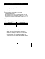
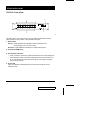
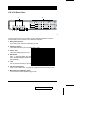
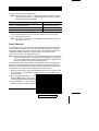
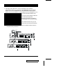
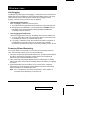
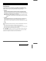
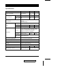
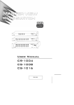
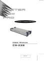
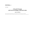
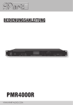
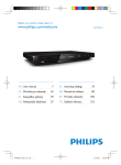
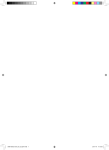
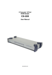
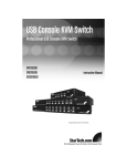
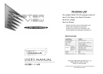
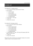
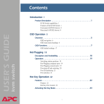
User Manual CS-1004 /CS-1008 /CS-1016 2001-01-13 2001-01-13 Packing List The complete Master View package consists of: M One Master View Pro KVM Switch (CS-1004, CS-1008, or CS-1016) M One Power Adapter M One User Manual Check to make sure that the unit was not damaged in shipping. If you encounter a problem, contact your dealer. Read this manual thoroughly and follow the installation and operation procedures carefully to prevent any damage to the unit, and/or any of the devices connected to it. ©Copyright 2000 ATEN International Co., Ltd. Manual Part No.PAPE-0150-300 Printed in Taiwan 04/2000 All brand names and trademarks are the registered property of their respective owners. CS-1004 / CS-1008 / CS-1016 User Manual iii. 2001-01-13 Contents Overview . . . . . . . . . . . . . . . . . . . . . . . . . . . . . . . . . . . . . . . . . . . . . . . . . . . . . . 1 Features . . . . . . . . . . . . . . . . . . . . . . . . . . . . . . . . . . . . . . . . . . . . . . . . . . . . . . . 2 Hardware Requirements . . . . . . . . . . . . . . . . . . . . . . . . . . . . . . . . . . . . . . . . . . 3 Console . . . . . . . . . . . . . . . . . . . . . . . . . . . . . . . . . . . . . . . . . . . . . . . . . . . . 3 PC . . . . . . . . . . . . . . . . . . . . . . . . . . . . . . . . . . . . . . . . . . . . . . . . . . . . . . . . 3 Cables . . . . . . . . . . . . . . . . . . . . . . . . . . . . . . . . . . . . . . . . . . . . . . . . . . . . . 3 Unpacking . . . . . . . . . . . . . . . . . . . . . . . . . . . . . . . . . . . . . . . . . . . . . . . . . . . . . 4 CS-1016 Front View: . . . . . . . . . . . . . . . . . . . . . . . . . . . . . . . . . . . . . . . . . . 4 CS-1016 Rear View: . . . . . . . . . . . . . . . . . . . . . . . . . . . . . . . . . . . . . . . . . . 5 Installation . . . . . . . . . . . . . . . . . . . . . . . . . . . . . . . . . . . . . . . . . . . . . . . . . . . . . 6 First Stage Installation . . . . . . . . . . . . . . . . . . . . . . . . . . . . . . . . . . . . . . . . . 6 Daisy Chaining . . . . . . . . . . . . . . . . . . . . . . . . . . . . . . . . . . . . . . . . . . . . . . . 7 Operation . . . . . . . . . . . . . . . . . . . . . . . . . . . . . . . . . . . . . . . . . . . . . . . . . . . . . . 9 Hot Plugging. . . . . . . . . . . . . . . . . . . . . . . . . . . . . . . . . . . . . . . . . . . . . . . . . 9 Powering Off and Restarting . . . . . . . . . . . . . . . . . . . . . . . . . . . . . . . . . . . . 9 Port Selection. . . . . . . . . . . . . . . . . . . . . . . . . . . . . . . . . . . . . . . . . . . . . . . 10 Port ID Numbering . . . . . . . . . . . . . . . . . . . . . . . . . . . . . . . . . . . . . . . . . . . . . . 11 Numbering Rules . . . . . . . . . . . . . . . . . . . . . . . . . . . . . . . . . . . . . . . . . . . . 11 Hot Key Operation . . . . . . . . . . . . . . . . . . . . . . . . . . . . . . . . . . . . . . . . . . . . . . 13 Hotkey Port Selection . . . . . . . . . . . . . . . . . . . . . . . . . . . . . . . . . . . . . . . . 13 OSD Operation . . . . . . . . . . . . . . . . . . . . . . . . . . . . . . . . . . . . . . . . . . . . . . . . 15 OSD Main Menu Headings . . . . . . . . . . . . . . . . . . . . . . . . . . . . . . . . . . . . 16 The Function Keys . . . . . . . . . . . . . . . . . . . . . . . . . . . . . . . . . . . . . . . . . . . 16 OSD Security Features . . . . . . . . . . . . . . . . . . . . . . . . . . . . . . . . . . . . . . . . . . 21 Password . . . . . . . . . . . . . . . . . . . . . . . . . . . . . . . . . . . . . . . . . . . . . . . . . . 21 Lock/Unlock Console: . . . . . . . . . . . . . . . . . . . . . . . . . . . . . . . . . . . . . . . . 22 Station Numbering Table . . . . . . . . . . . . . . . . . . . . . . . . . . . . . . . . . . . . . . 23 Troubleshooting . . . . . . . . . . . . . . . . . . . . . . . . . . . . . . . . . . . . . . . . . . . . . 24 Specifications . . . . . . . . . . . . . . . . . . . . . . . . . . . . . . . . . . . . . . . . . . . . . . . 25 Federal Communications Commission Statement . . . . . . . . . . . . . . . . . . 26 Limited Warranty . . . . . . . . . . . . . . . . . . . . . . . . . . . . . . . . . . . . . . . . . . . . 26 iv. CS-1004 / CS-1008 / CS-1016 User Manual 2001-01-13 Overview The Master View Pro KVM Switch is a control unit that allows access to multiple computers from a single console (keyboard, monitor, and mouse). Before the development of the Master View, the only way to control multiple computer configurations from a single console was through a complex and costly network system. Now, with the Master View Pro, you can easily access multiple computers in a cost effective manner. Depending on the model, a Master View Pro can control up to 4, 8, or 16 PCs. Up to 31 additional Master Views can be daisy chained (for a total of up to 32 units), which means that up to 128, 256, or 512 PCs can all be controlled from a single keyboard-monitor-mouse console. Model Computer Ports Maximum via Daisy Chain CS-1004 4 128 CS-1008 8 256 CS-1016 16 512 Setup is fast and easy; plugging cables into their appropriate ports is all that is entailed. There is no software to configure, so there is no need to get involved in complex installation routines or be concerned with incompatibility problems. Since the Master View Pro intercepts keyboard input directly, it works on any hardware platform and with all operating systems. The Master View Pro provides two convenient methods to access any PC connected to the system: using the port selection switches located on the front panel and using the menu driven OSD (On Screen Display) feature with mouse or keyboard. A powerful Quick View Scan Mode feature allows you to auto scan and monitor the activities of all operating PCs on the installation one by one. Responding to the growing use of multimedia in the workstation space, the Master View has been designed with built in microphone and speaker support - a feature that will be increasingly essential over time. By allowing a single console to manage all the attached PCs, the Master View Pro eliminates the expense of purchasing a separate keyboard, monitor, and mouse for each PC as well as saving all the space they would take up. It also eliminates the inconvenience and wasted effort involved in constantly moving around from one PC to another. CS-1004 / CS-1008 / CS-1016 User Manual 1 2001-01-13 Features w Daisy Chain Up To 31 Additional Units - Control Up to 512 PCs From a Single Console w No Software Required - Computer Selection via Front Panel Switches, Hotkeys or OSD (On Screen Display) w Quick View Scan Mode for Monitoring Selected PCs w PS/2 and Serial Mouse Emulation Provided For System Bootup w Console’s PS/2 Mouse Controls All Connected PCs - Even Those With Serial Mice w Support Microsoft Intellimouse Pro, Logitech FirstMouse, MouseMan. w SVGA, VGA and Multisync Monitor Support w LED Display For Easy Status Monitoring w Supports High Quality CS Series Custom Connector Cables w Rack Mountable in 19" System Rack w Hot Pluggable - Add or Remove PCs for Maintenance Without Powering Down the Switch w Audio Support Built In w Supports DDC2B 2 CS-1004 / CS-1008 / CS-1016 User Manual 2001-01-13 Hardware Requirements Console w A VGA, SVGA, or Multisync monitor capable of the highest resolution that you will be using on any computer in the installation. w A PS/2 style mouse w A PS/2 style keyboard PC The following equipment must be installed on each computer: w A VGA, SVGA or Multisync card. w Either a 6-pin mini-DIN (PS/2 style), or DB-9 (standard serial), mouse port. w Either a 6-pin mini-DIN (PS/2 style) keyboard port with +5V DC on pin 4 and Ground on pin 3, or a 5-pin DIN (AT style) keyboard port with +5V DC on pin 5 and ground on pin 4. Cables For optimum signal integrity and to simplify the layout, we strongly recommend that you use the following high quality CS Custom Cable sets: Connector Type AT (5 pin DIN) Keyboard and Serial Mouse PS/2 (6 pin mini-DIN) Keyboard and Mouse Daisy Chain Master View Pro Units CS Custom Cable 2L-1701P + Keyboard & Mouse Adapters 2L-1701P 2L-1700 Note: The keyboard and the mouse cables have PS/2 style connector at each end: 1. If your computer uses a standard AT style keyboard socket and standard 9 pin serial ports, you will need to purchase a PS/2-to-AT keyboard adapter (Part No. 2A-106, or any standard keyboard adapter), and a PS/2-to Serial mouse adapter (Part No.2A-105; a standard mouse adapter will not work) in order to plug the cable into the computer’s keyboard port. 2. Because of the wiring and the pin assignments, you cannot use a Serial-to-PS/2 adapter at the end that plugs into the Master View. Therefore attempting to use a standard cable extender with adapters at both ends will fail. CS-1004 / CS-1008 / CS-1016 User Manual 3 2001-01-13 Unpacking CS-1016 Front View: * 1 2 4 3 T The figure shows a CS-1016 model. The only difference between it and the other models is in the number of Port Selection Switches. 1. Status LEDs OnLine: Lights ORANGE to indicate that the PC attached to the corresponding port is up and running Selected: Lights GREEN to indicate the currently selected port. 2. Power SwitchK/M Reset 3. Port Selection Switches w Press a switch to access the computer attached to the corresponding port. w If the keyboard and/or mouse stop responding, they need to be reset. To do so, simultaneously press and hold the Port1 / Port2 switch combination for three seconds. 4. Power LED Lights to indicate that the Master View Pro has been turned On and is receiving power. 4 CS-1004 / CS-1008 / CS-1016 User Manual 2001-01-13 CS-1016 Rear View: * 1 3 4 5 2 6 7 T The figure shows a CS-1016 model. The only difference between it and the other models is in the number of Port Selection Switches. 1. Daisy Chain Section If you daisy chain units, the cables plug in here. 2. CPU Port Section The cables that link to the computers plug in here. 3. Power Jack The power adapter plugs in here. 4. DIP Switch SW 1 - 5: Sets the Station No. (see the table on page 23 for details) SW 6: Enables/Disables OSD Hot Key switching (On=Enabled: Off=Disabled). 5. Link Link is reserved and has no function at this time. 6. Console Port Section If this is a first station unit, your monitor, keyboard and mouse plug in here. 7. Microphone and Speaker Jacks Your microphone and speakers plug in here. CS-1004 / CS-1008 / CS-1016 User Manual 5 2001-01-13 Installation Before you begin, make sure that power to all the devices (Master View Pro and PCs) you will be connecting up have been turned off. First Stage Installation In a Single Stage installation, there are no additional Master View’s daisy chained down from the first unit. To set up a single stage installation do the following: 1. Set Switches 1 - 5 of the Master View Pro’s DIP Switch to the ON position to set this unit up as the First Station (see the table on page 26 for Dip Switch Station Setting details). 2. To enable Hot Key port selection (see p.13, for details concerning Hot Key Port Selection), set DIP Switch 6 to the ON position. 3. Plug the monitor, keyboard, and mouse into the Console port connectors located on the right rear panel of the Master View unit. Each port is labeled with an appropriate icon to indicate itself. 4. Use connector cable sets (as described in the Hardware Requirements section), to connect the monitor, keyboard and mouse ports of the PCs to any available Master View CPU Port (CPU1 to CPU16), as shown in the diagram below. Note: Ignore the Chain In and Chain Out Ports at this time. They are only used when daisy chaining additional Master View Pro units. Daisy chaining is described in the next section. 5. Plug the power adapter into an AC source; plug the power adapter cable into the Master View Pro’s Power Jack. PS/2 KEYBOARD PORT PS/2 MOUSE PORT VGA MONITOR PORT PS/2 MOUSE PS/2 KEYBOARD VGA MONITOR DIP Switch Power Adapter 6 CS-1004 / CS-1008 / CS-1016 User Manual 2001-01-13 6. Turn on the power to the Master View. Note: When you turn the unit On, it undergoes a Power On Self Test. If there is a problem, Port LEDs 1 - 4 flash repeatedly according to a pattern that indicates what the problem is: Pattern Indication LEDs 1 - 4 Flash Simultaneously Internal RAM Memory Error LEDs 1 - 4 Flash One After the Other External RAM Memory Error LEDs 1 + 2, and LEDs 3 + 4 Alternately Light and Go Off ROM Test Error If any of these problems occur, turn the Switch Off, then turn it On again. 7. Turn on the power to the PCs. Note: You must turn on the power to the Master View Pro before turning on the power to the PCs. Daisy Chaining To provide control for more PCs than just a single Master View Pro unit allows, up to 31 additional Master View Pro units can be daisy chained down form the original one. In this way, as many as 128, 256, 512 PCs can be controlled in a complete installation depending on which model your installation uses (CS-1004, CS-1008, or CS-1016, respectively). Note: While it is physically possible to mix the different Master View Pro models on the same daisy chain, we strongly recommend against it, as doing so can cause problems with Hot Key and OSD port switching. Please use all of the units of the same model when daisy chaining. The first Master View (the one that the console connects to), is considered the First Station; the Master View that daisy chains to it is considered the Second Station; the Master View daisy chained to the Second Station is considered the Third Station, etc. To daisy chain a Master View, do the following: 1. Make sure that power to all the devices (Master View Pros and PCs) you will be connecting up, including all pre-existing devices on the installation, have been turned off. 2. Make sure that DIP Switches 1 - 5 of the First Station Master View Pro are all set to the ON position to set it up as a First Station unit (see the table on p. 23 for Dip Switch Station Setting details). 3. Set DIP Switches 1 - 5 of the of the Second (Third, Fourth, etc.), Station Master View Pro according to the table provided on page 23. CS-1004 / CS-1008 / CS-1016 User Manual 7 2001-01-13 4. Use Daisy chain cable set 2L-1700 (as described in the Hardware Requirements section), to connect from the Chain Out Port of the parent Master View unit to the Chain In Port of the child Master View unit (First Station Out to Second Station In, Second Station Out to Third Station In, etc.). Note: You cannot use the Chain In Port of the First Station Master View, since it is the highest level parent. 5. Plug the power adapter into an AC source; plug the power adapter cable into the Master View unit’s power jack located on the unit’s rear panel. 6. Connect the PCs to the ports with the cable sets described in the Cables section on page 3, and power up. When powering up, you must follow these two basic rules: a) Turn on the power to a child Master View Station before turning on the power to its parent (i.e., start with the last unit in the chain and work back to the First Station). b) Turn on the power to all the Master View Pro Stations before turning on the power to any of the PCs. PS/2 MOUSE VGA MONITOR PS/2 KEYBOARD 8 CS-1004 / CS-1008 / CS-1016 User Manual 2001-01-13 Operation Hot Plugging The Master View Pro supports hot plugging - components can be removed and added back into the installation by unplugging their cables from the CPU ports without the need to shut the unit down. In order for hot plugging to work properly, however, these procedures must be followed: w Hot Plugging CPU Ports: When hot plugging cables from the CPU ports: 1. The cable must be plugged back into the same port it was removed from. 2. After plugging the cable back in, you must perform a KVM Reset on the First Stage unit by simultaneously pressing the Port1 / Port2 button combination for three seconds. w Hot Plugging Console Ports: When hot plugging the mouse from the Master View’s console mouse port: 1. You may unplug the mouse and plug it back in again (to reset the mouse, for example), as long as you use the same mouse. 2. If you plug in a different mouse, all the stations and all the computers on the installation must be shut down for 10 seconds, then restarted according to the directions in Step 6 of the Daisy Chaining section, above. Powering Off and Restarting If, for some reason, it is necessary to Power Off one of the Master View Pro units, before starting it back up you must do the following: 1. Shut down all the computers that are attached to it, as well as all the stations and all the computers that are daisy chained down from it (all the child stations and the computers attached to them). 2. Wait 10 seconds, then plug the Master View Pro stations back in, starting with the last station in the chain and working back to the station you originally shut down. 3. After all the Master View Pro stations are up, power On the computers, starting with the ones attached to the last station in the chain and working back to the station you originally shut down. Note: It is not necessary to shut down and restart any of the stations or computers above the station you powered off. CS-1004 / CS-1008 / CS-1016 User Manual 9 2001-01-13 Port Selection Controlling all the PCs connected up in your Master View installation from a single console could not be easier. Three methods are available that provide instant access to any PC on the chain: Manual; Hot Key; and OSD. w Manual Simply press the appropriate Port Selection Switch on the Master View’s front panel. After you press the switch, the Selected LED lights to indicate that the port is currently selected. The OSD (see p.18) automatically switches to highlight the computer that you have selected. Note: On a daisy chain installation, you must press the port selection switch on the master view station that connects directly to the PC you want to access. w Hot Key Hotkey navigation allows you to conveniently access any computer directly from the keyboard, instead of having to manually select it with a Port Selection switch. Hotkey navigation is discussed in detail beginning on page 13. w OSD Press [Ctrl]+[Ctrl] (one after the other) to enter the OSD Main Menu; from there, either: w Key in the Port ID (see below for details); then press [Enter], or w Use the Arrow Keys or Mouse to move the Highlight Bar to the port you want; then press [Enter], or Double Click with the mouse. Note: Hot Key port selection under OSD is only enabled when DIP Switch 6 is set to ON. The next section describes the Port ID numbering system. Hot Key and OSD operation are explained in detail in the sections that follow it. 10 CS-1004 / CS-1008 / CS-1016 User Manual 2001-01-13 Port ID Numbering Since each CPU Port on a Master View installation is assigned a unique Port ID, you can directly access any computer on any level of the installation using the Hot Key port selection method or from the OSD Main Menu by specifying the Port ID that the computer is connected to. The Port ID is made up of two parts: 1. The Station Number - a two digit number which reflects the Master View’s position in the daisy chain sequence, and 2. The Port Number - a one or two digit number which reflects the port on the Master View station that the PC is connected to. Numbering Rules The rules for assigning Station and Port numbers are as follows: w The Station Number precedes the Port Number and must always be two digits. That means that Stations 1 - 9 must be padded with a preceding zero, so their Stations Numbers will be 01 - 09. w The Port Number can be either one or two digits. Ports 1- 8 can be keyed in as 01 - 08, or 1 - 8 according to your preference. Therefore, a complete Port ID will consist of either three or four numbers: the first two for the Station Number; the last one or two for the Port Number. Therefore, after enabling Hot Key switching with [Ctrl+Ctrl], or invoking the OSD Main Menu with [Ctrl]+[Ctrl], keying in: 0315 [Enter] switches to the PC attached to CPU Port 5 of Master View Station 3. Likewise: 123 [Enter] switches to the PC attached to CPU Port 3 of Master View Station 12. You may also specify a partial Port ID by keying in only one or two digits, in which case the digits specify the Port ID of the Station that is currently accessed. As in: 3 [Enter] which switches to the PC attached to CPU Port 3 of the Master View Station that is already being accessed. CS-1004 / CS-1008 / CS-1016 User Manual 11 2001-01-13 Port Numbering Table Port Numbering is summarized in the following table: 12 Number of Digits Meaning 4 First two for Station Number; second two for Port Number 3 First two for Station Number; third for Port Number 2 Port Number on the Currently Active Station 1 Port Number on the Currently Active Station CS-1004 / CS-1008 / CS-1016 User Manual 2001-01-13 Hot Key Operation Hotkey Port Selection Hot key port selection allows you to conveniently access any computer directly form the keyboard, in stead of having to manually select it with a Port Selection switch. Note: Make sure that DIP Switch 6 (located on the Master View’s rear panel), is set to ON to enable the Hot Key feature under OSD. To select a port with the Hotkey method, do the following: 1. Press the left and right Ctrl Keys [Ctrl+Ctrl] and release both of them at the same time. Note: In OSD, when you are at the Main Menu you can key in the Port ID for the computer you wish to access without first having to press the [Ctrl+Ctrl] combination. This avoids the possibility of the [Ctrl+Ctrl] combination conflicting with a key assignment in the currently running application. 2. Key in the Port ID for the PC you want to access (see Port ID Numbering, above, for details), then press [Enter]. The On Screen Display (OSD, see p.15) automatically switches to highlight the PC that you have selected. When you key in the Port ID, note the following: w You must key in the Port ID and press [Enter] within six seconds of releasing the Ctrl+Ctrl combination. w Number keys must be pressed from the regular keyboard; not from the numeric keypad. w The keys must be pressed and released one key at a time. w The interval between key presses cannot be longer than 6 seconds. CS-1004 / CS-1008 / CS-1016 User Manual 13 2001-01-13 Hot Key Broadcasting Commands to all attached PCs (to install software or shut down all the PCs, e.g.), can be broadcast from the console’s keyboard with the following Hot Key combinations: w [Ctrl] + [Alt] + [1] + [Enter] (to initiate the keyboard broadcast) A Broadcast symbol appears in front of the Station ID (if the Port ID is currently displayed on the screen), to indicate that Broadcasting is in effect. w [Ctrl] + [Alt] + [2] + [Enter] (to end the keyboard broadcast) When keying in the combination, note the following: w Number keys must be pressed from the regular keyboard; not from the numeric keypad. w The keys must be pressed and released one key at a time. w The interval between key presses cannot be longer than 6 seconds. w If you make a mistake, just start over again with [Ctrl] + [Alt] + [1] + [Enter]. w Confirmation that the key in has been accepted is made either by OSD or with one or two beeps. Previous/Next Switching Previous/Next switching enables you to quickly switch from the currently active computer to the previous or next available computer in the installation. To invoke Previous/Next switching, key in the following Hot Key combination: 1. Press and release [Ctrl]+[Alt]+9+Right Shift To Switch to the Next available computer. 2. Press and release [Ctrl]+[Alt]+9+Left Shift To Switch to the first available computer that resides on the installation Previous to the current one. Switching is cyclical so, for example, if you are currently at Port 8 of Station 32 and use the combination to switch to the Next available computer, you will circle back to Station 1 to start looking for the next available computer, and vice versa when switching backwards to an available computer that exists prior to the current one. 14 CS-1004 / CS-1008 / CS-1016 User Manual 2001-01-13 OSD Operation On Screen Display (OSD), provides a menu driven interface to handle the computer switching procedure. Using OSD is a great deal more convenient especially in large, daisy chained installations where it is difficult to keep track of which port a particular computer is attached to. All operations start from the OSD Main Menu. To pop up the Main Menu, tap either Ctrl key twice. When you invoke the OSD, a screen similar to the one below appears: w OSD always starts in List view, with the highlight bar at the same position it was in the last time it was closed. w From the Main Menu, you can go directly to any port by either keying in its Port ID (Station Number - Port Number), and pressing [Enter] or by double clicking on it with the mouse. Navigation w To dismiss the menu, and deactivate OSD, press [Esc] w Use the Up and Down Arrow Keys to move up or down through the list one line at a time w Use [Pg Up] and [Pg Dn] to move up or down through the list one screen at a time w Click on (▲▼) to move up or down through the list one line at a time w Click on (éê) to move up or down through the list one screen at a time w To activate a port, move the Highlight Bar to it then press [Enter] or Double Click with the left mouse button. CS-1004 / CS-1008 / CS-1016 User Manual 15 2001-01-13 OSD Main Menu Headings Heading Explanation SN-PN This column lists the Port ID numbers (Station Number - Port Number) for all the CPU ports on the installation. The simplest method to access a particular computer is move the Highlight Bar to it, then press [Enter]. QV If a port has been selected for Quick View scanning (see F2 and F4, below), an arrowhead displays in this column to indicate so. PC Lists all the computers that are Powered On and are On Line. NAME If a port has been given a name (see F5, below), its name appears in this column. The Function Keys Pressing a Function Key brings up a sub menu that is used to configure and control the OSD. For example, you can: rapidly switch to any port; scan selected ports only; limit the list you wish to view; designate a port for Quick View scanning; create or edit a port name; or make OSD setting adjustments. w F1 GoTo: GoTo allows you to switch directly to a port by either of the following two methods: a) Move the Highlight Bar to the port you want then press [Enter]. b) Key in the Port ID or Name, then press [Enter]. Note: GoTo has a special feature that narrows the list of available choices as you type the name. For example, if the first letter you type is a, the list only displays those ports whose names begin with a. If the next letter you type is b, the list is further narrowed down to only those ports whose names begin with ab, etc. To return to the OSD Main Menu without making a choice, press [Esc]. 16 CS-1004 / CS-1008 / CS-1016 User Manual 2001-01-13 w F2 Scan: Pressing [F2] initiates Quick View Scanning, in which the OSD cycles through all the ports that are currently selected in the List view (see F3, below), and displays each one for the amount of time set with the Scan Duration setting under the F6 Set function (see p. 19). When you want to stop at a particular location, press the [Spacebar] to stop scanning. Note: 1. If the scanning stops on an empty port, or one where the computer is attached but is powered Off, the monitor screen will be blank, and the mouse and keyboard will have no effect. To recover, key in the Hotkey sequence (see Hotkey Port Selection, p.13), for any Port ID that has an active computer attached. 2. As each computer is accessed and the OSD cycles through the selected ports, an S appears in front of the Port ID display to indicate that it is being accessed under Quick View Scan Mode. w F3 List: This function lets you broaden or narrow the scope of which ports the OSD lists. The submenu choices and their meanings are given in the table below: Choice Meaning ALL Lists the Port ID numbers and Names (if names have been specified - see F5), of all the ports on the installation. QVIEW Lists only the ports that have been selected for Quick View scanning (see F4, below). QVIEW or POWERED ON Lists only the ports that have been selected for Quick View scanning (see F4, below), and that have their attached computers Powered On. QVIEW + NAME Lists only the ports that have been selected for Quick View scanning (see F4, below), and have been assigned names (see F5, below). NAME ONLY Lists only the ports that have been assigned names (see F5, below). CS-1004 / CS-1008 / CS-1016 User Manual 17 2001-01-13 To make a choice move the Highlight Bar to the choice you want, then press [Enter]. An icon appears before the choice to indicate that it is the currently selected one. Note: 1. You can access any port on any list by using the Navigation Keys then pressing [Enter]. or double clicking on it with the mouse. 2. If you select a port that does not have a computer attached to it, or if the attached computer is powered Off, the OSD will still switch to it, and will not show an error. w F4 QV: QV lets you broaden or narrow selected ports that you want to include for automatic scanning under the QVSW Quick View Scanning function (see F2, above). [F4] is a toggle. To select/deselect a port, move the highlight bar to it, then press [F4]. When a port has been selected, via mouse or keys, an arrowhead displays in the QV column to indicate so. When a port is deselected, the arrowhead disappears. w F5 Name: To help remember which computer is attached to a particular port, every port can be given a name. The Name function allows you to create, modify, or delete port names. To Edit a port name: 1. Move the highlight bar to the port you want to edit. (You can use the F3 List function to broaden or narrow the port selection list). 2. Press [F5]. 3. Key in the new Port Name, or modify/delete the old one. The maximum number of characters allowed for the Port Name is 15. Legal characters include: w All alpha characters: a - z; A - Z w All numeric characters: 0 - 9 w +, -, /, :, ., and Space Case does not matter; OSD displays the Port Name in all capitals no matter how they were keyed in. 4. When you have finished editing, press [Enter] to have the change take effect. To abort the change, press [Esc]. 18 CS-1004 / CS-1008 / CS-1016 User Manual 2001-01-13 w F6 Set: When you press [F6] a submenu appears that allows you to configure the OSD settings. To change a setting, use the Up and Down Arrow Keys or mouse to move the highlight bar to it, then press [Enter] or Double Click the left mouse button. Selecting Port ID Display Duration, Port ID Display Position, Port ID Display Mode, and Scan Duration brings up submenus of their own with choices for you to select. Move the Highlight Bar to the choice you want, then press [Enter] or Double Click the left mouse button. An icon appears before the choice to indicate that it is the currently selected one. The settings are explained in the table below: Setting Function PORT DISPLAY DURATION Determines how long a Port ID is displayed for. There are two choices: 3 Seconds - which displays the Port ID for 3 seconds after a port change has taken place; and Always which displays the Port ID at all times. PORT DISPLAY MODE Selects how the Port ID is displayed: the Port Number plus the Name (PN + NAME); the Port Number alone (PN); or the Name alone (NAME). PORT DISPLAY POSITION Allows you to position where the Port ID appears on the screen. Use the Arrow Keys, Pg Up, Pg Dn, Home, End, and 5 (on the numeric keypad with Num Lock off), to position the Port ID display, then press [Enter] to lock the position and return to the Set submenu. SCAN DURATION Determines how long the display dwells on each port as it cycles through the selected ports in Quick View Scan Mode. The options are: 3, 5, 10, 15, 20, 30, 40, and 60 seconds. CLEAR NAME LIST Clears all Port Names from the Name List. You are asked to confirm before the procedure goes on. While the names are being cleared, a message appears on the display to indicate so. After the names have been cleared, another message appears to indicate that the procedure completed successfully RESTORE DEFAULT VALUES Clears all settings from memory, and returns the unit to the factory defaults. You are asked to confirm before the procedure goes on. While the settings are being cleared, a message appears on the display to indicate so. After the settings have been cleared, another message appears to indicate that the procedure completed successfully. CS-1004 / CS-1008 / CS-1016 User Manual 19 2001-01-13 Factory Default Settings The factory default settings are as follows: Setting 20 Default Display Duration Always On Display Mode The Port Number plus the Port Number Scan Duration 5 Seconds CS-1004 / CS-1008 / CS-1016 User Manual 2001-01-13 OSD Security Features In order to prevent unauthorized access to the computers, the OSD provides two security features: Password; and Lock/Unlock Console. If a password is set, the console can only be locked/unlocked, by first specifying the password. When the console is locked, only the current monitor screen displays. Attempts to input information from the console have no effect; attempts to switch to a different port, either form console or by pressing the manual switches have no effect, either. The only way to regain access to the computer is by unlocking the console. Password To set a password: 1. Highlight this item, then press [Enter]. 2. You are presented with a screen that allows you to key in your password. The password may be up to 15 characters long, and can consist of any combination of letters and numbers (A-Z,0-9). 3. Move the highlight bar to Password, then press [Enter]. 4. Key in the new password, then press [Enter]. You are asked to key the password in again, in order to confirm that it is correct. 5. Key in the new password again, in order to confirm that it is correct, then press [Enter]. If the two entries match, the new password is accepted and the screen displays the following message: PASSWORD SET OK If the entries do not match, the screen displays the message: INVALID PASSWORD in which case you must start again from the beginning. Note: To modify or delete a previous password, use the backspace key to erase individual letters or numbers, or, with the cursor at the beginning of the password press the [Spacebar] to erase the entire password at once. CS-1004 / CS-1008 / CS-1016 User Manual 21 2001-01-13 Lock/Unlock Console: To lock/unlock the console: 1. Highlight this item, then press [Enter]. 2. If no password has been set, the system locks the console (if it is unlocked), or unlocks the console (it is locked). To acknowledge the change, the buzzer sounds, and one of the following messages displays on the screen for three seconds: "LOCK CONSOLE OK" (if the console has been locked), or "UNLOCK CONSOLE OK" (if the console has been unlocked). 3. If a password has been set (See above), a password entry screen appears. Key in the password, then press [Enter]. If the password is correct, the system locks/unlocks the console as in step 2. 4. If the password is incorrect, the message: ’INVALID PASSWORD’ displays for three seconds, after which it disappears, and you can try again. Note: To indicate that the console has been locked, the following symbol appears in front of the PORT ID DISPLAY on the monitor: [zzZ]. 22 CS-1004 / CS-1008 / CS-1016 User Manual 2001-01-13 Appendix Station Numbering Table The first Master View Pro (the one that the console connects to), is considered the First Station; the Master View Pro that daisy chains to it is considered the Second Station; the Master View Pro daisy chained to the Second Station is considered the Third Station, etc. Switches 1 - 5 of the DIP Switch located on the Master View Pro’s rear panel are used to set the Station Number of each daisy chained unit, as indicated in the table below; (0 = On; 1 = Off): Station SW1 SW2 SW3 SW4 SW5 Station SW1 SW2 SW3 SW4 SW5 1 ON ON ON ON ON 17 ON ON ON ON OFF 2 OFF ON ON ON ON 18 OFF ON ON ON OFF 3 ON OFF ON ON ON 19 OFF OFF ON ON OFF 4 OFF OFF ON ON ON 20 OFF OFF ON ON OFF 5 ON ON OFF ON ON 21 ON ON OFF ON OFF ON 22 OFF ON OFF ON OFF ON OFF OFF ON OFF 6 OFF ON OFF ON 7 ON OFF OFF ON ON 23 8 OFF OFF OFF ON ON 24 OFF OFF OFF ON OFF 9 ON ON ON OFF OFF 25 ON ON ON OFF OFF 10 OFF ON ON OFF ON 26 OFF ON ON OFF OFF 11 ON OFF ON OFF ON 27 ON OFF ON OFF OFF 12 OFF OFF ON OFF ON 28 OFF OFF ON OFF OFF ON ON OFF OFF OFF 13 ON ON OFF OFF ON 29 14 OFF ON OFF OFF ON 30 OFF ON OFF OFF OFF 15 ON OFF OFF OFF ON 31 ON OFF OFF OFF OFF 16 OFF OFF OFF OFF ON 32 OFF OFF OFF OFF OFF CS-1004 / CS-1008 / CS-1016 User Manual 23 2001-01-13 Troubleshooting Symptom Pressing the HotKeys gets no response under OSD. Pressing Hot Keys gets no response. Possible Cause Action DIP Switch 6 is set to OFF. Make sure that DIP Switch 6 is set to ON. The connection from the selected port to the target computer has been broken, or the PC is turned OFF. Check the Online LED for the selected port. If it is not lit: 1. Manually press one of the Select switches to connect to a computer that is powered ON. 2. Check the cables to make sure they are all properly connected. Improper keyboard reset. 1. Reset the keyboard (and mouse) by simultaneously pressing Buttons 1 and 2 on the First Stage unit for 3 seconds. 2. Unplug the keyboard connector from the Console Keyboard Port, then plug it back in. Improper Master View reset. Turn off all Master View units and wait five seconds before turning them back on. See Powering Off and Restarting, p.12. 1. Be sure to release both Ctrl Keys simultaneously. Incorrectly keying in 2. After the Ctrl+Ctrl combination, be sure to the Port ID. key-in the Port ID and press [Enter] within six seconds. Mouse not responding. Improper mouse reset. 1. Reset the mouse (and keyboard) by simultaneously pressing Buttons 1 and 2 on the First Stage unit for 3 seconds. 2. Unplug the mouse connector from the Console Mouse Port, then plug it back in. Port LEDs 1-4 flash repeatedly Power On Self Test problem See the information on p.7 of this manual 24 CS-1004 / CS-1008 / CS-1016 User Manual 2001-01-13 Specifications Function CS-1004 Power Consumption Direct PC Connections CS-1016 DC 9V 500mA DC 9V DC 9V 600mA 800mA 4 8 16 256 512 Max. (via 128 Daisy Chain) Front Panel Switches Hot Keys On Screen Display Port Selection LEDs CS-1008 Power 1 On Line 4 8 16 Selected 4 8 16 Console 1 x 6 pin mini-DIN Female (PS/2 Style Mouse) 1 x 6 pin mini-DIN Female (PS/2 Style Mouse) 2 Earphone Jacks (Mic. and Speaker) 1 HDB-15 Female (std. VGA/SVGA) CPU Ports 4 DB 25 Female Connectors 8 DB 25 16 DB 25 Female Female Daisy Chain 2 DB 25 Male/Female Ports Scan Interval (OSD Select) 3, 5, 10, 15, 20, 30, 40, 60 secs. Operating Temperature 5 - 40o C Storage Temperature -20 - 60o C Humidity 0 - 80% RH, Noncondensing Housing Metal Weight 2650g Dimensions (L x W x H) 483 x 150 x 89 mm (19" 483 x 150 x 89 mm (19" 1U) 2U) 2850g CS-1004 / CS-1008 / CS-1016 User Manual 3850g 25 2001-01-13 Federal Communications Commission Statement This device complies with Part 15 of the FCC Rules. Operation is subject to the following two conditions: (1) this device may not cause harmful interference, and (2) this device must accept any interference received, including interference that may cause undesired operation. Limited Warranty IN NO EVENT SHALL THE DIRECT VENDOR’S LIABILITY EXCEED THE PRICE PAID FOR THE PRODUCT FROM THE DIRECT, INDIRECT, SPECIAL, INCIDENTAL OR CONSEQUENTIAL DAMAGES RESULTING FROM THE USE OF THE PRODUCT, DISK OR ITS DOCUMENTATION. The direct vendor makes no warranty or representation, expressed, implied, or statutory with respect to the contents or use of this documentation, and specially disclaims its quality, performance, merchantability, or fitness for any particular purpose. The direct vendor also reserves the right to revise or update the device or documentation without obligation to notify any individual or entity of such revisions, or update. For further inquires please contact your direct vendor. 26 CS-1004 / CS-1008 / CS-1016 User Manual 2001-01-13