1
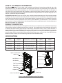
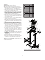
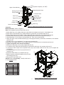
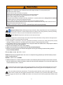
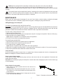
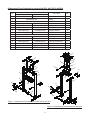
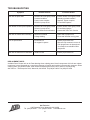
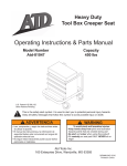
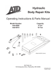
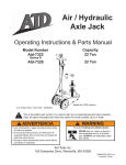
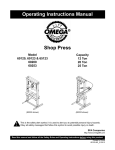
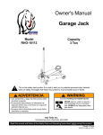
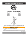
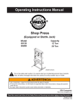
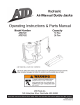
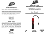
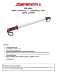
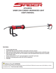
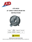
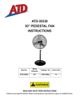
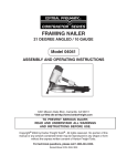
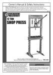
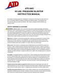
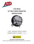
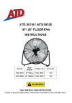
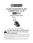
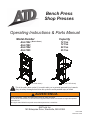
Bench Press
Shop Presses
Operating Instructions & Parts Manual
Model Number
Atd-7452
Atd-7453
Atd-7454
Atd-7455
(Bench Press)
(Atd-7454 shown)
!
Capacity
12 Ton
12 Ton
20 Ton
25 Ton
(Atd-7455 shown)
This is the safety alert symbol. It is used to alert you to potential personal injury hazards.
Obey all safety messages that follow this symbol to avoid possible injury or death.
! advertencia
• Leer, comprender, y seguir las instrucciónes antes de utilizar el aparato.
• El manual de instrucciónes y la información de seguridad deben estar comunicado en lengua del operador
antes del uso.
• No seguir estas indicaciónes puede causar daños personales o materiales.
Atd Tools Inc.
160 Enterprise Drive, Wentzville, MO 63385
7452-1209
Printed in China
SAFETY and GENERAL INFORMATION
Save these instructions. For your safety, read, understand, and follow the information provided with and on this
product before using. The owner and operator of this equipment shall have an understanding of this product and
safe operating procedures before attempting to use. The owner and operator shall be aware that use and repair of
this product may require special skills and knowledge. Instructions and safety information shall be conveyed in the
operator's native language before use of this jack is authorized. If any doubt exists as to the safe and proper use of
this jack, remove from service immediately.
Inspect before each use. Do not use if broken, bent, cracked or damaged parts are noted. Any press that appears
damaged in any way, or operates abnormally shall be removed from service immediately. If any component of this
product has been subjected to a shock load (a load dropped suddenly, unexpectedly upon it), immediately discontinue
use until checked by a factory authorized service center (contact distributor or manufacturer for list of authorized
service centers). It is recommended that an annual inspection be done by qualified personnel. Labels and Operator's
Manuals are available from manufacturer.
PRODUCT DESCRIPTION
Atd Tools Bench Press & Shop Press are designed for automotive, truck, implement, fleet, and industrial repair shops
where pressing, bending, straightening and forming, is required. Typical applications include installation and removal
of alternator and power steering pump bearings, axle bearings, transmission bearings, seals, u-joints and others. It
is not intended for use as an assembly table or as fixture stand used to secure a large, final assembly component.
Unlike presses equipped with a separately mounted pump, the power unit on this press can not be equipped with a
pressure gauge, therefore monitoring the load must be done by other means, such as a load cell w/ digital indicator.
Whatever means is chosen, the load measuring means shall be calibrated annually.
SPECIFICATIONS
Model
Capacity
Press Size ( L X W X H )
Max. Working
Space
Min. Working
Space
Atd-7452
12 Ton
22-3/4" x 18-1/2" x 38"
14-1/4"
2-3/8"
Atd-7453
12 Ton
22-3/4" x 18-1/2" x 59"
34-3/8"
2-5/8"
Atd-7454
20 Ton
28" x 28" x 64-1/2"
34-1/8"
2-1/2"
Atd-7455
25 Ton
28" x 28" x 59"
34-1/4"
2-1/2"
Saddle
Upper Cross Member
Ram
Bottle Jack
Oil Filler Plug
Jack Bracket
Handle Sleeve
Jack Handle
Bed Frame
Release Valve
Support Pin
Bottle Jack
Arbor Plate
Upright Channel
Support Link
Lower Cross Member
Base Leg
Figure 1 - Shop Press Components (Atd-7454 shown)
2
PREPARATION
Before Use
1. Verify that the product and application are compatible, if in doubt call Atd Tools technical service (636) 3279050.
2. Before using this product, read the operator's manual completely and familiarize yourself thoroughly with the
product, its components and recognize the hazards associated with its use.
3. To familiarize yourself with basic operation of bottle jack (use the notched or stamped end of provided handle to
engage) or hand pump and turn the release valve:
a. Clockwise until firm resistance is felt to further turning. This is the ‘CLOSED’ release valve position used to
extend the ram.
b. Counter-clockwise, but no more than 1 full turn from the closed position. This is the ‘OPEN’ release valve
position used to retract the ram.
4. With ram fully retracted, remove the oil filler plug. Insert the handle into the handle sleeve, then pump 6 to 8
strokes. This will help release any pressurized air, which may be trapped within the reservoir. Ensure the oil level
is just below the oil filler hole. Reinstall the oil filler plug.
5. For model Atd-7455: withith release valve opened, remove the oil filler screw. Ensure the oil level is within 1/4"
(6mm) of the opening. Reinstall the oil filler screw.
6. Check that the pump operates smoothly and that the extension screw will thread up/down easily before putting
into service. Replace worn or damaged parts and assemblies with Atd Tools authorized replacement parts only.
Bleeding / Venting Trapped Air
With the release valve in the OPEN position (3b above) and with ram fully lowered, remove the oil filler plug. Insert
handle into the handle sleeve; then pump 6 to 8 full strokes. This will help release any pressurized air which may be
trapped within the reservoir. Oil level should be even with the bottom of the oil filler hole. Reinstall the oil filler plug.
Assembly
Model Atd-7453: (Refer to Figure 2)
NOTICE: Before disassembly, carefully slide bed to its
fully lowered position.
Note: Do not tighten any bolts unless told to do so.
1. Attach base legs (1) and lower cross member (4) to
upright channels (2) with bolts, flat washers, lock
washers and nuts (3). Hand tighten only.
2. Attach support links (5) to the base (1) and upright
channels (2) with bolts, flat washers, lock washers
and nuts (3).
3. Carefully slide bed frame (6) down to lowest possible
position between the upright channels (2).
4. Attach screw hooks (7) to the jack bracket (8) with
nuts (9) as shown in figure 2. Leave nut untighten
to provide easy spring attachment.
5. Slide the jack bracket (8) down between upright
channels (2) onto the bed frame (6).
6. Attach upper cross member (10) to upright channels (2)
with bolts, flat washers, lock washers and nuts (11).
7. Attach one end of the springs (15) to the axles of
upper cross member (10) and the other end to the
screw hooks (7) on the jack bracket.
8. Carefully place the bottle jack (16) between the head
plate of upper cross member (10) and jack bracket
(8). Tighten the nuts (9) that hold screw hooks (7) to
prevent jack from inadvertently falling out.
9. Tighten all applicable nut and bolt assemblies.
10. Carefully bring the bed frame (6) up and secure it
with pins (9).
11. Place the Arbor Plates (17) on Bed Frame (6).
12.The press is now ready to use. Don’t forget to insert
the handle (18) into handle sleeve of bottle jack.
Size of Hardware Kits
Qty Size of Hardware Kits
Qty
3 bolt
M10x25 8 11 bolt
M16x120 4
flat washer M16
8
flat washer M10
8
lock washer M16
4
lock washer M10
8
nut
M16
4
nut
M10
8
9 nut
M8
4
10
11
16
15
7
9
18
8
17
19
3
5
6
1
3
4
2
Figure 2 - Assembly Illustration for model Atd-7453
Assembly
Model Atd-7454: (Refer to Figure 3)
Size of Hardware Kits
3 bolt
M10x25
lock washer
M10
nut
M10
9 nut
M8
11 bolt
M16x150
flat washer
M16
lock washer
M16
nut
M16
13 bolt
M10x25
lock washer
M10
square washer M10
14 bolt
M10x130
lock washer
M10
nut
M10
Note: Do not tighten any bolts unless told to do so.
1. Attach base legs (1) to upright channels (2) with bolts,
lock washers and nuts (3). Hand tighten only.
2. Attach lower cross member (4) to upright channels
(2) with bolts, lock washers and nuts (3).
3. Attach support links (5) to the base (1) and upright
channels (2) with bolts, lock washers and nuts (3).
4. Carefully slide bed frame (6) down to lowest possible
position between the upright channels (2).
5. Attach the screw hooks (7) to the jack bracket (8)
with nuts (9). Leave nut untighten to provide easier
spring attachment later.
6. Slide the jack bracket (8) down between upright
channels (2) onto the bed frame (6).
7. Attach upper cross members (10) to upright channels
(2) with bolts, flat washers, lock washers and nuts
(11).
8. Attach head plate (12) to upper cross members (10)
with bolts, lock washers and square washers (13).
9. Attach two bolts, lock washers and nuts (14) thru the
upper cross member (10). Then attach one end of
the springs (15) to the bolts (14) and the other end
to the screw hooks (7) on the jack bracket.
10. Carefully place the bottle jack (16) between the
head plate (12) and jack bracket (8). Tighten the
nuts (9) that hold screw hooks (7) to prevent jack
from inadvertently falling out.
11 . T i g h t e n a l l a p p l i c a b l e n u t s a n d b o l t
assemblies.
12. Carefully bring the bed frame (6) up and secure it
with pins (19).
13. Place the Arbor Plates (17) on Bed Frame (6).
14.The press is now ready to use. Don’t forget to insert
the handle (18) into handle sleeve of bottle jack
Qty
12
12
12
2
4
8
4
4
4
4
4
2
2
2
10
14
13
12
15
16
7
18
8
9
17
6
11
19
NOTICE: Before disassembly, carefully slide bed to
its fully lowered position.
2
1
4
5
3
3
Figure 3 - Assembly Illustration for model Atd-7454
4
Ram
Hydraulic Couplers (1/4" NPT)
Upper Cross Member
Hydraulic Hose
Bearing Punch
Pump Handle
Release Valve
Hand Pump
Oil Filler Screw
Pump Bracket
Bed Frame
Support Pin
Arbor Plate
Support Link
Upright Channel
Base Leg
Lower Cross Member
Assembly
Models Atd-7455: (Refer to Figure 5)
Figure 4 - Shop Press Components (Atd-7455 shown)
Note: Do not tighten any bolts unless told to do so.
1. Attach base legs (1) to upright channels (2) with bolts, lock washers and nuts (3). Hand tighten only.
2. Attach lower cross member (4) to upright channels (2) with bolts, lock washers and nuts (3).
3. Attach support links (5) to the base (1) and upright channels (2) with bolts, lock washers and nuts (3).
4. Carefully slide bed frame (6) down to lowest possible position between the upright channels (2).
5. Slide head plate (7) to into upper cross members (8). Then, secure with bolts (9).
6. Attach the upper cross members assembly (8) to the upright channels (2) with bolts, flat washers, lock washers
and nuts (10).
7. Thread the ram (11) to head plate (7) on upper cross members (8).
8. Attached pump support bracket (12) to upright channel (2) with three bolts, lock washers and nuts (3).
9. Tighten all aplicable nuts and bolt assemblies.
10. Place the hand pump (13) on pump support bracket (12).
11. To hold the pump, attach the fixed backets (14) and secure with bolts, lock washers and nuts (3).
12. Connect the male coupler end of hydraulic hose (15) to the female coupler of the ram (11) to complete the
connections.
8
13. Carefully bring the bed frame (6) up and secure it
11
with pins (16).
10
15
14. Place the Arbor Plates (17) on Bed Frame (6).
15 When necessary, replace the saddle of ram (11) with
9
the bearing punch (18).
18
7
16.The press is now ready to use.
17
NOTICE: Before disassembly, carefully slide bed to
13
its fully lowered position.
16
3
Size of Hardware Kits
3 bolt
M10x25
lock washer M10
nut
M10
9 bolt
10x25
10 bolt
M16x150
flat washer M16
lock washer M16
nut
M16
Qty
19
19
19
2
4
8
4
4
6
14
3
3
2
12
1
4
3
5
5
Figure 5 - Assembly Illustration for model Atd-7455
! WARNING
• Study, understand, and follow all printed materials provided with/on this product before use.
• Always use an adequately rated, calibrated load cell with digital indicator to monitor pressing force!
• Do not exceed rated capacity.
• Use the device only on a hard, level surface.
• Always wear safety goggles when working on or near this equipment.
• Keep hands, feet and all other body parts away from loading area.
• Never leave loaded press unattended.
• Projectile hazard! Ensure workpiece and any attachment is centrally loaded and a safety shield is installed
around workpiece to help protect against projectiles.
• Do not modify this device beyond installing a shield to protect against projectiles.
• Ensure the user is familiar with the controls and operational characteristics of this product and aware of the
potential hazards associated with its use.
• Failure to heed these markings may result in personal injury and/or property damage.
OPERATION
Projectile Hazard! Wear ANSI approved eye protection. Never stand directly in front of loaded press.
Ensure that workpiece is center-loaded and secure. Reduce risk of flying debris by carefully following
all operating instructions. Know your press and hazards associated with its use.
!
Crush Hazard! Keep hands and feet from bed area at all times.
1. Insert the support pins to desired height, then lower the bed. Ensure bed frame is fully rested on the support pins.
2. Place arbor plates on the bed frame as needed.
3. Place workpiece on bed frame, using every precaution necessary to ensure your safety and prevent property
damage. Position workpiece in a manner which will not allow it to inadvertently fall from bed.
4. Close release valve by turning it clockwise firmly, insert jack handle into handle sleeve, and pump the handle to
extend the ram until ram nears workpiece.
5. Align ram and workpiece to ensure center-loading.
6. Apply load to workpiece by pumping handle. Do not overload workpiece
7. Monitor the pressure gauge and calcualte the applied load using the following formula as basic guideline:
Force = Pressure X Area
Effective Area of model Atd-7455 = 5.14 in²
Problem: Determine the applied load in lbs. force on a workpeice being pressed by a Atd-7455 whose pressure
gauge is reading 2200 psi.
Solution: 2200 X 5.14= 11,308 lbs
8. Stabilize workpiece in a manner which will not allow it to inadvertently fall from the bed once the load is removed,
then turn release valve counter-clockwise to retract the ram and remove workpiece. Do not turn the release valve
counter-clockwise more a 1 full turn.
!
To reduce the risk of personal injury and/or property damage, ensure that the rated working pressure of each
pressurized attachment be equal to or greater than the rated working pressure developed by the pump.
Use only handle provided by manufacturer. The handle provided with this product will safely engage the
release valve of bottle jack and operate the handle sleeve. If handle is worn, operates abnormally, or will not
positively engage the release valve, STOP, discontinue use of the jack until a factory replacement handle can be
acquired.
!
6
Unlike presses equipped with a separately mounted pump, the power unit on this press can not
be equipped with a pressure gauge, therefore monitoring the load must be done by other means,
such as a load cell w/ digital indicator. Whatever means is chosen, the load measuring means shall be calibrated
annually.
!
The hydraulic power unit provided with this device is intended to be used as an integral part of this press and
not as a stand-alone jacking device separate of the press. Never use the hydraulic power unit provided with
this press for any purpose other than that for which it is intended.
!
MAINTENANCE
Before each use, inspect press for damage. Do not use if bent, broken, cracked, leaking or otherwise damaged
components are noted. Periodically, lightly oil all moving parts, including the pump piston and ram.
Adding/Changing oil to bottle jack
For Bottle Jack models Atd-7452, Atd-7453 & Atd-7454:
Important: Use only good grade hydraulic jack oil. Avoid mixing different types of fluid and NEVER use brake fluid,
turbine oil, transmission fluid, motor oil or glycerin. Improper fluid can cause premature failure of the jack and the
potential for sudden and immediate loss of load. Mobil DTE 13M or equivalent recommended.
For best results, change fluid once a year.
1. Remove jack from press frame.
2. With ram fully lowered and pump piston fully depressed, set jack in its upright, level position. Remove oil filler plug.
3. Drain used fluid into a suitable container
Note: Dispose of hydraulic oil in accordance with local regulations.
4. Fill until oil is level with or just below filler plug hole.
For hand Pump model Atd-7455:
1. Depressurize and disconnect hydraulic hose from application.
2. Remove oil filler screw located on top of the reservoir.
3. Pour used fluid into a sealable container.
Note: Dispose of hydraulic fluid in accordance with local regulations.
4. With pump in its upright, horizontal position, use a small funnel to fill reservoir to within 1/4” (6 mm) of the opening.
5. Wipe up any spilled fluid and reinstall the vented oil filler screw.
Rust prevention
Check ram and pump piston for signs of rust on a regular basis. Clean as needed with a lint free, oil saturated cloth.
Never use sandpaper or abrasive material on these surface.
How to remove faulty coupler:
If ram does not retract: Depressurize pump and hose, then remove the ram from application. Disconnect and
replace with new coupler.
Important: Do not attempt to grasp ram with pliers or wrench without first wrapping the jaws of such tool with rags
or similar padding.
How to bleed air from system:
1. Place pump at a higher elevation than the hose and ram as
shown in figure 4.
2. Operate pump to fully extend and retract the ram 2 or 3 times.
The objective is to force the air bubbles up hill and back to the
pump reservoir.
3. To bleed the air from pump reservoir, simply open the oil filler
screw. Re-install after bleeding.
7
Figure 6 - Illustration to bleed air from system
Replacement Parts illustration for models Atd-7452, Atd-7453 & Atd7454
Item
1
2
3
4
5
6
7
8
9
10
11
12
13
14
-
Part# for model:
Atd-7452 & Atd-7453
Atd-7454
T060-05000-000
T126-00003-000
T060-00001-100
T060-00002-100
B120-10000-000
B200-10000-000
T060-04000-000
T126-02000-000
B080-20000-000
T126-03000-000
T060-00003-100
T126-00001-000
T060-02000-000
T125-01000-000
T184-00004-000
T060-00006-000
T184-00005-000
T060-03000-000
T125-02000-000
T060-01000-100
T184-00006-000
T184-00007-000
T125-00007-000
T126-01000-000
T060-06000-000
T126-04000-000
Description
Qty
Upper Cross Member
Spring
Screw Hook
Bottle Jack
Jack Bracket
Jack Handle
Upright Channel
Support Pin
Support Link
Base Leg
Bead Frame
Lower Cross Member
Arbor Plates (pair)
Head Plate
Hardware Kit
1
2
2
1
1
1
2
2
2
2
1
1
1
1
1
1
14
4
2
4
3
6
2
5
13
3
6
5
7
11
8
7
13
9
8
11
9
10
12
10
12
Figure 7 - Replacement Parts Illustration for Atd-7452 & Atd-7453
Figure 8 - Replacement Parts Illustration for Atd-7454
8
Replacement Parts illustration for model Atd-7455
Item
Part# for model:
1
2
3
4
5
6
7
8
9
10
11
12
13
14
15
T125-00001-000
T125-00003-000
T125-00007-000
T125-02000-000
T125-01000-000
T125-00002-000
T184-00006-000
T184-00004-000
T184-00005-000
T184-00003-000
F100-90004-K01
T125-00008-000
F040-90107-K02
T125-03000-000
F250-30000-000
F040-90009-K04
F040-90009-K05
F100-90009-K01
55255
T125-04000-000
16
17
-
Description
Qty
Upper Cross Member
Punch
Arbor Plates (pair)
Bed Frame
Support Pin
Upright Channel
Lower Cross Member
Support Link
Base Leg
Pump Bracket
Hand Pump
Fixed Bracket
Oil Filler Screw
Head Plate
Ram
Coupler, Female 1/4" NPT
Coupler, Male 1/4" NPT
Pump Handle
Pump & Ram Assembly (#11 & 15)
Hardware Kit
2
1
1
1
2
2
1
2
2
1
1
2
1
1
1
1
1
1
15
1
16
2
14
3
17
5
6
13
4
12
11
10
9
7
8
Figure 9 - Parts Illustration for Atd-7455
9
TROUBLESHOOTING
Symptom
Possible Causes
Corrective Action
• Release valve not tightly closed
• Overload condition
• Faulty/ Loose couplers
• Oil lever in pump is low
• Ensure release valve tightly closed
• Remedy overload condition
• Replace/ Tighten couplers
• Fill and bleed system
Ram bleeds off after press operation • Release valve not tightly closed
• Oil lever in pump is low
• Ram or Bottle Jack malfunction
• Ensure release valve tightly closed
• Fill and bleed system
• Contact Atd Tools Tech. Service
Ram will not retract after unloading
• Reservoir overfilled
• Linkage binding
• Drain fluid to proper level
• Clean and lubricate moving parts
Poor lift performance
• Fluid level low
• Air trapped in system
• Ensure proper fluid level
• With ram fully retracted, remove oil
filler plug/screw to let pressurized
air escape, then reinstall oil filler
plug/screw
Ram will not extend to full extension
• Fluid level low
• Ensure proper fluid level
Ram will not press load
REPLACEMENT PARTS
Available Parts: Please refer to the Parts drawing when ordering parts. Not all components of this kit are replacement items, but are illustrated as a convenient reference of location and position in the assembly sequence. When
ordering parts, give Model number, serial number and description below. Call or write for current pricing:
Atd Tools Inc. 160 Enterprise Drive, Wentzville, MO 63385 Tel:(636)327-9050 Fax:(636)327-9046
Atd Tools Inc.
160 Enterprise Drive, Wentzville, MO 63385
Tel: (636)327-9050 Fax: (636)327-9046 www.atdtools.com
10
ONE YEAR LIMITED WARRANTY
For a period of one (1) year from date of purchase, Atd Tools Inc. will repair or replace, at its option, without charge,
any of its products which fails due to a defect in material or workmanship, or which fails to conform to any implied
warranty not excluded hereby.
Performance of any obligation under this warranty may be obtained by returning the warranted product, freight
prepaid, to Atd Tools Inc. Warranty Service Department, 160 Enterprise Drive, Wentzville, MO 63385.
Except where such limitations and exclusions are specifically prohibited by applicable law, (1) the CONSUMER'S
SOLE AND EXCLUSIVE REMEDY SHALL BE THE REPAIR OR REPLACEMENT OF DEFECTIVE PRODUCTS AS
DESCRIBED ABOVE, and (2) Atd Tools Inc. SHALL NOT BE LIABLE FOR ANY CONSEQUENTIAL OR INCIDENTAL DAMAGE OR LOSS WHATSOEVER, and (3) THE DURATION OF ANY AND ALL EXPRESSED AND IMPLIED
WARRANTIES, INCLUDING WITHOUT LIMITATION, ANY WARRANTIES OF MERCHANTABILITY AND FITNESS
FOR A PARTICULAR PURPOSE, IS LIMITED TO A PERIOD OF ONE (1) YEAR FROM DATE OF PURCHASE.
Some states do not allow limitations on how long an implied warranty lasts, so the above limitation may not apply
to you. Some states do not allow the exclusion or limitation of incidental or consequential damages, so the above
limitation or exclusion may not apply to you. This warranty gives you specific legal rights, and you may also have
other rights which vary from state to state.
Atd Tools Inc.
160 Enterprise Drive, Wentzville, MO 63385
Tel: (636)327-9050 Fax: (636)327-9046 www.atdtools.com
Notes
Atd Tools Inc.
160 Enterprise Drive, Wentzville, MO 63385
Tel: (636)327-9050 Fax: (636)327-9046 www.atdtools.com