1
Customer Care available 24 hours a day,
7 days a week at: 1-866-597-5520
www.continuousmonitor.com
User’s Guide
This product and its use are protected under U.S. Patent Numbers:
5,262,035; 5,264,104; 5,264,105; 5,593,852; 5,899,855; 5,918,603; 5,965,380; 6,071,391; 6,103,033;
6,120,676; 6,121,009; 6,134,461; 6,143,164; 6,162,611; 6,175,752; 6,284,478; 6,299,757; 6,329,161;
6,338,790; 6,461,496; 6,484,046; 6,503,381; 6,514,718; 6,560,471; 6,565,509; 6,591,125; 6,592,745;
6,605,200; 6,605,201; 6,616,819; 6,618,934; 6,676,816; 6,749,740; 6,893,545; 6,932,894; 6,942,518;
6,973,706; 6,990,366; 7,003,340; 7,003,341; 7,074,308; 7,090,756; 7,299,082.
Abbott Diabetes Care Inc., 1360 South Loop Road, Alameda, CA 94502 ©2008 Abbott
ART16072 Rev. A 05/08
CAUTION: Federal law restricts this device to sale by or on the order of a physician.
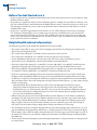
Indications for Use
The FreeStyle Navigator® Continuous Glucose Monitoring System is indicated for continually
recording interstitial fluid glucose levels in people (ages 18 and older) with diabetes mellitus
for the purpose of improving diabetes management. Readings and alarms about glucose
levels from FreeStyle Navigator® Continuous Glucose Monitoring System are not intended
to replace traditional blood glucose monitoring. Before adjusting therapy for diabetes
management based on the results and alarms from the FreeStyle Navigator® Continuous
Glucose Monitoring System, traditional blood glucose tests must be performed. The FreeStyle
Navigator® Continuous Glucose Monitoring System provides a built-in blood glucose meter to
confirm the continuous glucose result.
The FreeStyle Navigator® Continuous Glucose Monitoring System provides real-time readings,
graphs, trends, and glucose alarms directly to the user. The FreeStyle Navigator® Continuous
Glucose Monitoring System is intended to be used in home settings to aid people with
diabetes in predicting and detecting episodes of hypoglycemia and hyperglycemia and in
clinical settings to aid health care professionals in evaluating glucose control. The FreeStyle
Navigator® Continuous Glucose Monitoring System is available only by prescription.
Contraindications
The FreeStyle Navigator® Continuous Glucose Monitoring System must be removed prior to
Magnetic Resonance Imaging (MRI).
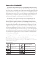
How to Use this Guide?
This guide has many Sections arranged in a logical sequence that will be useful
for the first time use and every use thereafter. Most Sections begin with a purpose for
that Section, when to perform the steps in that Section, materials required to perform
the steps in that Section and important cautions, warnings and helpful information.
The first page of each Section will be very useful when you are getting familiar with
the system. Once you are familiar with the system and the typical precautions, you
may find yourself relying less on the first page of the individual Sections.
The remainder of each Section describes the steps to perform the tasks. The
steps are organized in a simple manner to allow you to see what to do based on
what you experience and based on where you are in that particular Section. It is
important that you go through the steps in the order that they have been presented.
Every Section also indicates if you have reached the end of the Section. If you find
it difficult to use the guide or if you seem lost or confused, use the table of contents,
index, glossary and appendices to help you. The table of contents provides a list of
Sections you will find in this guide and what each Section contains. The appendices
have useful information that you may want to refer to. The glossary provides a list of
terms and what they mean. The index is a tool you could use to quickly find terms
and items that you are looking for.
• FreeStyle Navigator® and FreeStyle® are registered trademarks of the Abbott Group of Companies
in various jurisdictions.
• OpSite® IV 3000 and Uni-Solve® are trademarks of Smith and Nephew Inc.
• Bluetooth® wireless technology is a trademark of the Bluetooth SIG Inc.
• YSI 2300 STAT Plus™ Glucose Analyzer is a trademark of Yellow Springs Instrument Inc.
• Energizer® Max®, Energizer® e2® Titanium® and Energizer® Industrial Batteries are trademarks of
the Eveready Battery Company Inc.
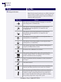
Glossary of Symbols
Do not re-use
Temperature limitation
Rx only. For use by
prescription only
Manufactured by
Sterile
Consult operating instructions
Use by
Batch code
Serial number
Catalog number
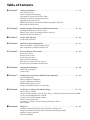
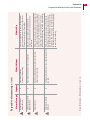
Table of Contents
n Section 1:
Getting Acquainted. . . . . . . . . . . . . . . . . . . . . . . . . . . . . . . . . . . . . . . . . . . . . . . . . . . . 1 – 12
Parts of the System.
Daily Activities and Traveling.
Preparing the System for the First Time.
Warnings, Cautions and Important Notes.
Hypoglycemia Unawareness.
Modes of Operation (Continuous Monitoring Mode (CM) and
Blood Glucose Mode (BG)).
n Section 2:
Install or Replace Transmitter and Receiver Batteries . . . . . . . . . . . . . . . . . . . . . . 15 – 18
Installing the Batteries in Your System.
Battery Types for the Transmitter and the Receiver.
When to Change the Batteries?
n Section 3:
Set the Time and Date . . . . . . . . . . . . . . . . . . . . . . . . . . . . . . . . . . . . . . . . . . . . . . . . . 21 – 23
Set the Time and Date.
n Section 4:
Perform a Control Solution Test. . . . . . . . . . . . . . . . . . . . . . . . . . . . . . . . . . . . . . . . 27 – 31
When to Perform a Control Solution Test?
How to Perform a Control Solution Test?
n Section 5:
Insert or Remove Your Sensor. . . . . . . . . . . . . . . . . . . . . . . . . . . . . . . . . . . . . . . . . . 35 – 43
Insert Your Sensor.
Remove Your Sensor.
Sensor Insertion Sites.
Prepare the Insertion Site.
How Long Can You Wear the Sensor?
Reconnect the Transmitter and Receiver.
n Section 6:
Attach your Transmitter. . . . . . . . . . . . . . . . . . . . . . . . . . . . . . . . . . . . . . . . . . . . . . . 47 – 50
Attach the Transmitter.
Sensor Code.
n Section 7:
Calibrate your System/Test Blood Glucose Manually. . . . . . . . . . . . . . . . . . . . . . . 53 – 63
System Calibration.
Time to Perform Calibration.
Sample Calibration Schedules.
Perform Blood Glucose Tests.
Interpret Your Blood Glucose Test Results.
n Section 8:
Set, Review, or Change the Alarm Settings . . . . . . . . . . . . . . . . . . . . . . . . . . . . . . . 67 – 78
About Glucose Alarms.
Choose Alarms Settings: On/Off, Type (beep vs. vibrate) and Glucose Alarm Threshold.
Set the Low and High Glucose Alarms.
Set Projected (Early Warning) Alarms.
What is Alarm Sensitivity?
Set Data Loss Alarms, System Alarms, and Progress Tones.
Mute Alarms.
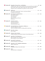
n Section 9:
Daily Use. . . . . . . . . . . . . . . . . . . . . . . . . . . . . . . . . . . . . . . . . . . . . . . . . . . . . . . . . . . . 81 – 85
Maintain Connection Between the Transmitter and Receiver.
Interpret the Glucose Results in the Continuous Monitoring Mode.
Symbols, Arrows and Icons.
Receiver Backlight.
n Section 10: Respond to Alarms, Errors, and Problems. . . . . . . . . . . . . . . . . . . . . . . . . . . . . . . 89 – 108
Alarm Messages: What are they, What do they mean, and What you should do.
Error Codes: What are they, What do they mean, and What you should do.
Problems: How to troubleshoot the problems you may encounter.
n Section 11: Add Events . . . . . . . . . . . . . . . . . . . . . . . . . . . . . . . . . . . . . . . . . . . . . . . . . . . . . . . . 111 – 114
Enter Events: Insulin, Meals, Exercise, and State of Health.
Customize Generic Events.
n Section 12: Review Reports and Edit Events . . . . . . . . . . . . . . . . . . . . . . . . . . . . . . . . . . . . . . 117 – 124
Enter Glucose Targets.
View Line Graph.
View Statistics.
Review the History of Events.
Edit Events.
n Section 13: Clean Your System . . . . . . . . . . . . . . . . . . . . . . . . . . . . . . . . . . . . . . . . . . . . . . . . . 127 – 128
Clean Your Transmitter.
Clean Your Receiver.
Clean Your Receiver Skin.
n Section 14: Link and Unlink your Transmitter and Receiver. . . . . . . . . . . . . . . . . . . . . . . . 131 – 133
Link and Unlink your System.
What is the Difference Between Linking and Reconnecting?
n Section 15: Reset User Settings . . . . . . . . . . . . . . . . . . . . . . . . . . . . . . . . . . . . . . . . . . . . . . . . . 137 – 138
Reset Settings.
n Section 16: Change Country Settings . . . . . . . . . . . . . . . . . . . . . . . . . . . . . . . . . . . . . . . . . . . . 141 – 144
Change Language, Date and Time Formats, Decimal Point format.
n Section 17: Appendix A: Site Maintenance . . . . . . . . . . . . . . . . . . . . . . . . . . . . . . . . . . . . . . . . . . . . . 147
How to Maintain the Sensor Insertion Site?
How to Improve Sensor Adhesion?
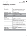
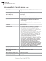
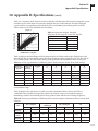
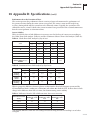
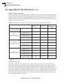
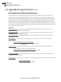
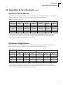
n Section 18: Appendix B: Specifications . . . . . . . . . . . . . . . . . . . . . . . . . . . . . . . . . . . . . . . . . . 151 – 162
System Performance Specifications.
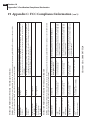
n Section 19: Appendix C: FCC Compliance Information . . . . . . . . . . . . . . . . . . . . . . . . . . . . 165 – 171
Wireless Interference.
n Section 20: Glossary . . . . . . . . . . . . . . . . . . . . . . . . . . . . . . . . . . . . . . . . . . . . . . . . . . . . . . . . . . 175 – 180
Definitions of Terms Used in This Guide.
n Section 21: Index. . . . . . . . . . . . . . . . . . . . . . . . . . . . . . . . . . . . . . . . . . . . . . . . . . . . . . . . . . . . . 183 – 184
Find What You are Looking For.
1 Getting Acquainted
Section 1 – Key Terms
n
n
n
Alarms
Blood Glucose Mode
Continuous Monitoring Mode
FreeStyle Navigator Continuous Glucose
Monitoring System
n
n
n
in vitro
n
Interstitial Fluid
n
Left/Right Option Buttons
n
Receiver
n
Receiver Display Screen
n
Receiver Test Strip Port
n
Reports
n
Sensor
n
Sensor Delivery Unit
n
Sensor Inserter
n
Sensor Insertion Button
n
Sensor Locking Pin
n
Sensor Release Tabs
n
Sensor Support Mount
n
Transmitter
n
Transmitter Tabs
n
Up/Down Arrow Buttons
FreeStyle Test Strips
Customer Care: 1-866-597-5520
1
Section 1 1
Getting Acquainted
1 Getting Acquainted
Introduction
Important: Read all of the instructions in this User’s Guide and the FreeStyle® Test Strip package
insert before using your FreeStyle Navigator® Continuous Glucose Monitoring System. Adjustments to
your treatment should be done under the guidance of your healthcare team.
Your FreeStyle Navigator system continuously reads, displays, and records the glucose levels in the
fluids found between the cells under your skin (interstitial fluids). It does this by using a small, thin,
plastic sensor inserted just under the skin.
Your FreeStyle Navigator system provides you with continuous glucose readings in real time. By
having access to more frequent glucose measurements, you can monitor your glucose levels and gain
an understanding of patterns in your glucose levels. This will help you and your healthcare team see
how factors such as your diet, insulin, exercise, and diabetes medication affect your glucose levels,
and to adjust your treatment plan accordingly.
Your FreeStyle Navigator system has a number of helpful features.
• Wireless communication between the transmitter and receiver.
• Disposable sensor that can be worn up to 5 days.
• Alarms to alert you to low or high glucose levels (hypoglycemia or hyperglycemia) before
reaching those low and high glucose levels and when reaching those glucose levels.
• Graphs and statistics that show your glucose results in easy-to-understand formats.
• Directional glucose trend arrows that show if your glucose values are rising or falling and
how fast.
• Memory to hold up to 60 days worth of data.
• Wireless communication capabilities to a personal computer.
• Built-in FreeStyle® Blood Glucose Meter for performing blood glucose measurements.
• Event entry capabilities (like meals, exercise, insulin and other).
• Backlit display.
Important: Keep this User’s Guide for future reference. It will come in handy when you have to do
procedures that you do not do often enough to remember.
OVER
2 Section 1
Getting Acquainted
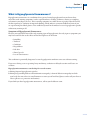
How are the parts packaged?
Your FreeStyle Navigator system comes with two kits:
• A System kit.
• A Sensor kit.
The System Kit
•
•
•
•
•
•
•
•
•
•
•
•
•
•
•
•
•
1 FreeStyle Navigator Receiver in a Receiver Skin
2 AAA Alkaline Batteries (for the receiver)
1 FreeStyle Navigator Transmitter
1 Silver Oxide 357 HC Battery (for the transmitter)
1 Belt Clip (for the receiver)
1 FreeStyle Lancing Device
The Sensor Kit
1 Finger Cap (for the lancing device)
ntaining
Delivery Units (each co
• 6 Sterile Sensor
1 User’s Guide
ert
a sensor) and Product Ins
1 Getting Started Guide
placement Battery (for
1 Silver Oxide 357 HC Re
•
1 Quick Reference Card
the transmitter)
1 Welcome Card
6 Overbandages
12 Alcohol Prep Pads
30 Sterile Lancets
1 Vial of FreeStyle Control Solution and Insert
1 Vial of 50 FreeStyle Strips and Strip Insert
1 Warranty Registration Card
• In addition, the FreeStyle Navigator system can transfer data to a computer wirelessly using
Bluetooth® technology.
Important Notes:
• The FreeStyle Navigator® Continuous Glucose Monitoring System is designed as a complete
system. Use only the FreeStyle Navigator Sensor, the FreeStyle Navigator Transmitter, the
FreeStyle Navigator Receiver and FreeStyle Test Strips.
• The system is intended for your personal use; do NOT share your system with others.
Customer Care: 1-866-597-5520
Section 1 3
Getting Acquainted
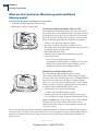
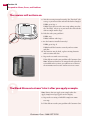
What are the key parts of my system?
Your FreeStyle Navigator system includes the following major parts:
Sensor
Measures your glucose level.
Sensor Tip
Part of sensor inserted into your skin.
Locking Pin
Prevents accidental discharge;
must be removed before insertion.
Insertion Button
Pushes a tiny needle into the
skin to place the sensor tip just
under the surface of the skin.
Sensor Inserter
Inserts the sensor into
the skin. Must be disposed
after inserting the sensor.
Sensor Support Mount
Stays on your skin after sensor is inserted.
Holds the sensor in place. Attaches the
sensor to the transmitter.
Sensor
Delivery
Unit
Release Tabs
Releases the sensor inserter
from the sensor support mount.
Adhesive Protective Liner
Adhesive that is affixed to your skin.
Transmitter
Tabs
Guides
Display Screen
Displays glucose levels
and other information.
Test Strip Port
Where FreeStyle Test
Strips are inserted to
calibrate the receiver
or manually check
blood glucose levels.
Receiver in Receiver Skin
Receiver
UP and DOWN Arrow Buttons
Used to move through lists to highlight
options and change numbers.
LEFT and RIGHT Option Buttons
Used to select options shown on the
screen. The RIGHT Option button also
turns the receiver on.
a.A FreeStyle Navigator Sensor that you insert about 5 mm under your skin. Each inserted sensor is
intended to remain in place and provide a continuous glucose reading for up to 5 days. The sensor is
contained in the Sensor Delivery Unit.
b.A wireless FreeStyle Navigator Transmitter (Tx), a small electronic device that connects to the sensor
and sends glucose values to the receiver once every minute.
c.A wireless FreeStyle Navigator Receiver (Rx) that captures and displays glucose measurements. With the
press of a button, the receiver displays the glucose measurement taken from the sensor.
Note: The receiver also has a built-in FreeStyle Blood Glucose Meter that can be used for blood glucose
testing. The receiver should always be kept with you on a belt, in a pocket, or in a purse.
OVER
4 Section 1
Getting Acquainted
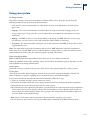
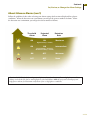
Key features of the System
Alarms
Stats 21 day
Highest CM:
Lowest CM:
Ave. CM:
Std. Dev:
Above Target:
Next
Select Event
Insulin
Meals
Exercise
State of Health
Generic
Main
08:30A
298 mg/dL
61 mg/dL
160 mg/dL
20 mg/dL
19%
Back
Statistics
08:30A
Select
Event Log
Line Graph
Your receiver comes with backlight capability to see the screen in dark environments. The backlight
can be turned on by pressing and releasing the down Arrow button and then pressing and releasing
the right Option button.
For more details on the different symbols and icons on the screen, see Section 9 on “Daily Use”.
Customer Care: 1-866-597-5520
Section 1 5
Getting Acquainted
Using your system
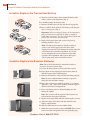
For Daily Activities
You will be wearing a sensor and a transmitter at all times while you are using the system. Keep the
following in mind as you go about your normal routine.
• Only wear the sensor and transmitter on a flat surface of either your abdomen or the back of your
upper arm.
• Sleeping – The sensor and transmitter should not interfere with your normal sleeping patterns. As
you get ready to go to sleep, place the receiver within 10 feet to maintain the transmitter-to-receiver
connection.
• Bathing – Do NOT wear the receiver while bathing or showering. Do NOT allow the receiver to get
wet. However, you can wear the sensor and transmitter while bathing or showering.
• Swimming – You may swim while wearing the sensor and transmitter. Do NOT go deeper than 1 meter
(approximately 3 feet).
Note: The connection between the transmitter and receiver is NOT maintained when the transmitter is
underwater; thus, you will NOT receive continuous glucose readings. However, when you take the sensor
and transmitter out of the water, the continuous glucose readings will resume.
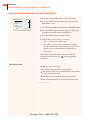
When Traveling by Plane
Note: Do NOT perform the upload data feature when you are on a commercial aircraft.
Follow the guidelines below when traveling. Always check with local authorities prior to departure as rules
and regulations may change without notice.
At the airport:
Notify the security personnel of the presence of the device when going through the security systems.
On the plane:
Check with your airline before departure whether the device will be permitted aboard the aircraft. The
airline companies set policies regarding the use of medical devices on board their flights.
If you want to disable the transmit function of the transmitter, follow these steps:
1.If you are currently wearing a sensor, remove the sensor.
2.Detach the transmitter from the sensor support mount and remove the battery from the transmitter.
3.Program into the receiver that you have ended a sensor session.
4.By removing the battery from the transmitter, you have broken the connection between the transmitter
and receiver. You can set the data loss alarms and system alarms to a short vibration mode in order to
prevent the device from sounding alarms. Once you put a new battery into the transmitter, make sure
to set the alarms to the original setting.
Note: Insert a fresh battery into the transmitter after travel before inserting a new sensor.
You can always use your receiver to check your blood glucose manually in the Blood Glucose mode.
OVER
6 Section 1
Getting Acquainted
How do I prepare my system for the first time?
When you are setting up your receiver for the first time, perform all of the procedures listed below in the
order that they are listed. Check each procedure off when you complete it.
o Install batteries in the transmitter first and then in the receiver (see Section 2).
o Set the time and date (see Section 3).
o Perform a control solution test (see Section 4).
o Insert your sensor (see Section 5).
o Attach your transmitter (see Section 6).
o Calibrate your receiver when prompted (see Section 7).
o Set the alarms in the receiver (see Section 8). Note: This can be done while waiting to perform the
first calibration.
Result: Your system is operational.
Customer Care: 1-866-597-5520
Section 1 7
Getting Acquainted
Warnings, Cautions And Important Notes
Important Notes About System Performance
The following items describe situations that could lead to inaccurate or unreliable continuous glucose
results.
Cautions:
•Movement of the sensor support mount or excessive perspiration at the sensor insertion site due to
activities like vigorous exercise or bumping against objects may lead to poor adhesion of the support
mount to the skin and cause the sensor to dislodge. If the sensor dislodges due to the sensor support
adhesive failing to adhere to the skin, you may get unreliable results or no results. The system may not
provide a warning in such circumstances. Choose the proper sensor insertion site when inserting the
sensor and prepare the site by following the instructions for site preparation.
•If your results from the Continuous Monitoring mode seem erroneous, check and make sure that the
sensor has not dislodged. If you notice the sensor is dislodged from the skin, or if you see that the adhesive
on your overbandage or the sensor support mount is coming loose, discard the old sensor and insert a
new sensor.
•The FreeStyle Navigator system includes built-in self-checks to detect conditions that may cause
the sensor to not function properly. On rare occasions the system may not be able to detect all such
conditions (for example if the adhesive peels up from your skin), and you may get inaccurate results in
the Continuous Monitoring mode. If you believe your results are not reliable, or are inconsistent with how
you feel, perform a Blood Glucose mode test to measure your glucose. If the problem continues, discard
the old sensor and insert a new sensor.
•You should never reset your user settings when you are wearing a sensor. This will reset parameters that
may affect your system performance.
•If you accept an incorrect transmitter ID when linking your Transmitter and Receiver, your glucose
readings will be incorrect.
•Do NOT use the sensor delivery unit if the sterile package is open or damaged.
Important:
•Once the code has been entered and you have hit the Set button, you will not be able to change the sensor
code number. If you have entered the code incorrectly, you will have to replace the sensor and enter the
right sensor code. If you choose the wrong sensor code, you may get erroneous results from the sensor. The
code numbers MUST match to ensure accurate test results.
•Do NOT remove or replace the transmitter from the sensor support mount while wearing a sensor. If
you notice that the transmitter is not properly attached, replace the sensor with a new sensor and then
reattach the transmitter.
Important Things to Remember About System Calibration
Caution: Always calibrate the system using only a finger-stick blood sample. Do NOT use alternate site
blood glucose measurements to calibrate the system. The receiver contains a built-in FreeStyle® Blood
Glucose Meter for performing calibration tests.
Important: Your blood glucose level must be between 60 and 300 mg/dL (3.3 and 16.7 mmol/L) to be able
to perform calibration tests. If your blood glucose level is changing rapidly, you may not be able to calibrate
the system. For example, during a meal or exercise, your glucose levels may vary rapidly. Try to time your
sensor insertion so that your calibration times do not coincide with your regular meal or exercise activities.
OVER
8 Section 1
Getting Acquainted
Important Things to Remember About System Calibration (con’t)
Important: In clinical trials, we observed that the sensor signal sometimes temporarily decreases from
the true value. This typically happens at night during sleep, and recovers rapidly when the user moves
or is awakened. However, in order to avoid being affected by this phenomenon the system should not be
calibrated when the wearer is asleep.
• You may not be able to calibrate the system if your glucose levels are changing rapidly. (e.g. during or
after exercise, meals or insulin dosing). Under such conditions, the system may not ask you to calibrate;
instead, it will delay its request until conditions are acceptable.
• You MUST successfully complete 4 calibration tests. You will calibrate at approximately 10, 12, 24 and
72 hours after sensor insertion. If you do not complete calibration tests successfully in the allotted time
periods, your glucose readings will NOT be displayed and alarms will be inactive. The system may
ask you to perform additional calibrations between 2nd and 3rd calibrations depending on the sensor
signal. In such cases, you will be prompted with a message to do additional BG tests.
• The receiver will beep (or vibrate) to prompt you to do a calibration. The receiver will display a blood
and the message “Do BG Test.” The system will prompt you with alarm messages when
drop icon
your calibrations are unsuccessful.
• You will not have continuous monitoring until you have successfully completed the first calibration (at
least for the first ten hours after sensor insertion).
• If you get a request for a calibration or expect additional calibration requests during a time when you
do not want to be disturbed (e.g. sleep time), you can choose to wait to perform additional BG tests
at a later point in time. If you choose to wait and the allotted time window for calibration has expired,
please note that you will not get glucose results until you have performed a successful calibration.
You can turn off the System Alarms (or set to vibrate) if you do not want to be disturbed by frequent
requests for calibration. In order to silence the alarms that warn you when the allotted time window for
a calibration has expired, you must turn off the data loss alarms and all the four glucose alarms (Low
Glucose, High Glucose, Projected Low Glucose and Projected High Glucose).
Before You Get Started
Installation and operation of the FreeStyle Navigator® Continuous Glucose Monitoring System requires
using a specialized introducer needle to insert the glucose sensor into the skin. Infection, inflammation,
or bleeding at the glucose sensor insertion site are possible risks of inserting a sensor into your skin.
The glucose sensor should be removed if redness, pain, tenderness, or swelling develops at the sensor
insertion site.
Cautions:
•Before adjusting treatment for diabetes management based on the continuous glucose results from your
FreeStyle Navigator system, perform a Blood Glucose mode test to confirm the continuous result.
•Performance of the FreeStyle Navigator system has not been evaluated in pregnant women.
•Performance of the system under conditions of fluctuating hydration levels such as during renal dialysis
has not been evaluated.
Customer Care: 1-866-597-5520
Section 1 9
Getting Acquainted
Before You Get Started (con’t)
Cautions:
•Low or high glucose measurements can indicate a potentially serious medical condition.
•If you have hypoglycemia, or hypoglycemia unawareness, then test ONLY on your fingers.
•The high and low alarms are intended to assist you in managing your diabetes and should not be
exclusively used to detect hypoglycemia or hyperglycemia. The alarms should always be used in
conjunction with other indications of glycemic state such as your glucose level, trend, line graph etc.
•High and low glucose alarms are DIFFERENT from your glucose targets. Low and high glucose alarms
alert you when you’ve crossed a certain low or high value. Glucose targets allow the reports and line
graphs to show how your glucose levels have been performing compared to your set targets.
•The Low Glucose alarm cannot be set below 60 mg/dL (3.3 mmol/L). Therefore, it is not intended to
notify you of severe hypoglycemia.
•The High Glucose alarm cannot be set above 300 mg/dL (16.7 mmol/L). Therefore, it is not intended to
notify you of severe hyperglycemia.
•It is important to use the correct type of batteries in the receiver, otherwise the battery life may not be
accurately monitored.
•Do NOT immerse the receiver in water or in any other liquid. Avoid getting water or any other liquid in
the test strip port.
•Changes or modifications not expressly approved by Abbott Diabetes Care, Inc. could void the user’s
authority to operate the equipment.
•The system should not be used in environments that are oxygen-rich or that contain a combustible gas.
•The radio receiver and transmitter of your FreeStyle Navigator system operate on the frequency of
433.6 MHz. Primary users of this frequency band include amateur “HAM” radio transmitters. Because
of the coexistence of the FreeStyle Navigator radio connection and HAM transmitters, there may be
instances where the connection between your transmitter and receiver may be lost when in proximity
to HAM radio equipment. The FreeStyle Navigator system is designed to sense and notify you about a
lost connection. If your FreeStyle Navigator system loses the radio connection, increase the separation
distance between yourself and the transmitter by moving away from the HAM radio. The FreeStyle
Navigator radio connection should re-establish itself. You should note that HAM radio products can be
fixed, mobile or portable handheld (“walkie talkie” type) units.
Important: Because you must insert a new sensor after each battery replacement, you should replace the
batteries just before you insert a new sensor. For example, if you drop your receiver and the batteries fall
out, you will have to insert a new sensor.
Warnings:
Keep your system and its components away from young children because:
• There
are small parts that may be dangerous if swallowed.
• The control solution caps are choking hazards.
• The
test strip vial and sensor delivery unit packaging may contain a drying agent that could be
harmful if inhaled or swallowed and may cause skin and eye irritation.
NEVER point a pre-cocked sensor inserter toward the eyes, face, or any other body part where sensor
insertion is not desired.
OVER
10 Section 1
Getting Acquainted
Before You Get Started (con’t)
• If your results from the continuous monitoring mode do not reflect how you feel, test your glucose using
the Blood Glucose mode.
• If you observe a significant change in your continuous glucose readings that you think is erroneous, or if
you feel the blood glucose measurement in the Blood Glucose mode is erroneous and you are close to an
electromagnetic interference source, move away from the source of interference and check to see if the
condition fades away.
• If you have a medical appointment that includes X-ray, MRI (Magnetic Resonance Imaging),
CT (Computed Tomography) scan, or another type of exposure to radiation, keep your system and
sensor away from the area. Before exposure to such radiation, discard any sensor you are wearing and
insert a new sensor after the radiation session. The effect of these types of radiation on the performance
of the system has not been evaluated.
Helpful health related information:
The following pertain to your health and should always be kept in mind:
• The system is intended to assist you in better managing your diabetes by allowing you to know your
glucose levels throughout the day.
• Test results below 60 mg/dL (3.3 mmol/L) mean your glucose levels are low.
• Test results above 240 mg/dL (13.3 mmol/L) mean your glucose levels are high.
• Severe dehydration and excessive water loss may cause false low results. If you believe you are
experiencing severe dehydration, consult your healthcare team immediately.
• If you get results below 60 mg/dL (3.3 mmol/L) or above 240 mg/dL (13.3 mmol/L) and do not have
symptoms of hypoglycemia or hyperglycemia, test your glucose using the Blood Glucose mode.
• If you have symptoms of hypoglycemia or hyperglycemia, or continue to get results below 60 mg/dL
(3.3 mmol/L) or above 240 mg/dL (13.3 mmol/L), consult your healthcare team.
• If you are experiencing symptoms that are not consistent with your glucose test results, consult your
healthcare team. Physiologic differences between the interstitial fluid and capillary blood may result
in differences in glucose measurements. Differences in glucose measurement between interstitial fluid
and your finger may be observed during times of rapid change in blood glucose, e.g. after eating, dosing
insulin, or exercising.
– Interstitial fluid (ISF) is the fluid between cells in the body. Movement of nutrients, oxygen
and glucose from the blood into the cells happen across the ISF. Therefore, if the glucose in the
bloodstream rises (e.g. during meals), that rise is not seen in the ISF until later. Similarly, if glucose
levels in the ISF drop (for example during exercise, the cells consume glucose rapidly) that drop is
not seen in the bloodstream until later.
• When testing your glucose levels in the Blood Glucose mode, differences in the blood circulation in
your finger or palm (at the base of your thumb) and other test sites (forearm, upper arm, hand, thigh,
or calf) may result in different glucose readings. Differences in blood glucose readings between your
finger or palm (at the base of your thumb) and other test sites (forearm, upper arm, hand, thigh, or
calf) may be observed after eating, taking insulin, diabetes medication, or exercising.
• Test your finger if you are testing for hypoglycemia or if you have hypoglycemia unawareness (see next
page for definition of hypoglycemia unawareness). Changes in glucose levels may be observed in finger
blood samples sooner than in samples from alternate sites (forearm, upper arm, hand, thigh, or calf). If
an alternate site must be used, vigorous rubbing of the alternate site before lancing can help minimize
this difference.
• Do not use the FreeStyle Navigator system for diagnosing diabetes, testing newborns, or testing arterial
or venous blood.
Customer Care: 1-866-597-5520
Section 1 11
Getting Acquainted
What is Hypoglycemia Unawareness?
Hypoglycemia unawareness is a condition where you are having hypoglycemia but you do not have
any of the usual warning symptoms (such as rapid heartbeat, sweating, shakiness, anxiety, or a tingling
sensation in your fingers or toes). Those warning symptoms are either absent or greatly reduced. Instead,
the first sign may be confusion or impaired thinking, which makes it even more difficult to know if you
are experiencing low blood glucose. You could find yourself in the midst of a severe hypoglycemic episode
without any warning at all.
Symptoms of Hypoglycemia Unawareness:
Because you would have missed the early warning signs of hypoglycemia, the only signs or symptoms you
may have would be due to the effects of low blood glucose on the brain:
• Irritability
• Tiredness
• Confusion
• Forgetfulness
• Pale skin
• Slurred speech
• Loss of consciousness
This condition is potentially dangerous because hypoglycemia confusion can occur without warning.
If you were driving a car or operating heavy machinery, confusion or delayed reaction could cause an
accident.
Hypoglycemia unawareness can develop for several reasons:
a.Having frequent hypoglycemic episodes.
b.Having long standing diabetes and autonomic neuropathy (a form of diabetic neuropathy in which
your body does not release its usual hormones to warn you of low blood glucose and to tell your liver to
release glucose as a protective mechanism).
If you think you have hypoglycemia unawareness, talk to your healthcare team.
OVER
12 Section 1
Getting Acquainted
What are the Continuous Monitoring mode and Blood
Glucose mode?
Your FreeStyle Navigator system operates in two modes:
• Continuous Monitoring mode (Glucose CM).
• Blood Glucose mode (Glucose BG).
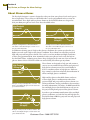
Continuous Monitoring Mode (Glucose CM)
The Continuous Monitoring mode is the mode you will use
most of the time. It continuously displays the glucose level in
the fluid in the tiny spaces between your tissues (interstitial
fluid). This glucose reading comes from the sensor you will
place just beneath your skin and is updated every minute.
• “Glucose CM” at the top left of the display.
• The glucose reading is typically accompanied by a
directional trend arrow that indicates how fast your glucose
is changing and in what direction.
• Most frequently used mode.
• Measures glucose from interstitial fluid detected by a
sensor in your skin.
–Uses a sensor to measure glucose levels.
–A transmitter sends the glucose readings to the receiver.
–Should only be used with FreeStyle Navigator system
Transmitters and FreeStyle Navigator Sensors.
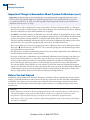
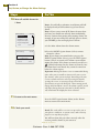
Blood Glucose Mode (Glucose BG)
Glucose BG
106
08:30A
mg/dL
Home
You will perform traditional blood glucose testing
(BG testing) in the Blood Glucose mode using a FreeStyle
Test Strip and a drop of blood. You can use the Blood Glucose
mode whenever you wish to perform a traditional blood
glucose test. It is also used for calibrating the system. Blood
Glucose mode tests used for calibrating the system can also
be relied on like traditional blood glucose tests.
• “Glucose BG” at the top left of the display.
–Built-in FreeStyle Blood Glucose Meter.
• Measures glucose from a blood sample that you supply.
• Uses a FreeStyle Test Strip to measure blood glucose levels.
Note: Use ONLY FreeStyle Test Strips and Control Solution.
FreeStyle Lite Test Strips will not work in the receiver.
Other brands of test strips or control solution can give you
inaccurate results.
The system typically works in the Continuous Monitoring mode. It switches to the Blood Glucose mode
when you insert a FreeStyle Test Strip into the receiver’s test strip port. In order to turn the Blood Glucose
mode on, you have to insert the test strip when the receiver is either turned off or when it displays the
glucose screen.
END OF Section 1
Customer Care: 1-866-597-5520
2 Install or Replace Transmitter and Receiver Batteries
Section 2 – Key Terms
n
Alarm
n
Icon
n
Receiver
n
Transmitter
n
Battery Life
n
Alkaline Batteries
n
357 HC Silver Oxide Battery
n
Reconnect
Customer Care: 1-866-597-5520
2
Section 2 15
Install or Replace Transmitter and Receiver Batteries
2 Install or Replace Transmitter and Receiver Batteries
Purpose
Start
To ensure that your FreeStyle Navigator system has power to operate properly.
Materials Gather these materials before you begin:
• 2 new AAA alkaline batteries for the receiver. We recommend Energizer® Max®,
Energizer® e2® Titanium®, and Energizer® Industrial batteries. Other batteries
may not provide expected battery life.
• 1 Silver Oxide 357 HC battery for the transmitter.
• A coin.
• Your FreeStyle Navigator Receiver.
• Your FreeStyle Navigator Transmitter.
Do this procedure:
• The first time you use your FreeStyle Navigator system.
• When the receiver displays the Low Battery message and alarm and the battery
icon
appears on the screen.
• When the receiver sounds an alarm and displays the “Replace TX Battery with
Next Sensor” message.
Helpful Information
Caution: It is important to use the correct type of batteries in the receiver, otherwise the battery life
may not be accurately monitored.
Important:
• An alarm will sound and a battery icon will appear on the screen when your receiver batteries are
running low. You must replace your receiver batteries the next time you replace your sensor. Make
sure to replace batteries before inserting your next sensor.
• An alarm will sound and a message will appear on the screen when your transmitter battery is
running low. You have approximately 4 days of battery power remaining when this first happens.
• Because you must insert a new sensor after each battery replacement, you should replace the
batteries just before you insert a new sensor. For example, if you drop your receiver and the
batteries fall out, you will have to insert a new sensor.
• After installing the transmitter or receiver batteries, allow a couple of minutes for the system to
recognize new batteries. You may then access the status of the battery life from the System menu in
your receiver (see Status Information in Section 10). If the batteries are new, the status screen will
show 75-100% as remaining battery life.
• If your receiver batteries are low and you fail to replace them, they may run out without a
warning and the receiver will neither display your glucose levels nor sound alarms.
• The transmitter’s battery life is estimated to be up to 30 days.
• The receiver’s battery life is estimated to be 60 days. However, battery life may be shorter than 60 days
if your receiver’s alarms are set to vibrate, if you use backlighting frequently, or if the transmitter/
receiver connection is broken often.
• If you will not be using your receiver for an extended period of time, remove the batteries from the
receiver to preserve battery life.
• To avoid draining the receiver’s batteries, be careful not to accidentally press and hold the receiver’s
buttons for a long period of time.
• After changing the batteries, make sure that you reconnect the transmitter and receiver to establish
communication between them.
• If you are replacing batteries on both the transmitter and receiver, replace the battery in the
transmitter first.
OVER
16 Section 2
Install or Replace Transmitter and Receiver Batteries
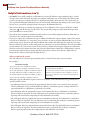
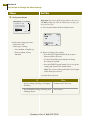
Install or Replace the Transmitter Battery
a. Turn the circular battery door counterclockwise with
either a coin or your fingernail. (Fig. 1)
Fig. 1
Fig. 2
b.Carefully remove the battery door.
c. Remove the old battery, if any, and discard it properly.
d.Insert a NEW silver oxide 357 HC battery with the plus
sign (+) facing you. (Fig. 2)
Important: When inserting the battery in the transmitter,
pay special attention to placing the battery straight in
rather than at an angle. Do not rock the battery back and
forth as this can shorten the battery life.
e. Replace the battery door and secure it in place by
rotating clockwise. (Fig. 3)
Fig. 3
Note: The battery door must be closed securely to
create a seal. Do not apply excessive force when
closing. Excessive force can damage the plastic material
of the battery door and the transmitter case. If you
are not changing the receiver batteries at this time,
reconnect the transmitter and receiver, then go to
‘Check your work’ at the end of this Section.
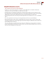
Install or Replace the Receiver Batteries
Note: The receiver skin must be removed in order to
access the receiver’s battery door.
a. Locate the battery door on the back of the receiver.
b.Press down on the ridged part of the battery door to
slide the battery door completely out.
c. Remove old batteries, if any, and discard them properly.
Battery door
Note: Be sure to finish within 5 minutes to prevent
losing the date and time settings.
d.Insert the new batteries with the positive (+) as shown.
Align the + and - signs of the batteries with the signs as
shown in the battery compartment.
e. Press each battery into its channel making sure the
battery fits tightly.
Note: The receiver will not operate if the batteries are
not inserted in the proper direction.
f. Replace the battery door with the tab facing the receiver.
g. Align the edges of the door with the channel in the
battery compartment.
h.Slide the door into the receiver until it clicks.
i. Match the screen on your receiver with ONE of the screens
in the next table and perform the corresponding step.
Customer Care: 1-866-597-5520
Section 2 17
Install or Replace Transmitter and Receiver Batteries
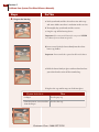
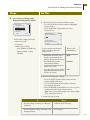
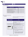
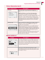
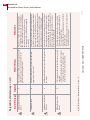
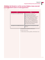
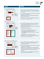
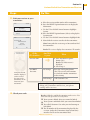
Match what you see on your Receiver with ONE of the screen
shots shown below.
If the display is
Then
•Press the RIGHT Option button to see if the screen
turns on.
•If screen turns on, compare with the screens below
and perform the matching steps.
•If screen does NOT turn on, then repeat this
procedure ensuring that the batteries are:
–New.
–Oriented properly in the battery compartment.
–If the problem persists see Section 10 on
troubleshooting.
Glucose CM
08:30A
•The receiver is working properly. Go to “Check your
work”. You may not see the
icon if you have
connection between the transmitter and receiver.
Reconnect the transmitter and receiver if you see the
icon.
Main
Set Date/Time
08:30A
08 : 30 A
05 - 10 - 2005
Next
Set
Select Mode
08:30A
Continuous Mode CM
Blood Glucose BG
BG
•The time and date need to be set. Go to Step 4 of
Section 3.
•Set the Time and Date. After setting the time and date,
reconnect the transmitter and receiver. Then, “Check
your work”.
•Select the mode that you want the system to operate in.
•Go to Section 14 to link the transmitter and receiver.
•Go to “Check your work”.
CM
OVER
18 Section 2
Install or Replace Transmitter and Receiver Batteries
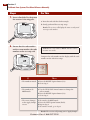
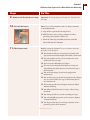
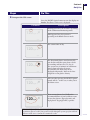
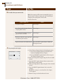
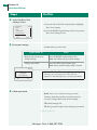
Reconnect the Receiver to the Transmitter.
System Menu
Reconnect
Data Upload
Status
Link
Set Date/Time
Main
08:30A
a.Place the receiver within 10 feet of the transmitter.
b.Press the RIGHT Option button twice to display the
Main Menu screen.
c. Use the UP or DOWN Arrow button to highlight System.
Select
d.Press the RIGHT Option button (Select) to display the
System menu with Reconnect highlighted.
e.Press the RIGHT Option button (Select).
f. Wait for the receiver to beep. If it beeps:
• Twice – The system is connected.
• Three times – The system is not connected. Make
sure the battery in the transmitter is new and ensure
that the receiver and transmitter are linked (see
Section 14).
Note: If the transmitter and receiver are connected
properly, the disconnect icon
will not appear on
the screen.
Check your work.
Result: An operational system.
You have done this procedure correctly when:
oThe batteries have been installed and the battery doors
have been closed securely.
oThe old batteries have been disposed of properly.
oThe transmitter and receiver have been reconnected.
END OF Section 2
Customer Care: 1-866-597-5520
3 Set the Time and Date
Section 3 – Key Terms
n
Left/Right Option Buttons
n
Main Menu
n
Receiver
n
System Menu
n
Transmitter
n
Up/Down Arrow Buttons
Customer Care: 1-866-597-5520
3
Section 3 21
Set the Time and Date
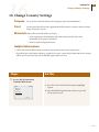
3 Set the Time and Date
Purpose To ensure the correct time and date are associated with your data.
Start
Do this procedure:
•The first time you use your FreeStyle Navigator system.
•When you install new batteries.
Materials
Your FreeStyle Navigator Receiver.
Helpful Information
Important: Be sure to set the date and time correctly. The correctness of the line graph and statistical
reports depends upon the date and the time being correct.
• The receiver is on whenever batteries with sufficient charge are in the receiver.
• If the batteries are discharged or removed for 5 minutes or more, you must reset the date and time.
• If you make a mistake or want to exit from the Set Date/Time screen, simply leave the receiver alone
for 12 seconds. It will automatically turn off, and any changes you made will be cancelled or cleared.
• If you change the time and/or date in the receiver, the line graphs and statistical reports will be
affected. For example, if you travel from one time zone to another and change the time to match the
local time zone, the appearance of your graph will be affected.
Steps
Do This
1. Go to the Main screen.
Glucose CM
08:30A
Note: When setting the time and date after inserting the
batteries, start from Step 4.
a.Turn the display on.
Main
b.Press the right Option button a second time to
display the Main screen. If your transmitter and
receiver are connected, you will not see the
icon.
OVER
22 Section 3
Set the Time and Date
Steps
Do This
2. Go to the System screen.
Main
Glucose
Alarms
Reports
System
Add Event
a. Press the down Arrow button to highlight System.
08:30A
b.Press the right Option button (Select) to go to the
System Menu screen.
Select
3. Select Set Date/Time from
the System Menu screen.
System Menu
Reconnect
Data Upload
Status
Link
Set Date/Time
Main
08:30A
a. Use the UP/DOWN Arrow buttons to highlight Set
Date/Time on the System Menu screen.
b. Press the right Option button (Select) to display the
Set Date/Time screen.
Select
4. Set the time.
a. Use the UP/DOWN Arrow buttons to set the
current hour.
b. Press the left Option button (Next) to move to
the minutes digits.
c. Use the UP/DOWN Arrow buttons to set the
current minutes.
d.Press the left Option button (Next) to move to
the AM or PM field.
e. Use the UP/DOWN Arrow buttons to select A
(AM) or P (PM).
f. To set the date, go to Step 5.
Customer Care: 1-866-597-5520
Steps
Section 3 23
Set the Time and Date
Do This
5. Set the date.
a. Press the left Option button (Next) to move to the
Month field.
b.Use the UP/DOWN Arrow buttons to set the current
month.
c. Press the LEFT Option button (Next) to move to the
Date field.
d.Use the UP/DOWN Arrow buttons to set the current
date.
e. Press the left Option button (Next) to move to the
Year field.
f. Use the UP/DOWN Arrow buttons to set the current
year.
g.Confirm that your selections are correct:
• If NO, press the left Option button (Next) and
repeat this procedure from Step 5a.
• If YES, press the right Option button (Set) to
accept your changes.
Result: The screen displays the System menu.
h.Press the left Option button (Main) to return to the
Main screen.
6. Check your work.
Result: Your FreeStyle Navigator Receiver is operating with
the correct time and date.
You have done this procedure correctly when:
o The time is correct.
o The date is correct.
END OF Section 3
Customer Care: 1-866-597-5520
4 Perform a Control Solution Test
Section 4 – Key Terms
n
Control Solution Test
n
FreeStyle Control Solution
n
FreeStyle Test Strips
n
Left/Right Option Buttons
n
Receiver
n
Up/Down Arrow Buttons
Customer Care: 1-866-597-5520
4
Section 4 27
Perform a Control Solution Test
4 Perform a Control Solution Test
Purpose Start
Materials
The purpose of the control solution test is to:
• Ensure that your receiver and test strips are working properly prior to calibration
or blood glucose testing.
• Check that you are following the correct testing procedure.
• Practice Blood Glucose mode testing without having to use your own blood.
A Control Solution test is not the same as a calibration. See Section 7 for
calibrating the system.
Do this procedure when you:
• Set up your receiver for the first time.
• Open and begin using a new vial of test strips.
• Suspect that your receiver or test strips are not working properly.
• Suspect that your glucose test results are not accurate.
• Suspect that your test results are not consistent with how you feel.
• Drop, damage, or expose the receiver to liquids.
• Are advised by your healthcare team to do so.
Gather these materials before you begin:
• FreeStyle Navigator Receiver.
• FreeStyle Control Solution.
• FreeStyle Test Strips.
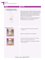
Helpful Information
Caution:
• Do NOT use FreeStyle Control Solution for calibration. Do NOT perform the control solution test
when the system asks you to ‘Do BG Test’ for calibration.
• Results from Control Solution tests do NOT reflect your blood glucose level.
Important: The control solution range is a target range for the control solution only. It is NOT a target
range for your blood glucose levels.
Important: If your control solution test results continue to fall outside of the range printed on the test
strip vial, the receiver may not be working properly. Do NOT use the system to test your glucose levels.
Call Customer Care.
Ensure accurate control solution results by doing the following:
• Use ONLY FreeStyle Control Solution and FreeStyle Test Strips.
• Replace the cap on the control solution vial immediately after using.
• Do NOT use your control solution past the expiration date or the discard date.
• Do NOT add water or any liquid to the control solution.
• Perform control solution tests only between 59° and 104° F (15° and 40° C).
For important test strip information, including detailed storage and usage information, refer to the
FreeStyle Test Strip package insert.
OVER
28 Section 4
Perform a Control Solution Test
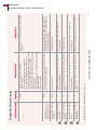
Steps
Do This
1. Verify that your FreeStyle
Control Solution is current.
Note: FreeStyle Control Solution is good for three months
after opening the bottle, or until the expiration date printed
on the label, whichever comes first. Count forward three
months from the date you open a new bottle of control
solution. This is your discard date. Write this date on the
side of the control solution bottle.
Example: You open the control solution on January 15th.
Count forward three months to April 15th. This is the
discard date that you record on the bottle.
2. Prepare test strip.
a.Locate the expiration date on the vial of FreeStyle
Test Strips.
If strips are expired, obtain a new vial of strips.
b.Locate the code number (you’ll need it in a minute).
c.Remove a single test strip from the vial.
d.Close the vial tightly before continuing but do NOT
put the vial away.
Customer Care: 1-866-597-5520
Section 4 29
Perform a Control Solution Test
Steps
Do This
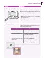
3. Insert test strip into the receiver.
a.Turn the test strip so “FreeStyle” text faces up.
b.Grasp the test strip by the end with the two half circles.
c.Insert the end with the dark rectangle into the receiver
at the lower left corner of the receiver.
Result: The receiver display screen turns on and displays
the Strip Code screen.
Note: If the screen does not turn on, refer to Section 10
on troubleshooting.
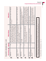
4. Compare code numbers.
Compare the code number on the display with the code
number on the vial of test strips.
If
Then
•The numbers match.
a. Press the right Option button (Set).
b. Go to Step 5.
•The numbers do NOT match.
a. Use the UP/DOWN Arrow buttons to
change the code to match.
b. Press the right Option button (Set).
c. Go to Step 5.
•The screen changes to the Apply
Sample screen.
If the numbers did NOT match:
a. Press the left Option button (Back).
b. Repeat Step 4.
If the numbers match, go to Step 5.
Strip Code
08:30A
27
Cancel
Set
OVER
30 Section 4
Perform a Control Solution Test
Steps
Do This
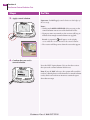
5. Apply control solution.
Important: Do NOT apply control solution to both edges of
the test strip.
Apply Sample
Back
08:30A
Notes:
• Gently touch ONLY ONE EDGE of the test strip to the
control solution next to one of the dark half-circles.
Cancel
• If progress tones are turned on, the receiver will beep to
indicate that enough control solution was applied.
Result: A stopwatch
will appear on the display
screen while the receiver measures the control solution.
• The receiver will beep twice when the test results appear.
6. Confirm that you used a
control solution.
Press the left Option button (Yes) to alert the receiver
that you used a control solution for this test.
Glucose BG
106
08:30A
mg/dL
Control Solution?
Yes
No
Note: If you do NOT select yes, the system will record the
result as a blood glucose result instead of a control solution
result, which can result in an incorrect statistical report.
Go to the next step.
Customer Care: 1-866-597-5520
Section 4 31
Perform a Control Solution Test
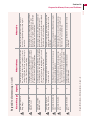
Steps
Do This
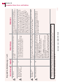
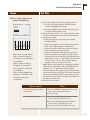
7. Evaluate the test results.
Compare the test results displayed on the screen to the
range printed on the vial of test strips.
If the result
Then
•Falls WITHIN the
range.
➜
•Falls OUTSIDE of
the range.
You’ve repeated
the test.
Call Customer Care.
You’ve NOT
repeated the test.
Repeat the test from Step 1 with a
NEW test strip.
•Is an error message.
Glucose BG
106
And
➜
Go to Step 8.
Go to Section 10 on
troubleshooting.
08:30A
mg/dL
Control Solution?
Yes
No
77 – 115 mg/dL
8. Check your work.
Result: Control solution test results displayed on the
receiver screen.
You have done this procedure correctly when:
o The results are within the normal control solution range.
o The used test strips have been discarded properly.
o The control solution tests are marked as control
solution tests.
END OF Section 4
Customer Care: 1-866-597-5520
5 Insert or Remove Your Sensor
Section 5 – Key Terms
n
Calibration
n
Sensor Inserter
n
Sensor Release Tabs
n
Reconnect
n
Sensor Insertion Button
n
Sensor Support Mount
n
Sensor
n
Sensor Insertion Site
n
Sharps Container
n
Sensor Delivery Unit
n
Sensor Locking Pin
n
Transmitter Receiver Connection
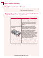
Now that you are ready to insert a sensor, here are a few helpful tips.
• Reconnect your transmitter and receiver BEFORE inserting a new sensor.
• BEFORE inserting a new sensor, program into the receiver that the old sensor has been
removed.
• Make sure there are no messages or icons related to low battery conditions on the receiver
BEFORE inserting a sensor.
• When attaching the transmitter, you may not always hear a click. Place the transmitter
about halfway over the sensor support mount and slide the transmitter back and forth to
make sure it moves freely before you attach it. You will feel a click as you slide it into place.
• After attaching the transmitter to a new sensor, allow the system a few minutes to
recognize a new sensor. Reconnect the receiver and transmitter to make sure they are
communicating.
• When responding to messages about sensor insertion and sensor removal, choose the
appropriate answer (‘Yes’ or ‘No’).
• Do NOT use the Link/Unlink feature unless you have received a new transmitter or
receiver from the manufacturer. To establish communication between them, ALWAYS use
the ‘Reconnect’ feature. {Note: Link is NOT the same as Reconnect}
• Avoid errors and messages related to calibration by following a few simple guidelines:
• Do NOT calibrate if your blood glucose is higher than 300 mg/dL (16.7 mmol/L) or
lower than 60 mg/dL (3.3 mmol/L).
• If you have just exercised, eaten or taken insulin, your glucose levels may be changing
rapidly. Allow about an hour for the glucose levels to reach a relatively steady state
before calibrating.
• The system automatically detects conditions that may not be suitable for calibration. It
may delay calibration requests in such instances. Wait for the system to prompt you and
LOOK for the
icon on the screen.
• It is normal during typical usage to get multiple messages about failed calibrations (“Cal
Failed”) or additional calibration requirements (“Cal Required”). The system automatically
evaluates conditions for calibration and displays appropriate messages if those conditions
are not met or if the calibrations fail. This helps maintain system accuracy. When you get
these messages, simply follow the prompts on the screen or guidelines in the User’s Guide.
If you get too many messages, please call Customer Care.
• Do NOT change batteries during a sensor wear. Changing the batteries resets the system
and will force you to remove the sensor.
If you need assistance, please call Customer Care.
Customer Care: 1-866-597-5520
5
Section 5 35
Insert or Remove Your Sensor
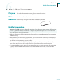
5 Insert or Remove Your Sensor
Purpose
To insert, remove, or replace a small, thin, plastic sensor under your skin so that your
FreeStyle Navigator system can continuously monitor your glucose level.
Start
Do this procedure:
• The first time you use your FreeStyle Navigator system.
• Every 5 days after that.
• Replace your sensor sooner than 5 days when:
–There is any redness, pain, tenderness, or swelling at the insertion site.
–An error code displays on your receiver indicating a sensor problem.
• When replacing batteries.
Materials
Gather these materials before you begin:
• Soap and water.
• Alcohol prep pads.
• A sensor delivery unit in its UNOPENED package.
• Your transmitter.
• Your receiver.
Helpful Information
Important: Keep the following in mind when inserting your sensor.
• You will not have continuous monitoring data until you have successfully completed the first
calibration (at least for the first ten hours after sensor insertion).
• You may not be able to calibrate the system if your glucose levels are changing rapidly. For example,
during a meal or exercise, your glucose levels may vary rapidly. Try to time your insertion so that
your calibration times do not coincide with your regular meal or exercise activities.
Note: You should keep your sensor inserted for 5 days. See the exceptions listed above under Start.
•The system will ask you to perform 4 calibrations at approximately -10, 12, 24 and 72 hours after
inserting a new sensor (See Section 7).
•You MUST change your sensor every 5 days, to reduce the chance of infection. The system
automatically terminates a sensor session after 5 days. Do NOT leave the sensor inserted for more
than 5 days.
•Taking action at the first sign of irritation or discomfort will keep small issues from turning into
larger or ongoing ones.
•You may not be able to perform the calibration after you eat until your glucose levels stabilize.
•See Appendix A: Site Maintenance for additional helpful suggestions.
•Before inserting a new sensor make sure that there are no low battery messages displayed on the
receiver. This will help avoid data loss after the insertion if the batteries are running low.
Interferents: In vitro and in vivo testing suggest that usual pharmacologic levels of ascorbic acid have
no effect on the function of the system but salicylic acid has minimal effect. In vitro testing suggests
that normal physiologic levels of uric acid, lipids, and bilirubin do not affect system function. The
impact of oral hypoglycemic agents and other potential interfering substances has not been studied.
OVER
36 Section 5
Insert or Remove Your Sensor
Important Things to Know About Getting Reliable Results
Caution: Movement of the sensor support mount or excessive perspiration at the sensor insertion site due
to activities like vigorous exercise or bumping against objects may lead to poor adhesion of the support
mount to the skin and then cause the sensor to dislodge. If the sensor dislodges due to the sensor support
adhesive failing to adhere to the skin, you may get unreliable results or no results. The system may not
provide a warning in such circumstances. Choose the proper sensor insertion site when inserting the
sensor and prepare the site by following the instructions for site preparation.
Caution: If your results from the Continuous Monitoring mode seem erroneous, check and make sure
that the sensor has not dislodged. If you notice the sensor is dislodged from the skin, or if you see that the
adhesive on your overbandage or the sensor support mount is coming loose, discard the old sensor and
insert a new sensor.
Steps
Do This
1.Decide what to do.
If you want to Then
•Change or remove your sensor.
Go to Step 2.
•Insert your sensor.
Go to Step 4.
Customer Care: 1-866-597-5520
Section 5 37
Insert or Remove Your Sensor
Steps
Do This
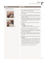
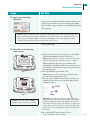
2.Remove the sensor.
a.Wipe a small amount of isopropyl alcohol around the
edges of the sensor support mount.
Note: You can use a regular alcohol prep pad from your
local drugstore.
Fig. 1
Fig. 2
b.Grasp the top end of the adhesive (the end nearest the
sensor, see Fig.1) and slowly peel it off your skin in one
continuous motion.
c. Pull down on the adhesive at the bottom of the support
mount (the end farthest from the sensor, see Fig.2). You
will hear a click as the transmitter separates from the
support mount.
d.Discard the sensor support mount (with the sensor
attached).
Important:
•3 Do NOT discard the transmitter.
•3 NEVER reuse the sensor support mount and sensor.
e.Gently wash the transmitter with soap and water.
f. Dry the transmitter thoroughly with a clean, soft, lintfree cloth. Be sure that you blot the sensor connector on
the end of the transmitter.
g.If necessary, use an alcohol wipe prep pad, baby oil, or
a wet, soapy washcloth to remove any adhesive left on
your arm.
h.Dry your arm with a clean dry towel before continuing.
Important:
Do NOT use adhesive remover wipes containing ether or
ether-containing components to remove adhesive residue
from the transmitter. Adhesive remover solutions such
as Uni-Solve® and others that contain ether components
can damage the transmitter case. We recommend using
regular alcohol pads for cleaning adhesive residues.
i. Proceed to next step to end sensor session.
OVER
38 Section 5
Insert or Remove Your Sensor
Steps
Do This
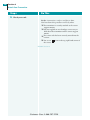
3.End sensor session.
a. Press the RIGHT Option button twice to get to the
Main menu.
b. Press the UP/DOWN Arrow button to highlight System.
c. Press the RIGHT Option button to select System.
d. Press the UP/DOWN Arrow button to highlight Status.
e. Press the RIGHT Option button to select Status.
f. Press the RIGHT Option button to select Removed Sensor.
g. Press the RIGHT Option button to select Yes. The
system now knows you have removed the sensor. If you
are going to replace your sensor now, continue to Step 4.
08:30A
Did You Remove
The Sensor?
No
Yes
4.Reconnect the receiver to
the transmitter.
System Menu
Reconnect
Data Upload
Status
Link
Set Date/Time
Main
08:30A
Select
5.Select an insertion site.
Abdomen
Back of upper arm
a. Place the receiver within 10 feet of the transmitter.
b. Press the RIGHT Option button twice to display the
Main Menu screen.
c. Use the UP/DOWN Arrow button to highlight System.
d. Press the RIGHT Option button (Select) to display the
System menu with Reconnect highlighted.
e. Press the RIGHT Option button (Select).
f. Wait for the receiver to beep. If it beeps:
• Twice – The system is connected.
• Three times – The system is not connected. Make sure
the battery in the transmitter is new and ensure that
the receiver and transmitter are linked (see Section 14).
Note: If the transmitter and receiver are connected
properly, the disconnect icon
will not appear on
the screen.
Caution: If the sensor dislodges due to the sensor support
adhesive failing to adhere to the skin, you may get unreliable
or no results. Improper site selection and improper site
preparation may cause poor adherence to the skin.
Notes:
• Select a site ONLY on the back of the upper right arm, on
the back of the upper left arm, or on your abdomen.
• Do NOT insert the sensor where another sensor was just
removed (See “Site Selection” in Appendix A).
• Rotate where you insert your sensor across several sites.
• Avoid areas where the edges of clothing may catch or rub
against the sensor.
• Avoid areas with scars, moles, stretch marks, or lumps.
• Select an area of skin that stays flat during your normal
daily activities (no bending or creasing).
• Avoid areas with excess hair, or consider shaving the area.
• Choose a site that is at least 1 inch away from an insulin
infusion site.
Customer Care: 1-866-597-5520
Steps
Section 5 39
Insert or Remove Your Sensor
Do This
6.Prepare the insertion site.
a.Wash your hands thoroughly with soap and water.
b.Clean the selected insertion site area with soap
and water.
c.Rinse the area thoroughly and pat dry.
d.Wipe the area with an alcohol prep pad.
Note 1: The insertion area MUST be clean and dry.
Otherwise:
• An infection could occur.
• The sensor support mount may not stick to the site.
Note 2: Do NOT place a bandage on the insertion
site before inserting the sensor. The sensor may not
penetrate the skin and the system will not work with a
bandage under the sensor.
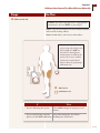
7.Remove the sensor delivery
unit from package.
Caution: Do NOT use the sensor delivery unit if the
sterile package is open or damaged.
a. Remove the sensor delivery unit from its sterile package
by peeling off the foil on the back of the package.
b.Save the package.
Note: You will need the sensor code number on the back
of the package, later.
Important: We recommend that you save the sensor kit
carton or the sensor sterile package until the last sensor
from your sensor kit has been used and discarded. Saving
the package will help you to have sensor lot information,
expiration dates and sensor code etc. accessible when you
need them.
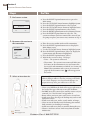
8.Remove the protective liner from
the sensor support mount.
a. Bend the two-piece protective liner slightly so you can
see the seam between the two pieces.
b.Peel away the smaller section.
c. Peel away the larger section.
OVER
40 Section 5
Insert or Remove Your Sensor
Steps
Do This
9.Attach the sensor delivery unit
to your skin.
a.Locate the top of the sensor support mount.
b.Follow the instructions below as you place the
sensor support mount, adhesive-side down, on
the insertion site:
Top of the Sensor
Support Mount
If you are
Then
•Inserting the sensor on the
back of your arm.
Place the sensor support mount lengthwise
on your arm with the top of the sensor
support mount facing your shoulder.
•Inserting the sensor on your
abdomen.
Place the sensor support mount horizontally
on your abdomen.
10. Ensure that the adhesive pad is
adhered to your skin.
a. Hold the sensor delivery unit firmly in place.
b.Smooth the adhesive pad against your skin.
Customer Care: 1-866-597-5520
Steps
Section 5 41
Insert or Remove Your Sensor
Do This
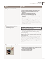
11. Remove the locking pin.
a. Grasp the top of the locking pin with your thumb and
index finger.
b. Twist the locking pin a 1/4
turn in either direction until
the locking pin clicks.
c. Pull the locking pin away to
remove it.
Note: The sensor support mount adhesive will help
keep the sensor support mount in place.
12. Insert sensor.
Caution: Do NOT press the button until you are ready
to insert the sensor. Doing so may cause unintended
results or injury.
a. Hold the sensor inserter as shown and press down on
both sides of the button at the same time.
Important: Do NOT press on the blue release tabs while
pressing the button on the top of the inserter.
Note: You will feel a slight pinch as the sensor is placed
just under your skin.
13.Remove inserter
a. Hold the sensor inserter and firmly squeeze the two
blue release tabs at the inserter’s base, as you lift the
inserter away from the sensor support mount.
Note: Do NOT lift the inserter without squeezing
the blue release tabs as this may dislodge the sensor
support mount.
Blue Release Tab
OVER
42 Section 5
Insert or Remove Your Sensor
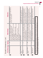
Steps Do This
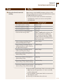
14. Check the sensor support
mount.
a. Confirm the sensor support mount remains tightly
adhered to your skin by sliding your finger along the
edges of the adhesive pad and examine for any gaps
in adhesion.
b.Examine the area for a drop of blood. You may
see some blood from the insertion site. If there is
continuous bleeding that does not stop in a few
minutes even after blotting with a clean cloth or
swab, repeat the procedure from Step 2 to remove the
sensor support mount, select a new site and insert a
NEW sensor.
c. Use a mirror to check that sensor is correctly placed.
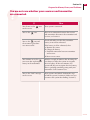
If
Then
Sensor is correctly placed. You will see the
tip of the sensor is inserted under the skin
and the sensor is flush against the top edge
of the sensor support mount.
Sensor is missing.
1. Remove sensor support mount.
2. Go to Step 1 to insert a new sensor.
Customer Care: 1-866-597-5520
Steps
Section 5 43
Insert or Remove Your Sensor
Do This
15. Discard the sensor inserter
safely. We recommend a sharps container or a puncture-proof container with a tight lid.
16. Check your work.
Result: An inserted sensor, a removed sensor, or a
replaced sensor.
You have done this procedure correctly when:
o The system successfully recognized that you removed
a sensor (if you removed a sensor).
o The site was selected and prepared according to the
guidelines given in this procedure.
o The receiver and transmitter were reconnected
successfully.
o
The sensor support mount is tightly adhered to either
your abdomen or the back of your upper arm.
o
The sensor is inserted in a site that is different from
the site that was used for the last sensor.
o
o
The sensor is visible with the tip inserted into your skin.
The sensor inserter is disposed safely.
END OF Section 5
Customer Care: 1-866-597-5520
6 Attach Your Transmitter
Section 6 – Key Terms
n
Left/Right Option Buttons
n
Receiver
n
Sensor Code
n
Sensor Support Mount
n
System
n
Transmitter
n
Up/Down Arrow Buttons
Customer Care: 1-866-597-5520
6
Section 6 47
Attach Your Transmitter
6 Attach Your Transmitter
Purpose
To enable the transmitter to send glucose data to the receiver.
Start
Do this procedure after inserting a new sensor.
Materials
Your FreeStyle Navigator Transmitter with battery installed.
Helpful Information
Important: Do NOT remove or replace the transmitter from the sensor support mount while wearing
a sensor. If you notice that the transmitter is not properly attached, replace the sensor with a new
sensor and then re-attach the transmitter.
• Make sure that you establish communication between the receiver and transmitter by reconnecting
them if necessary.
• After you attach your transmitter, you must keep your receiver within 10 feet of the transmitter to
maintain a consistent connection. If the connection between the transmitter and receiver is broken
you will not receive continuous glucose readings.
• The connection can also be affected by objects getting between the transmitter and receiver, by
nearby large metal objects, and by some electronic devices that produce radio frequencies.
• If a connection alarm sounds, move the transmitter closer to the receiver to restore the connection.
If you have trouble with the connection between the transmitter and receiver, see Section 10 on
troubleshooting.
OVER
48 Section 6
Attach Your Transmitter
Steps
Do This
1. Attach the transmitter to the
sensor support mount.
a.Position the transmitter over the sensor support mount
so that the battery side faces the mount.
b.Lower the transmitter onto the mount.
Note: It helps to position the transmitter’s connector
directly over the round part of the “keyhole” (Fig. 1)
as you lower the transmitter.
Fig. 1
Result: The transmitter fits flush against the mount
and slides smoothly back and forth on the guide rails.
c.Hold the transmitter between your forefinger and thumb
and slide the transmitter until it clicks into place. Apply
firm pressure as you slide the transmitter into place.
(Fig. 2)
Note: It is normal to see a gap between
the transmitter and the support mount
towards the top.
Fig. 2
2.Confirm the transmitter
is correctly attached to the
sensor support mount.
a.Look at the side of the transmitter where the bottom
sits on the guide rails.
b.Is there a space between the bottom edge of the
transmitter and the top edge of the guide rails?
If Then
• No
The transmitter is correctly attached. Go to Step 3.
• Yes
1.Go to Section 5 to replace your sensor.
2.Repeat this procedure to attach your transmitter.
Customer Care: 1-866-597-5520
Section 6 49
Attach Your Transmitter
Steps
Do This
3.Apply an over-bandage
(Optional).
Apply an over-bandage to hold down the transmitter and
sensor support mount. Use an over-bandage if you find
that the sensor support mount is not adhering well during
daily activities.
Caution: If your results from the Continuous Monitoring mode seem erroneous, check and
make sure that the sensor has not dislodged. If you notice the sensor is dislodged from the
skin, or if you see that the adhesive on your overbandage or the sensor support mount is
coming loose, discard the old sensor and insert a new sensor.
Go to the next step.
4. Enter the sensor code into
your receiver.
a.When you hear the receiver beep, press the RIGHT
Option button once to turn the receiver on.
08:30A
New Sensor Detected
Have You Recently
Inserted a New Sensor?
No
Yes
Result: The receiver screen says, “New Sensor Detected
Have You Recently Inserted a New Sensor?” (Fig. 1)
Note: Typically, it may take up to 3 minutes after
attaching the transmitter before the receiver beeps. See
Section 10 to troubleshoot if you do not get the sensor
detection message.
b.Press the RIGHT Option button (Yes).
Fig. 1
Note: If you ever see this message at any other time,
press the LEFT Option button (No).
Sensor Code
08:30A
105
Cancel
c.Press the UP or DOWN Arrow button to change the
number on the receiver screen to the number on the
packaging. (Fig. 2).
Set
Fig. 2
Caution: The code numbers MUST
match to ensure accurate test results.
Important: Once the code has been entered and you
have hit the Set button as instructed below, you will not
be able to change the sensor code number. If you have
entered the code incorrectly, you will have to replace the
sensor and enter the right sensor code. If you choose the
wrong sensor code, you may get erroneous results from
the sensor.
d.Press the RIGHT Option button (Set) to
accept the number on the screen.
OVER
50 Section 6
Attach Your Transmitter
Steps
Do This
5. Check your work.
Result: A transmitter ready to send glucose data.
You have done this procedure correctly when:
o The transmitter is securely attached to the sensor
support mount.
o You have applied an over-bandage as necessary to
hold down the transmitter and the sensor support
mount.
o The sensor code has been correctly entered into the
receiver.
o You see an
the screen.
icon on the top right hand corner of
END OF Section 6
Customer Care: 1-866-597-5520
7 Calibrate Your System/Test Blood Glucose Manually
Section 7 – Key Terms
n
BG Mode
n
Calibrate
n
Calibration BG
n
Control Solution
n
FreeStyle Test Strips
n
Icon
n
Lancet
n
Lancing Device
n
Lancing Device Cocking Handle
n
Lancing Device Depth Indicator Window
n
Lancing Device Depth Setting
n
Lancing Device Lancet Cup Holder
n
Left/Right Option Buttons
n
Receiver Test Strip Port
n
Sharps Container
n
Up/Down Arrow Buttons
Customer Care: 1-866-597-5520
7
Section 7 53
Calibrate Your System/Test Blood Glucose Manually
7 Calibrate Your System/Test Blood Glucose Manually
Purpose
Start
Materials
To ensure the receiver will calculate your glucose readings accurately.
Do this procedure:
• Each time the receiver prompts you with the message, “Do BG Test.” You will
see a blood drop icon
on the screen and you will also hear the system beep
(or vibrate).
• When you need to measure your blood glucose manually using the built-in
FreeStyle Meter.
• Soap, water, and a clean towel. •FreeStyle Test Strips.
• A FreeStyle Lancing Device.
•Your FreeStyle Navigator Receiver.
• Sterile lancets.
•A sharps container.
Helpful Information
Important Things to Remember About System Calibration
• The system is calibrated using a capillary whole blood glucose measurement (performed in the Blood
Glucose mode using the built-in FreeStyle Blood Glucose Meter). In order to calibrate, the receiver
compares the reading it gets from the blood to the reading the sensor takes from the interstitial fluid.
Based on the calibration, the receiver calculates the glucose readings.
• Do not use venous blood for calibrating the system.
Caution: Always calibrate the system only using a finger-stick blood sample. Do NOT use alternate
site blood glucose measurements to calibrate the system. The receiver contains a built-in FreeStyle®
Blood Glucose Meter for performing calibration tests.
Important: Your blood glucose level must be between 60 and 300 mg/dL (3.3 and 16.7 mmol/L) to be
able to perform calibration tests. If your blood glucose level is changing rapidly, you may not be able
to calibrate the system. For example, during a meal or exercise, your glucose levels may vary rapidly.
Try to time your sensor insertion so that your calibration times do not coincide with your regular
meal or exercise activities.
Important: In clinical trials, we observed that the sensor signal sometimes temporarily decreases
from the true value. This typically happens at night during sleep, and recovers rapidly when the user
moves or is awakened. However, in order to avoid being affected by this phenomenon the system
should not be calibrated when the wearer is asleep.
• You may not be able to calibrate the system if your glucose levels are changing rapidly (e.g. during
or after exercise, meals or insulin dosing). Under such conditions, the system may not ask you to
calibrate; instead, it will delay its request until conditions are acceptable.
OVER
54 Section 7
Calibrate Your System/Test Blood Glucose Manually
Helpful Information (con’t)
• You MUST successfully complete 4 calibration tests. You will calibrate at approximately 10, 12, 24 and
72 hours after sensor insertion. If you do not complete calibration tests successfully in the allotted time
periods, your glucose readings will NOT be displayed and alarms will be inactive. The system may ask
you to perform additional calibrations between 2nd and 3rd calibrations depending on the sensor signal.
In such cases, you will be prompted with a message to do additional BG tests.
• The receiver will beep (or vibrate) to prompt you to do a calibration. The receiver will display a blood
drop icon
and the message “Do BG Test.” The system will prompt you with alarm messages when
your calibrations are unsuccessful.
• You will not have continuous monitoring until you have successfully completed the first calibration (at
least for the first ten hours after sensor insertion).
• If you get a request for a calibration or expect additional calibration requests during a time when you do
not want to be disturbed (e.g. sleep time), you can choose to wait to perform additional BG tests at a later
point in time. If you choose to wait and the allotted time window for calibration has expired, please note
that you will not get glucose results until you have performed a successful calibration. You can turn off the
System Alarms (or set to vibrate) if you do not want to be disturbed by frequent requests for calibration.
In order to silence the alarms that warn you when the allotted time window for a calibration has expired,
you must turn off the data loss alarms and all the four glucose alarms (Low Glucose, High Glucose,
Projected Low Glucose and Projected High Glucose).
When to calibrate the system?
You will calibrate the system at approximately 10, 12, 24 and 72 hours after sensor insertion.
For example:
Insertion at night
If you insert the sensor at 9:00 pm on Day 1,
the first calibration would be at 7:00 am on Day 2,
the second calibration would be at 9:00 am on Day 2,
the third calibration would be at 9:00 pm on Day 2,
the fourth calibration would be at 9:00 pm on Day 4.
Sensor removal would be at 9:00 pm on Day 6.
What happens in the example if the first calibration does
not occur until 9 am on Day 2?
The 2 hour delay will add on to the second, third and fourth
calibration. Second calibration will now happen at 11 am on
day 2 and so on. However, sensor removal will still happen at
9 pm on Day 6.
Although a typical calibration sequence will occur as shown, each calibration has to be performed in a
specific window of time.
• 1st calibration: Must be performed at approximately 10 hours after a new sensor has been inserted.
The first calibration can be performed after the 10 hours. Continuous glucose readings will NOT be
reported until the 1st calibration is performed successfully.
• 2nd calibration: Must be performed between 2 and 4 hours after the 1st calibration or continuous
glucose will not be reported. The 2nd calibration can be performed after 4 hours; continuous glucose
reporting will resume after completing the 2nd calibration successfully.
• 3rd calibration: Must be performed between 12 and 20 hours after the 2nd calibration or continuous
glucose will not be reported. The 3rd calibration can be performed after 20 hours; continuous glucose
reporting will resume after completing the 3rd calibration successfully.
• 4th calibration: Must be performed between 48 and 56 hours after the third calibration or continuous
glucose will not be reported. The fourth calibration can be performed after 56 hours; continuous
glucose reporting will resume after completing the 4th calibration successfully.
Customer Care: 1-866-597-5520
Section 7 55
Calibrate Your System/Test Blood Glucose Manually
Helpful Information (con’t)
Some common reasons for unsuccessful calibrations
• Your BG test result is below 60 mg/dL (3.3 mmol/L) or above 300 mg/dL (16.7 mmol/L). Perform the
calibration test when your blood glucose is within the above range.
• Your blood glucose is changing too rapidly. This can happen during a meal or exercise activities or if you
have taken insulin. Give yourself an hour before you try to perform a calibration test again. Do not perform
a Blood Glucose mode test for calibration if you do not see the blood drop icon on the screen.
• The skin temperature may be out of range (the skin temperature has to be between 77° F (25° C) and 104° F
(40° C).
• The sensor signal may be out of range or has changed relative to the last successful calibration.
• Improper Blood Glucose mode testing. Carefully follow the instructions in this Section to perform a BG
test (keep your hands clean, enter the right strip code and choose finger for calibration tests) to avoid errors
from the Blood Glucose mode test.
The system will prompt you with alarm messages when your calibrations are unsuccessful. See Section 10
for more information or call Customer Care. You will have to perform additional Blood Glucose mode tests
(BG tests) if your calibrations are unsuccessful.
OVER
56 Section 7
Calibrate Your System/Test Blood Glucose Manually
Steps
Do This
1. Insert a FreeStyle Test Strip into
the receiver’s test strip port.
a.Insert the end with the dark rectangle.
b.Gently push until the test strip stops.
Result: The receiver will display the most recently used
test strip code number.
2. Ensure that the code number
on the screen matches the code
number on the test strip vial.
Strip Code
Cancel
Caution: The code numbers MUST match to ensure
accurate test results.
Compare the code number on the display with the code
number on the vial of test strips.
08:30A
Set
If
Then
• The numbers match. a.Press the RIGHT Option button (Set).
b.Go to Step 3.
• The numbers do
NOT match.
a.Use the UP/DOWN Arrow buttons to change the
code to match.
b.Press the RIGHT Option button (Set).
c.Go to Step 3.
• The screen changes to the Apply Sample
screen.
If the numbers do NOT match:
a.Press the LEFT Option button (Back).
b.Repeat Step 2.
If the numbers match, go to Step 3.
Result: The receiver will prompt you to “Apply Sample.”
Customer Care: 1-866-597-5520
Section 7 57
Calibrate Your System/Test Blood Glucose Manually
Steps
Do This
3. Select a test site.
Caution: If you have hypoglycemia, or hypoglycemia
unawareness, then test ONLY on your fingers.
Note 1: Vary the sites from test to test to avoid tenderness
and to avoid creating calluses.
Note 2: Avoid moles, veins, bones, and tendons.
Caution: Always calibrate the
system using only a finger-stick
blood sample. Do NOT use
alternate site blood glucose
measurements to calibrate the
system. The receiver contains
a built-in FreeStyle® Blood
Glucose Meter for performing
calibration tests.
n BG Test Site
Calibration sites
If
Then
• You are calibrating the system.
Select ONLY a finger for testing (see red
circles).
• You are simply doing a manual
Select from among the sites shown
glucose test and NOT calibrating. including the circled areas.
OVER
58 Section 7
Calibrate Your System/Test Blood Glucose Manually
Steps
Do This
4.Prepare for lancing.
a.Wash your hands and the selected test site with soap
and water. Make sure there is no lotion on the test site.
b.Thoroughly dry your hands and the test site.
c.Snap the cap off the lancing device.
Important: Use a new sterile lancet for every test. NEVER
use a lancet for more than one person.
d.Insert a new FreeStyle Lancet firmly into the white
lancet cup holder.
Important: Do not touch the exposed needle on the lancet.
e.Hold the lancet firmly in place with one hand and use
your other hand to twist off the rounded top.
f. Replace the cap until it snaps or clicks into place.
If your test site is
Then
• A finger.
Use the grey cap.
• Your forearm or a test site other
than the finger.
Use the clear cap.
Customer Care: 1-866-597-5520
Section 7 59
Calibrate Your System/Test Blood Glucose Manually
Steps
Do This
4. Prepare for lancing. (con’t)
g.Select the lancing device depth setting.
If you are lancing
Then
• A finger.
Set the depth setting to its shallowest depth (1).
• Your forearm.
Start at Level (2) or higher if your experience with
setting 2 does not produce a usable sample.
• The FreeStyle® Lancing Device offers four different depth
settings. Move the dial to the desired setting as shown
in the depth indicator window. Level 1 is the shallowest
depth; Level 4 is the deepest. To lance parts of the body
other than the finger, we recommend that you start at
Level (2) and use the clear cap.
To lance your finger, we recommend that you set the
depth setting to its shallowest depth (1) and use the
grey cap.
h.Pull the dark grey cocking handle out until it clicks.
Note: You may have already cocked the device in Step 4d.
i. Prepare the site:
If you are using
Then to stimulate blood flow
• A finger.
Warm your hand, lower it to waist level, and
gently massage the finger.
• Your forearm.
Rub the test site vigorously until you feel it getting
warm (three to five seconds).
OVER
60 Section 7
Calibrate Your System/Test Blood Glucose Manually
Steps
Do This
5.Lance the site.
To lance your finger (grey cap):
a. Lightly touch the lancing device against the side of
your fingertip.
b.Press the release button.
c. Put the lancing device down.
d.Gently squeeze your finger, if needed, until a drop of
blood the size of a pinhead forms.
To lance your forearm (clear cap):
a. Hold the lancing device against the test site.
b.Press the release button.
c. Continue to hold the lancing device against the test
site as you:
i) Inspect the test site through the clear cap.
ii)Gradually increase pressure until the sample is the
size of this dot:
Important: Do NOT smear the sample as you do the
next step.
d.Lift the lancing device straight up.
Customer Care: 1-866-597-5520
Section 7 61
Calibrate Your System/Test Blood Glucose Manually
Steps
Do This
6. Test the sample.
Do Not:
•Use test strips more than once. Discard used test strips.
•Scrape the blood.
•Apply blood to the flat side of the test strip.
•Apply blood to the test strip when the test strip is out of
the receiver.
•Apply blood to both edges of the test strip.
•Put blood or foreign objects into the receiver’s test
strip port.
a.Holding the receiver at a slight angle to the sample, gently
touch the half-circle on the test strip to the sample.
Proccessing
Important: Your blood glucose level must be between 60 and
300 mg/dL (3.3 and 16.7 mmol/L) to be able to perform
calibration tests. If your blood glucose level is changing
rapidly, you may not be able to calibrate the system.
08:30A
b.Observe the receiver:
Cancel
If
Then
• The stopwatch icon does NOT
appear within 5 seconds.
Continue adding blood sample to the
SAME half-circle for up to 60 seconds.
• The receiver BEEPS ONCE (only
if Progress Tones are turned on).
Enough blood has been used.
• The stopwatch icon appears.
The receiver is measuring your blood
glucose level.
• The receiver BEEPS TWICE (only The test is done. Go to Step 7.
if Progress Tones are turned on).
• Your blood glucose results appear
in the display (takes an average of
7 seconds).
• The receiver beeps three times.
• You get an error message.
The test has failed. Repeat the test.
Refer to Section 10 for error messages
and troubleshooting.
OVER
62 Section 7
Calibrate Your System/Test Blood Glucose Manually
Steps
Do This
7.Interpret the blood glucose
results.
Caution: Low or high glucose measurements can
indicate a potentially serious medical condition.
If And
• Lo appears in
the display. Lo
appears when
the measured
glucose result
is less than
20 mg/dL
(1.1 mmol/L).
You do NOT have low blood
glucose symptoms.
Then
Repeat the test from Step 3
using:
•Your finger.
•A new test strip.
You have any of these symptoms: Follow your healthcare
team’s recommendations
•Weakness •Headache
for treating hypoglycemia.
•Sweating
•Confusion
•Nervousness
This is your second test.
• Hi appears in
the display. Hi
appears when
the measured
glucose result
is more than
500 mg/dL
(27.8 mmol/L).
You do NOT have high blood
glucose symptoms.
Repeat the test from Step 3
with a new test strip.
You have any of these symptoms:
•Fatigue • Excess urination
•Thirst • Blurry vision
Follow your healthcare
team’s recommendations
for treating hyperglycemia.
This is your second test.
• The receiver displays results from 20 to
500 mg/dL (1.1 mmol/L to 27.8 mmol/L).
Continue to Step 8.
8.Confirm you did not
use Control Solution.
Glucose BG
189
08:30A
mg/dL
Control Solution?
Yes
No
Press the RIGHT Option button to indicate that you did
NOT use a Control Solution.
Press the RIGHT Option button to select ‘No’ and press
the RIGHT Option button again to view the continuous
glucose results. See Section 10 to respond to alarm
messages if there are any.
Note: If you do not select ‘No’ for the “Control Solution?”
question in this step within two minutes, the system
automatically considers it a blood test.
Customer Care: 1-866-597-5520
Section 7 63
Calibrate Your System/Test Blood Glucose Manually
Steps
Do This
9. Remove and discard the test strip.
Important: Test strips may be used only once. Discard used
test strips.
10. Discard the lancet.
Note: Use a sealed container such as a sharps container
to avoid biohazards.
a. Snap off the cap from the lancing device.
b.Hold the lancet over a sharps container or other
puncture-proof container with a lid.
c. Pinch the white clip that holds the lancet until the
lancet falls into the container.
11.Check your work.
Result: A properly calibrated receiver. You have done this
procedure correctly when:
o Your hands and the test site have been cleaned with
soap and water and thoroughly dried with a clean towel.
o The code number in the receiver matches the code
number for the test strips.
o The test site for calibration was a finger.
o The test site for manual blood glucose testing was
selected from any of the other test sites shown in Step 3
of this Section.
o You used your finger, if you have hypoglycemia
unawareness.
o You used the grey cap on the lancing device for a finger
site. Or, you used the clear cap on the lancing device
for a forearm site.
o The lancing produced an adequate amount of blood
without smearing.
o You followed all of the notes in Step 6 when testing
the blood.
o You interpreted the test results according to Step 7.
o You selected NO in response to the receiver’s inquiry,
“Control Solution?”
o You disposed the lancet in a sharps container or in a
puncture-proof sealed container.
END OF Section 7
Customer Care: 1-866-597-5520
8 Set, Review, or Change the Alarm Settings
Section 8 – Key Terms
n
Alarm Menu
n
Alarm Sensitivity
n
Alarm Type
n
Data Loss
n
High Glucose Alarm
n
High Glucose Threshold
n
Left/Right Option Buttons
n
Low Glucose Alarm
n
Low Glucose Threshold
n
Main Menu
n
Progress Tones
n
Projected High Alarm
n
Projected Low Alarm
n
Receiver
n
System
n
System Alarms
n
Up/Down Arrow Buttons
Customer Care: 1-866-597-5520
8
Section 8 67
Set, Review, or Change the Alarm Settings
8 Set, Review, or Change the Alarm Settings
Purpose
To set the receiver to:
• Alert you when your glucose conditions change.
• Notify you when the receiver needs attention.
• Notify you when the receiver begins or completes certain activities.
Start
Do this task:
• Immediately after you finish the first set up of your FreeStyle Navigator system.
• When your healthcare team gives you new glucose threshold numbers.
• Anytime you get a “Preferences Lost Reconfigure” alarm message on the receiver.
• Anytime you replace your receiver.
• Anytime you want to change your alarm settings.
• Anytime you want to review your alarm settings.
Materials • Your FreeStyle Navigator Receiver.
• Low and high glucose threshold values (from your healthcare team).
Helpful Information
Caution: The high and low alarms are intended to assist you in managing your diabetes and should
not be exclusively used to detect hypoglycemia or hyperglycemia. The alarms should always be used in
conjunction with other indications of glycemic state such as your glucose level, trend, line graph etc.
Caution: High and low glucose alarms are DIFFERENT from your glucose targets. Low and high glucose
alarms alert you when you’ve crossed a certain low or high value. Glucose targets allow the reports and
line graphs to show how your glucose levels have been performing compared to your set targets.
Caution: Before adjusting treatment for diabetes management based on the continuous glucose results
from your FreeStyle Navigator system, perform a Blood Glucose mode test to confirm the continuous
result.
•High and low glucose alarms let you know when your glucose levels are above or below your low and
high glucose threshold values. You will decide the low and high glucose threshold values based on
input from your healthcare team. If there is no glucose data, you will not get glucose alarms.
•A projected alarm is an alarm that provides an early warning of an event that is likely to occur if the
current trend continues. Projected alarms use the low and high glucose threshold values regardless of
whether or not the low and high glucose alarms are turned on.
For example, a projected low alarm lets you know when you are approaching your low glucose threshold
value. You will decide the amount of notice required (whether you should be notified approximately 10
minutes, 20 minutes or 30 minutes in advance of reaching your threshold value) based on the input from
your healthcare team.
•A data loss alarm warns you when glucose results are no longer available. They occur when the sensor
has expired, when the transmitter-receiver connection is broken, when a calibration has expired or
when the sensor is not working properly. The data loss alarm cannot be turned off without turning off
the glucose alarms (Low Glucose, High Glucose, Projected Low Glucose and Projected High Glucose).
•System alarms notify you of events like low battery or time to calibrate.
•Progress tones notify you of errors, results, and successful completion of steps in activities like Blood
Glucose mode testing.
OVER
68 Section 8
Set, Review, or Change the Alarm Settings
About Glucose Alarms
The FreeStyle Navigator® system is designed to alert you when your glucose levels reach preset
low or high values. These values or ‘threshold values’ can be programmed in the receiver for
any individual. These high and low glucose alarms or the threshold alarms are designed to
alert you when your glucose levels cross these threshold values.
High Threshold
(180 mg/dL)
Low Threshold
(80 mg/dL)
Example of a High Glucose Threshold Alarm The alarm sounds when the glucose level crosses
the preset threshold value.
Example of a Low Glucose Threshold Alarm The alarm sounds when the glucose level crosses
the preset threshold value.
In addition to alerting you of a high or low glucose condition, the system can also alert you
before you reach such a high or low glucose condition. These alarms are called the projected
high and projected low glucose alarms. They can be set at low, medium and high sensitivities
to alert you approximately 10, 20 or 30 minutes before your glucose levels reach the high or
low threshold values, assuming your glucose keeps changing at the same rate. You can turn all
glucose alarms ON or OFF. If the alarms are turned OFF, you will not get any alarms.
These alarms are designed to help you take action as
soon as you are notified. Projected low and projected
high glucose alarms increase the overall ability to
detect a condition of low or high glucose. However,
they cannot be relied on exclusively for notification of
all low and high glucose conditions.
High Threshold
(180 mg/dL)
Example of a Projected High Glucose Alarm - The
alarm sounds before the glucose level reaches the
preset threshold value.
High and low glucose threshold alarms can detect
a low or high glucose condition more often than
projected high and projected low glucose alarms (see
alarm performance under performance characteristics
for more information). Therefore, do NOT turn off the
low and high glucose threshold alarms to rely just on
the projected high and projected low glucose alarms.
In order to get maximum notification of low and high
glucose conditions, use both the low and high glucose
threshold alarms AND the projected low and projected
high glucose alarms.
Low Threshold
(80 mg/dL)
Example of a Projected Low Glucose Alarm - The
alarm sounds before the glucose level reaches the
preset threshold value.
Customer Care: 1-866-597-5520
Section 8 69
Set, Review, or Change the Alarm Settings
About Glucose Alarms (con’t)
Follow the guidelines below when selecting your alarm settings for detection of high and low glucose
conditions. When the detection rate is maximum, you will get the greatest number of alarms. When
the detection rate is minimum, you will get the fewest number of alarms.
Threshold
Alarm
Projected
Alarm
ON
ON
Detection
Rate
Maximum
High Sensitivity (~30 min)
ON
ON
Intermediate
ON
OFF
Minimum
OFF
OFF
None
Low Sensitivity (~10 min) or
Medium Sensitivity (~20 min)
Caution: Do NOT rely solely on the projected glucose alarms for detection of low or high glucose conditions.
Always use both the low glucose and high glucose threshold alarms AND the projected low and projected
high glucose alarms for maximum notification of low or high glucose conditions.
OVER
70 Section 8
Set, Review, or Change the Alarm Settings
Steps
Do This
1.Access the Alarms menu
from the Main menu.
Main
Glucose
Alarms
Reports
System
Add Event
Note: If you don’t press any buttons within 12 seconds,
the receiver screen will go blank and the last change will
be lost if you haven’t pressed the Select button.
08:30A
a.Press the up Arrow button or the down Arrow
button to highlight Alarms.
Select
b.Press the right Option button (Select) to go to the
Alarms Setting screen.
2.Decide what to do.
If you want to Then
• Set, review or change the Low glucose alarm.
Go to Step 3.
• Set, review or change the High glucose alarm.
Go to Step 4.
• Set, review or change the PROJECTED Low glucose alarm.
Go to Step 5.
• Set, review or change the PROJECTED High glucose alarm.
Go to Step 6.
• Set, review or change the Data loss alarms.
Go to Step 7.
• Set, review or change the System alarms.
Go to Step 8.
• Set Progress tones.
Go to Step 9.
• Mute all audible alarms.
Go to Step 10.
Note: In all the subsequent steps choosing the Next button will allow you to go from one field to
another. For example, you can go from the ON/OFF field to the Glucose threshold field to the
alarm setting field. Choosing the UP/DOWN Arrow button will allow you to choose the value you
want for the field.
For example, choose ON or OFF for the alarm, choose a number for the threshold like 70 mg/dL
or choose medium beep or long beep for the alarm setting.
Review the alarm performance data in Section 18 for a detailed analysis of the effectiveness of the
glucose alarms.
Customer Care: 1-866-597-5520
Section 8 71
Set, Review, or Change the Alarm Settings
Steps
Do This
3. Set, review, or change the
Low Glucose alarm.
Caution: The Low Glucose alarm cannot be set below
60 mg/dL (3.3 mmol/L). Therefore, it is not intended to
notify you of severe hypoglycemia.
Alarm Settings
08:30A
Mute Alarms
Low Glucose (70)
High Glucose (275)
Projected Low (On)
Projected High (Off )
Main
a. Select Low Glucose from the Alarms menu.
• Use the UP/DOWN Arrow buttons to highlight
Low Glucose.
Select
• Press the right Option button to select Low
Glucose.
Decide what settings you want:
• Alarm on or off.
• Your threshold value.
Note: The alarm can only be set
between 60 and 139 mg/dL
(3.3 mmol/L and 7.7 mmol/L).
• Alarm type (Setting).
–Low, medium, or high beep.
b. Review or change your settings.
–Short, medium, or long
vibration.
• Press the left Option button (Next) to move from
one field to the next.
• Use the UP/DOWN Arrow buttons to change
the setting in any field.
• Press the right Option button (Set) to accept the
settings and return to the Alarms menu.
Note: The receiver will respond with a brief sample
of the alarm you selected.
c. Decide what to do next.
If Then
• You are setting, reviewing, or changing
all alarms.
Continue to the next step.
• You are finished setting, reviewing, and
changing alarms.
Go to Step 11.
OVER
72 Section 8
Set, Review, or Change the Alarm Settings
Steps
Do This
4. Set, review, or change the
High Glucose alarm.
Caution: The High Glucose alarm cannot be set above
300 mg/dL (16.7 mmol/L). Therefore, it is not intended
to notify you of severe hyperglycemia.
Alarm Settings
08:30A
Mute Alarms
Low Glucose (70)
High Glucose (275)
Projected Low (On)
Projected High (Off )
Main
a. Select High Glucose from the Alarms menu.
•Use the UP/DOWN Arrow buttons to highlight
High Glucose.
Select
•Press the right Option button to select High
Glucose.
Decide what settings you want:
• Alarm on or off.
• Your threshold value.
Note: The alarm can only be set
between 140 and 300 mg/dL
(7.8 mmol/L and 16.7 mmol/L).
• Alarm type (Setting).
–Low, medium, or high beep.
b.Review or change your settings.
–Short, medium, or long
vibration.
•Press the left Option button (Next) to move from
one field to the next.
•Use the UP/DOWN Arrow buttons to change the
setting in any field.
•Press the right Option button (Set) to accept
the settings and return to the Alarms menu.
Note: The receiver will respond with a brief sample
of the alarm you selected.
c. Decide what to do next.
If Then
• You are setting, reviewing, or changing
all alarms.
Continue to the next step.
• You are finished setting, reviewing, and
changing alarms.
Go to Step 11.
Customer Care: 1-866-597-5520
Section 8 73
Set, Review, or Change the Alarm Settings
Steps
Do This
5. Set, review, or change your
Projected Low glucose alarm.
a. Select Projected Low from the Alarms menu.
• Use the UP/DOWN Arrow buttons to highlight
Projected Low.
• Press the right Option button to select
Projected Low.
Alarm Settings
08:30A
Low Glucose (70)
High Glucose (275)
Projected Low (On)
Projected High (Off )
Data Loss
Main
Alarm Settings
08:30A
Projected Low Glucose
Select
ON
Decide what settings you want:
• Alarm on or off.
• Sensitivity.
• Alarm type (Setting).
Sensitivity: Low
Setting: Medium Beep
Next
Set
If you want this much notice
before reaching your Low
glucose level:
–Low, medium, or high beep.
–Short, medium, or long
vibration.
•Maximum detection (most
alarms, approximately 30
minutes in advance of events)
•Intermediate detection
(intermediate alarms,
approximately 20 minutes in
advance of events)
•Low detection (fewest alarms,
approximately 10 minutes in
advance of events)
Then set the
Sensitivity to:
High
Medium
Low
b. Review or change your settings.
• Press the left Option button (Next) to move
from one field to the next.
• Use the UP/DOWN Arrow buttons to change
the setting in any field.
• Press the right Option button (Set) to accept the
settings and return to the Alarms menu.
Note: The receiver will respond with a brief sample
of the alarm you selected.
c. Decide what to do next.
If Then
• You are setting, reviewing, or changing
all alarms.
Continue to the next step.
• You are finished setting, reviewing, and
changing alarms.
Go to Step 11.
OVER
74 Section 8
Set, Review, or Change the Alarm Settings
Steps
Do This
6. Set, review, or change your
Projected High glucose alarm.
a. Select Projected High from the Alarms menu.
• Use the UP/DOWN Arrow buttons to highlight
Projected High.
• Press the right Option button to select
Projected High.
Alarm Settings
08:30A
Low Glucose (70)
High Glucose (275)
Projected Low (On)
Projected High (Off )
Data Loss
Main
Alarm Settings
08:30A
Projected High Glucose
Select
ON
Sensitivity: Low
Setting: Medium Beep
Next
Set
Decide what settings you want:
• Alarm on or off.
• Sensitivity.
• Alarm type (Setting).
If you want this much notice
before reaching your High
glucose level:
–Low, medium, or high beep.
–Short, medium, or long
vibration.
•Maximum detection (most
alarms, approximately 30
minutes in advance of events)
•Intermediate detection
(intermediate alarms,
approximately 20 minutes in
advance of events)
•Low detection (fewest alarms,
approximately 10 minutes in
advance of events)
Then set the
Sensitivity to:
High
Medium
Low
b. Review or change your settings.
• Press the left Option button (Next) to move
from one field to the next.
• Use the UP/DOWN Arrow buttons to change
the setting in any field.
• Press the right Option button (Set) to accept the
settings and return to the Alarms menu.
Note: The receiver will respond with a brief sample
of the alarm you selected.
c. Decide what to do next.
If Then
• You are setting, reviewing, or changing
all alarms.
Continue to the next step.
• You are finished setting, reviewing, and
changing alarms.
Go to Step 11.
Customer Care: 1-866-597-5520
Section 8 75
Set, Review, or Change the Alarm Settings
Steps
Do This
7. Set, review, or change the
Data Loss alarms.
Important: If you turn off your Data Loss alarms, you must
also turn off your Low Glucose, High Glucose, Projected Low
and Projected High alarms.
Alarm Settings
08:30A
Low Glucose (70)
High Glucose (275)
Projected Low (On)
Projected High (Off )
Data Loss
Main
a. Select Data Loss from the Alarms menu.
• Use the UP/DOWN Arrow buttons to highlight Data
Loss.
Select
• Press the right Option button to select Data Loss.
Decide what settings you want:
• Alarm on or off.
• Alarm type (Setting).
–Low, medium, or high beep.
–Short, medium, or long
vibration.
b. Review or change your settings.
• Press the left Option button (Next) to move
from one field to the next.
• Use the UP/DOWN Arrow buttons to change
the setting in any field.
• Press the right Option button (Set) to accept the
settings and return to the Alarms menu.
Note: The receiver will respond with a brief sample
of the alarm you selected.
c. Decide what to do next.
If Then
• You are setting, reviewing, or changing
all alarms.
Continue to the next step.
• You are finished setting, reviewing, and
changing alarms.
Go to Step 11.
OVER
76 Section 8
Set, Review, or Change the Alarm Settings
Steps
Do This
8. Set System Alarms.
Important: If you turn off the System Alarms, the receiver
will NOT prompt you to do the calibration tests after you
insert a new sensor.
Alarm Settings
08:30A
High Glucose (275)
Projected Low (On)
Projected High (Off )
Data Loss
System Alarms
Main
a. Select System Alarms from the Alarms menu.
Select
Decide what settings you want:
• Alarm on or off.
• Alarm type (Setting).
–Low, medium, or high beep.
–Short, medium, or long
vibration.
b. Review or change your settings.
• Press the left Option button (Next) to move
from one field to the next.
• Use the UP/DOWN Arrow buttons to change
the setting in any field.
• Press the right Option button (Set) to accept the
settings and return to the Alarms menu.
Note: The receiver will respond with a brief sample
of the alarm you selected.
c. Decide what to do next.
If Then
• You are setting, reviewing, or changing
all alarms.
Continue to the next step.
• You are finished setting, reviewing, and
changing alarms.
Go to Step 11.
Customer Care: 1-866-597-5520
Section 8 77
Set, Review, or Change the Alarm Settings
Steps
Do This
9. Set Progress Tones.
a. Select Progress Tones from the Alarms menu.
Alarm Settings
08:30A
Projected Low (On)
Projected High (Off )
Data Loss
System Alarms
Progress Tones
Main
Select
Decide what settings you want:
• Turn progress tones on or off.
• Set progress tones volume low
or high.
b. Review or change your settings.
• Press the left Option button (Next) to move
from one field to the next.
• Use the UP/DOWN Arrow buttons to change
the setting in either field.
• Press the right Option button (Set) to accept the
settings and return to the Alarms menu.
Note: The receiver will respond with a brief sample
of the alarm you selected.
c. Decide what to do next.
If Then
• You want to mute alarms.
Go to Step 10.
• You are finished setting, reviewing, and
changing alarms.
Go to Step 11.
OVER
78 Section 8
Set, Review, or Change the Alarm Settings
Steps
Do This
10.Mute all audible alarms for
1 hour.
Alarm Settings
08:30A
Mute Alarms
Low Glucose (70)
High Glucose (275)
Projected Low (On)
Projected High (Off )
Main
Alarm Settings
Select
a.Select Mute Alarms from the Alarms menu.
08:30A
Mute Alarms
For One Hour?
Cancel
Note 1: You will still get vibration, visual alarms will still
be displayed and you will continue to get Low Glucose
alarms.
Note 2: If you want to turn off all alarms for more than
one hour, you should turn off each alarm individually.
Exercise caution when turning off or muting alarms. For
example, if you turn off the low and high glucose alarms,
you will not get low and high glucose alarms.
Select
b.Press the right Option button (Select) to mute
alarms for 1 hour.
Note: If you change your mind before you press the
right Option button (Select), press the left Option
button (Cancel) to return to the Alarm screen without
muting the alarms. If the alarms are muted, you will see a symbol indicating that the alarms are muted. Once
the alarms have been muted, they cannot be turned on
before the 1 hour expires.
Important: Muting the alarms is not recommended during
times when you are unable to interact with your receiver
(for instance, when you are asleep). Interacting with your
receiver includes activities such as pressing the buttons,
viewing the screen, or inserting a strip to do a BG test.
If no buttons are pressed during the 1 hour muting period
during which an alarm is active, the alarm response period
will elapse during the mute time and no further alarms
will sound until the display has been activated.
11.Return to the main menu.
Press the left Option button (Main) on the Alarms
menu to return to the main menu.
12.Check your work.
Result: The result will be a receiver set up to alert you to
your glucose conditions, to system events, and to activity
progress in a way that you prefer.
You will have done this procedure correctly when the
receiver provides alarms as you want it to.
END OF Section 8
Customer Care: 1-866-597-5520
9 Daily Use
Section 9 – Key Terms
n
BG Mode
n
CM Mode
n
Directional Glucose Trend Arrows
n
Icon
n
Receiver
n
Transmitter
n
Transmitter Receiver Connection
Customer Care: 1-866-597-5520
9
Section 9 81
Daily Use
9 Daily Use
Purpose
To read and understand your display screen.
Start
Do this procedure:
• Anytime you are using your system in the Continuous Monitoring mode.
Materials Your receiver.
Helpful Information
• Your receiver and transmitter must be linked, connected, and calibrated in order to use the
system in the Continuous Monitoring mode.
• When you sleep, place the receiver on a high headboard or on a nearby dresser rather than
clipping it to your bed clothing or taking it to bed. Be aware that if the receiver is set to vibrate
and if you place it too far from you, you may not hear it vibrate.
• You must keep your receiver within 10 feet of the transmitter to maintain a consistent connection.
If the connection between the transmitter and receiver is broken you will not receive continuous
glucose readings.
• The connection can also be affected by objects getting between the transmitter and receiver, like
nearby large metal objects, and by some electronic devices that produce radio frequencies.
• As a periodic check, turn your receiver on a few times everyday to make sure that it is still
producing glucose results.
• As a periodic check, turn on the low glucose alarm everyday to make sure that it sounds an
alarm (or vibrates) based on your settings.
• If a connection alarm sounds, adjust the placement of the receiver, to restore the connection.
Step 2 of this Section describes how to maintain connection between the receiver and transmitter.
For general troubleshooting, refer to Section 10 as well.
• If the display turns off, press the RIGHT Option button to turn it back on.
OVER
82 Section 9
Daily Use
Steps
Do This
1.Decide what to do.
If you want to
Then go to this Step
• Connect your receiver and transmitter.
2
• Reconnect your receiver and transmitter.
2
• Interpret the CM screen.
3
• Interpret icons on the CM screen.
4
• Interpret icons on the Main screen.
4
• Turn the receiver backlight on.
5
2.Reconnect the receiver to the
transmitter.
a.Place the receiver within 10 feet of the transmitter.
b.Decide what to do next.
If the receiver has
lost connection
Then
• For less than 30 minutes.
1.Wait for the connection icon to disappear
automatically from the display to confirm
connection.
2.Go back to Step 1 of Section 9.
• For 30 minutes or more.
1.Press the right Option button twice to
display the Main Menu screen.
2.Use the UP/DOWN Arrow button to highlight
System.
3.Press the right Option button (Select) to
display the System menu with Reconnect
highlighted.
4.Press the right Option button (Select).
5.Wait for the receiver to beep. If it beeps:
• Twice – the system is connected. Go back to
Step 1 of Section 9.
• Three times – the system is not connected.
Make sure the battery in the transmitter
is new and ensure that the receiver and
transmitter are linked (see Section 14).
System Menu
Reconnect
Data Upload
Status
Link
Set Date/Time
Main
08:30A
Select
Customer Care: 1-866-597-5520
Section 9 83
Daily Use
Steps
Do This
3.Interpret the CM screen.
Press the right Option button to turn the display on.
Result: The Glucose CM screen is displayed.
Location
Glucose CM
120
08:30A
mg/dL
Description
If CM appears here, the receiver is operating
in the Continuous Monitoring mode.
If BG appears here, the receiver is
operating in the Blood Glucose mode.
Main
Glucose CM
120
08:30A
The current time of day.
mg/dL
Main
Glucose CM
120
08:30A
mg/dL
Main
Glucose CM
120
08:30A
mg/dL
The directional glucose trend arrow tells
you the direction that your glucose levels
are trending and how fast (see Step 4).
The system uses 15 minutes of continuous
glucose data to display the arrow.
Occasionally, the arrow may not be
displayed temporarily. Refer to the Line
Graph for recent glucose history.
Tells you what pressing the RIGHT Option
button will do – in this case, it takes you to
the Main screen.
Main
Glucose CM
120
08:30A
mg/dL
Your current glucose level. Follow the
recommendations of your healthcare team
to treat low glucose (hypoglycemic) and
high glucose (hyperglycemic) episodes.
Main
Caution: Before adjusting treatment for diabetes management based on the
continuous glucose results from your FreeStyle Navigator system, perform a Blood
Glucose mode test to confirm the continuous result.
OVER
84 Section 9
Daily Use
Steps
Do This
4.Interpret the icons.
Note: The directional trend arrows are different from the
projected glucose alarms (Section 8). For example, you
can have a projected low glucose alarm and still have a
relatively stable trend arrow.
This Icon
Means
Your glucose is changing gradually, changing at a rate of less
than 60 mg/dL/hr (3.3 mmol/L/hr).
Your glucose is increasing moderately, at a rate between
60 mg/dL/hr and 120 mg/dL/hr (3.3 mmol/L/hr and
6.7 mmol/L/hr).
Your glucose is decreasing moderately, at a rate between
60 mg/dL/hr and 120 mg/dL/hr (3.3 mmol/L/hr and
6.7 mmol/L/hr).
Your glucose is increasing rapidly, at a rate of greater than
120 mg/dL/hr (6.7 mmol/L/hr).
Your glucose is decreasing rapidly, at a rate of greater than
120 mg/dL/hr (6.7 mmol/L/hr).
The system is processing a control solution or blood glucose
sample in the Blood Glucose mode.
It is time to do a calibration. See Section 7.
The system is waiting until it is time to do something (for
example, waiting to do the 1st calibration after inserting a
sensor). You don’t need to do anything.
There is a problem with the transmitter-receiver connection.
See Step 2.
The alarm is muted.
It is time to replace the batteries in the receiver. Install the new
batteries just before you insert a new sensor. See Section 2.
This icon shows up for Blood Glucose mode test results that
happened when the operating temperature was beyond the
system’s specified operating temperature range and may be
less accurate. Discard the test and repeat another test within
the operating temperature range of the system.
Customer Care: 1-866-597-5520
Section 9 85
Daily Use
Steps
Do This
5. Turn the Backlight on.
Press
First
Press
Second
6.Check your work.
a.In order to turn the backlight on, your receiver has to
be turned off. If the receiver is on, wait for 12 seconds
to allow the receiver to turn off.
b.Press and release the DOWN Arrow button. Then
immediately press and release the RIGHT option
button. Your receiver will turn on with a backlight.
Result: You are aware of your glucose levels and trends.
You have done this procedure correctly when:
o You correctly interpret the directional glucose
trend arrows.
o You can tell your current glucose level at a glance.
o You maintain the connection between your transmitter
and receiver or can reconnect the transmitter and
receiver when the connection is lost.
o You can correctly interpret the icons that appear on
the receiver screen.
END OF Section 9
Customer Care: 1-866-597-5520
10Respond to Alarms, Errors, and Problems
Section 10 – Key Terms
n
Alarms Menu
n
Calibration BG
n
CM Status
n
Calibration
n
High Glucose Alarm
n
Icon
n
Low Glucose Alarm
n
Projected High Alarm
n
Projected Low Alarm
n
Receiver Status
n
Sensor
n
Sensor Support Mount
n
Status Information
n
Transmitter
n
Transmitter Receiver Connection
n
Transmitter Status
Customer Care: 1-866-597-5520
10
Section 10 89
Respond to Alarms, Errors, and Problems
10Respond to Alarms, Errors, and Problems
Purpose
Start
To resolve alarm messages, error codes, or problems.
Do this any time you:
•Receive either an alarm or an error code in the Continuous Monitoring mode or
the Blood Glucose mode.
•Experience problems with your FreeStyle Navigator system.
Materials Your FreeStyle Navigator system.
Helpful Information
Caution: For ALL alarms, if you do not turn on the display of the receiver within the first hour of
the notification of an alarm, the receiver will stop beeping (or vibrating). No further alarms will
sound (beep or vibrate) until the display has been activated.
Important: Muting the alarms is not recommended during times when you are unable to interact
with your receiver (for instance, when you are asleep). Interacting with your receiver includes
activities such as pressing the buttons, viewing the screen, or inserting a strip to do a BG test.
If no buttons are pressed during the 1 hour muting period during which an alarm is active, the
alarm response period will elapse during the mute time and no further alarms will sound until the
display has been activated.
•Press the RIGHT Option button to respond to a vibration or audio alarm.
•Press the LEFT Option button to turn off a text display message.
•See Section 8, Step 10 to mute all audible alarms for 1 hour.
•Alarms are given a level of urgency based on how soon you must respond. Alarms act differently
depending upon the level of urgency:
If the level of
urgency is
Then the alarm
High – H
•Must never be ignored.
•Cannot be muted.
•Is the same as a medium urgency alarm in all other respects.
Medium – M
•Can be muted.
•Sounds three short beeps every 6 seconds for 1 minute or until you activate the display.
•Repeats every 5 minutes until acknowledged or fixed.
•Repeats every 15 minutes after acknowledged until fixed.
Intermediate – I
•Is the same as the medium urgency alarm except the
intermediate alarm will stop and will not sound again:
– After 1 hour.
– When acknowledged.
– Can be muted.
Low – L
•Does not need to be addressed right away.
•It is a single beep that does not repeat. Can be muted.
•Is turned off when acknowledged.
• The level of urgency is indicated in some of the following tables with H for high, M for medium, I
for intermediate, and L for low.
• The alarms are alphabetized in the following tables.
• If you cannot find the information you need, call Customer Care.
OVER
90 Section 10
Respond to Alarms, Errors, and Problems
Status Information
The receiver can provide you with a number of different types of Status Information. Available
Status Information is listed in the following table. To access the Status information, press the
RIGHT option button twice to get to the Main menu and use the UP or DOWN arrow button to
highlight System. Select System by pressing the RIGHT option button. Highlight and select Status
from the System menu.
Status Information
Removed Sensor
08:30A
Yes
System Status
System Status
08:30A
Sensor Life Left 000:000
Time Since
Sensor Data - - -
Back
Shows information about the System, including
Sensor life remaining (in hours) and time since
valid data was transmitted (in hours).
Main
Receiver Status
Receiver Status
08:30A
Serial #: BAAH190-80020
SW Version: 0.61
Battery Life: 75-100%
Back
Shows information about the receiver, including
serial number and software version (may be useful
when calling Customer Care), as well as battery life
remaining.
Main
Transmitter Status
Transmitter Status
08:30A
Transmitter ID:
AAAH298-80008
TX Battery: 75-100%
Back
Allows you to indicate you are removing a Sensor
so the Data Loss Alarm will not set off. Use this
only if you are removing a sensor.
Note: Once you select this option, the system will
terminate any active sensor.
Did You Remove
The Sensor?
No
Description
Main
Shows the transmitter’s serial number. You may need
to verify the serial number after linking to a new
transmitter. This unique value is used by the receiver
to accept data from only the transmitter the receiver
is linked to. It also shows battery life remaining.
After replacing the battery, once the system has
recognized the new battery, it will display battery life
as 75-100%. If there is no connection between the
transmitter and receiver, you will see 3 dashes, “- - -”,
instead of the battery life.
Customer Care: 1-866-597-5520
Section 10 91
Respond to Alarms, Errors, and Problems
Status Information (con’t)
Status Information
CM Status.
CM Status
Last Reset:
Can’t Cal:
Cal Failed:
Sensor Err:
08:30A
OK
6
BG High
207
Back
Main
Calibration BG.
08:30A
Do You Want To
Calibrate?
Yes
No
Description
Stores recent error codes related to the Continuous
Monitoring mode (may be useful when calling Customer
Care).
Note: The CM Status screen shows information about
calibration and sensor errors. You can get information
about why the system did not prompt you to perform a
calibration (“Can’t Cal: xxx”) or why a calibration failed (“Cal
Failed: xxx”) or why continuous glucose readings are not
displayed (“Sen Err: xxx”). These numbers and information
help troubleshoot your system performance. The Customer
Care representative may ask you to access the CM Status
information.
Allows you to add a new blood glucose reading used for
calibration. Use this selection ONLY at the request of a
Customer Care representative.
Note: Once you use this feature to successfully perform an
additional calibration, the system discards the parameters
from the previous calibrations. It begins to calculate glucose
results based on this calibration. When using the Calibration
BG feature, always perform an additional Blood Glucose
mode test to confirm the first test.
This feature cannot be used in the first ten hours after sensor
insertion. Using this feature does not change the regular
scheduled times for calibration.
Alarms and Errors
Display
Glucose CM
85
Description
03:00A
mg/dL
Projected Low
Glucose
Acknowledge
Main
The system will notify you of any conditions that may need
your attention through messages that will be displayed on
your receiver screen. You can find out what those messages
mean and how to respond to them. For example, see Fig. 1.
The messages are arranged alphabetically in the table titled
“Respond to alarm message”.
Fig. 1
When you use your built in FreeStyle Meter to make
measurements, you may receive error codes on the receiver.
You can find out how to respond when you get those codes.
For example, see Fig. 2.
Glucose BG
Er1
08:30A
Fig. 2
Home
OVER
N/A
N/A
I
I
I
I
“_________”
A Flashing line on the
bottom of the screen.
Flashing light at the test
strip port.
Alarms Inactive Insert
New Sensor.
Alarms Inactive Replace
Receiver.
Alarms Inactive Replace
Sensor.
Alarms Inactive Replace
Transmitter.
What It Means
What to Do
Replace the transmitter, and insert a new sensor.
Remove the sensor and insert a new one
(see Section 5).
Call Customer Care.
Remove the sensor and insert a new one
(see Section 5).
Call Customer Care.
OVER
By using the RIGHT and LEFT option and up/
down buttons on the receiver go to the Glucose
screen and read your alarm.
Customer Care: 1-866-597-5520
Transmitter problem for an hour. Alarms are not
active.
The sensor is not functioning properly. The alarms
are not working.
Receiver malfunction. Problem has persisted for an
hour.
Alarms are not operating because the 5-day life of
the sensor has ended.
Receiver has reset.
You are in one of the menu items and a new alarm
message has just been triggered.
•System is not producing continuous
Wait for the receiver to prompt you with an alarm
glucose results.
message.
• This is normal for new sensors before the
first calibration (Blood Glucose mode test) is
performed. Low and High Glucose alarms cannot
function while this appears on the display.
•Problem with the connection between the receiver
and transmitter.
•Sensor problem (or sensor no longer in your skin).
•Transmitter failure.
•Sensor is expired.
High – H, Medium – M, Intermediate – I, Low – L
N/A
Urgency
___ ___ ___
Alarm Message
Respond to alarm message:
92 Section 10
Respond to Alarms, Errors, and Problems
I
I
I
I
I
I
Cal Failed: High BG
Redo BG Later.
Cal Failed: Low BG
Redo BG Later.
Cal Failed: Receiver
Temp Redo BG Later.
Cal Failed: Redo BG in
1 hr.
Cal Failed: Redo BG
Later.
Cal Failed: Redo BG
Test.
What It Means
Wait 1 hour and perform a Blood Glucose mode
test for calibration.
Calibration test was very different from the
previous calibration.
Perform another Blood Glucose mode test for
calibration.
OVER
Bring the receiver to room temperature, and then
perform another Blood Glucose mode test for
calibration.
If your glucose level is low, follow your healthcare
professional’s advice for a low glucose level
(hypoglycemic) episode. Perform another Blood
Glucose mode test for calibration.
If your glucose level is high, follow your healthcare
professional’s advice for a high glucose level
(hyperglycemic) episode. Perform another Blood
Glucose mode test for calibration.
Remove the sensor and insert a new one (see
Section 5). If problem persists, then replace
transmitter.
What to Do
Calibration failed because the information from
Make sure that the receiver and transmitter are
the transmitter was incomplete or there is no
connected. Wait 1 hour and perform a Blood
connection between the transmitter and receiver or Glucose mode test for calibration.
your glucose levels have been changing rapidly.
The Blood Glucose mode test showed the sensor
may not be working properly.
Calibration failed because the receiver was too
warm or too cold.
Calibration failed because the Blood Glucose mode
test reading was too low. The system needs a blood
glucose level between 60 and 300 mg/dL (3.3 and
16.7 mmol/L) for proper calibration.
Calibration failed because the Blood Glucose mode
test reading was too high. The system needs a blood
glucose level between 60 and 300 mg/dL
(3.3 and 16.7 mmol/L) for proper calibration.
Skin temperature at the insertion site is either too
low or too high for the system to produce correct
readings. Condition has been persistent for up to
one hour. The alarms are not working.
High – H, Medium – M, Intermediate – I, Low – L
I
Urgency
Alarms Inactive Skin
Temp Range.
Alarm Message
Respond to alarm message: (con’t)
Section 10 93
Respond to Alarms, Errors, and Problems
I
L
I
L
Cal Required: Redo BG
in 2 hrs.
Cool Down Skin.
Cool Down Skin Redo
BG Later.
Did You Remove The
Sensor?
What It Means
What to Do
OVER
• If you did not just remove the sensor, select No.
• Ensure that the transmitter is attached firmly to
the sensor support mount.
• Ensure that the sensor support mount is attached
firmly to the skin.
• If the alarm persists, remove the sensor and insert
a new one (see Section 5).
Cool the skin at the insertion site. Wait for half an
hour and perform another Blood Glucose mode
test for calibration. You can cool down your skin
temperature by moving to a cooler environment. If
you are wearing warm clothing (like a sweater or
jacket), try taking them off.
Cool the skin at the insertion site and wait for the
“Do BG Test” prompt and perform another Blood
Glucose mode test for calibration. You can cool
down your skin temperature by moving to a cooler
environment. If you are wearing warm clothing
(like a sweater or jacket), try taking them off.
Customer Care: 1-866-597-5520
• The system has detected that the sensor was just
removed.
• If this message appears and you did not remove
the sensor, there may be a faulty connection
between the sensor and the transmitter.
Calibration failed because your skin temperature is
too warm.
Unable to calibrate the system because the skin
temperature is too warm.
Sensor signal is settling. The system requires another Wait for the “Do BG test” prompt and perform
calibration in 2 hours. You will continue to get
another Blood Glucose mode test for calibration.
glucose results during that time.
You will have half hour to perform the calibration
after which you will not get glucose results
or alarms until the calibration is completed
successfully.
High – H, Medium – M, Intermediate – I, Low – L
Urgency
Alarm Message
Respond to alarm message: (con’t)
94 Section 10
Respond to Alarms, Errors, and Problems
I
M
L
L
L
Do BG Test Alarms
Inactive.
High Glucose.
Link.
Log Cleared.
Log Corrupted Some
Data Lost.
What to Do
History log is corrupt.
History log has been successfully cleared.
The receiver is not linked to the transmitter. The
link is necessary for the system to operate in the
Continuous Monitoring mode.
Your glucose has reached your preset high glucose
threshold.
Calibration was not performed within the required
time; therefore, readings will not be displayed and
the alarms are not working.
High – H, Medium – M, Intermediate – I, Low – L
OVER
The receiver detected a corrupt sector in the log
and erased it. The data in this sector is lost. Your
reports will not contain this lost data. If the error
occurs, call Customer Care.
Acknowledge the alarm.
Place the receiver within 10 feet of the transmitter.
Select System from the receiver’s Main menu, then
select Link. If the transmitter ID that appears on the
display screen is correct, select Yes. See Section 14.
Follow the recommendations of your healthcare
team for treating a high glucose level
(hyperglycemic) episode.†
Perform a Blood Glucose mode test for calibration.
A Blood Glucose mode test is needed for calibration. Perform a Blood Glucose mode test for calibration
The receiver will prompt you to perform this test
See Section 7.
approximately 10 hours after the sensor insertion, 2
to 4 hours after the first successful calibration, 12 to
20 hours after the second successful calibration and
48 to 56 hours after the third successful calibration.
What It Means
†Caution: Before adjusting treatment for diabetes management based on the continuous glucose results from your
FreeStyle Navigator system, perform a Blood Glucose mode test to confirm the continuous result.
M
Urgency
Do BG Test.
Alarm Message
Respond to alarm message: (con’t)
Section 10 95
Respond to Alarms, Errors, and Problems
L
L
M
New Sensor Detected
Have You Recently
Inserted a New Sensor?
Preferences Lost
Reconfigure.
Projected High Glucose.
High – H, Medium – M, Intermediate – I, Low – L
Customer Care: 1-866-597-5520
OVER
Review your alarm settings and other user-settable
items like the country settings.
If you just inserted a new sensor, select Yes. If you
did not insert a new sensor, select No. Ensure that
the transmitter is attached firmly to the sensor
support mount. If the alarm persists, the sensor
may have failed. Remove the sensor and insert a
new one (see Section 5). This message can appear
during or after cleaning the transmitter. Ensure
that the transmitter is thoroughly dry before
inserting a new sensor (see Section 13).
Follow the recommendations of your healthcare
team for treating a low glucose level (hypoglycemic)
episode.†
What to Do
This is an early warning that your glucose level and the Follow the recommendation of your healthcare
rate at which it is changing indicate that you may soon team for treating or stopping the rise in glucose
reach your high glucose threshold.
that you are experiencing.†
When set to High sensitivity, you have approximately
30 minutes before reaching your high glucose
threshold.
When set to Medium sensitivity, you have
approximately 20 minutes before reaching your high
glucose threshold.
When set to Low sensitivity, you have approximately 10
minutes before reaching your high glucose threshold.
An error occurred with the receiver configuration.
The receiver has reset. Your stored preferences may
be lost.
•The system has detected a new sensor.
•If this message appears and you did not insert
a new sensor, there may be a faulty connection
between the sensor and the transmitter.
Your glucose has reached your preset low glucose
threshold.
What It Means
†Caution: Before adjusting treatment for diabetes management based on the continuous glucose results from your
FreeStyle Navigator system, perform a Blood Glucose mode test to confirm the continuous result.
H
Urgency
Low Glucose.
Alarm Message
Respond to alarm message: (con’t)
96 Section 10
Respond to Alarms, Errors, and Problems
M
I
L
M
I
Projected Low Glucose.
Receiver Error Alarms
Inactive.
Reconnect.
Reconnect–Alarms
Inactive.
Remove Any Sensor
Alarms Inactive.
What to Do
Alarms are not operating. The receiver thought the
sensor was inserted when the receiver was reset.
The receiver has not been receiving signals sent by
the transmitter for 8 minutes. The receiver is either
too far from the transmitter or there are materials
or signals causing interference.
The receiver has not been receiving signals sent by
the transmitter for 5 minutes. The receiver is either
too far from the transmitter or there are materials
or signals causing interference.
Receiver error.
Remove the sensor and insert a new one (see
Section 5). Ignore the message if there is no
sensor inserted.
Be sure the receiver and transmitter are within
10 feet of one another. If the alarm persists,
select System from the Main menu, then select
Reconnect. See Section 9, Step 2.
Be sure the receiver and transmitter are within
10 feet of one another. If the alarm persists,
select System from the Main menu, then select
Reconnect. See Section 9, Step 2.
High – H, Medium – M, Intermediate – I, Low – L
OVER
The problem could go away in 50 minutes or less.
If problem persists, call Customer Care.
This is an early warning that your glucose level and Follow the recommendations of your healthcare
the rate at which it is changing indicate that you
team for treating or stopping the drop in glucose
may soon reach your low glucose threshold.
that you are experiencing.†
When set to High sensitivity, you have
approximately 30 minutes before reaching your low
glucose threshold.
When set to Medium sensitivity, you have
approximately 20 minutes before reaching your low
glucose threshold.
When set to Low sensitivity, you have
approximately 10 minutes before reaching your low
glucose threshold.
What It Means
†Caution: Before adjusting treatment for diabetes management based on the continuous glucose results from your
FreeStyle Navigator system, perform a Blood Glucose mode test to confirm the continuous result.
Urgency
Alarm Message
Respond to alarm message: (con’t)
Section 10 97
Respond to Alarms, Errors, and Problems
L
L
L
I
I
I
Replace Receiver
Battery Within 1 Week.
Replace Sensor Soon.
Replace TX Batt With
Next Sensor.
Sensor Error Alarms
Inactive.
Sensor Error Replace
Sensor.
Skin Temp Range
Alarms Inactive.
What It Means
Replace the receiver batteries before you insert a
new sensor (see Section 2). Replacing the batteries
before a sensor has expired will require you to
insert a new sensor.
What to Do
OVER
Bring skin temperature within range. Ensure that
the sensor support mount is firmly attached to
the skin. If the problem persists after 50 minutes,
remove the sensor and insert a new one (see
Section 5). If the problem still persists, replace
transmitter.
Remove and insert a new sensor (see Section 5) if
this message appears within the first 10 hours after
sensor insertion. Otherwise, please call Customer
Care before removing the sensor.
Wait for 50 minutes for the problem to go away.
Ensure that the sensor is firmly attached and that
the transmitter and the sensor support mount are
not loose. If the problem persists, remove sensor
and insert new one.
Replace the transmitter battery prior to inserting
the next sensor. Be sure to reconnect the
transmitter and receiver. Replacing the batteries
before a sensor has expired will require you to
insert a new sensor.
Customer Care: 1-866-597-5520
Skin temp out of range (too warm or too cold).
Condition has been persistent for 10 minutes.
Alarms are not working.
Sensor failure. No more BG alarms will occur.
Unstable sensor signal. Unable to calculate glucose.
Alarms are not working.
The transmitter battery monitor indicates there are
only 4 days of battery left.
The sensor will reach the end of its life within 2 hours. Replace the sensor within the next 2 hours (see
Section 5).
The batteries in your receiver will lose power in
approximately 1 week.
High – H, Medium – M, Intermediate – I, Low – L
Urgency
Alarm Message
Respond to alarm message: (con’t)
98 Section 10
Respond to Alarms, Errors, and Problems
L
L
I
TX Battery Exhausted
Replace Battery.
Warm Up Skin.
Warm Up Skin Redo
BG Later.
What It Means
Calibration failed because your skin temperature is
too cold.
Unable to calibrate the System because the skin
temperature is too cold.
Transmitter battery power loss is imminent.
Transmitter problem.
Alarms are not working.
High – H, Medium – M, Intermediate – I, Low – L
I
Urgency
Transmitter Error
Alarms Inactive.
Alarm Message
Respond to alarm message: (con’t)
OVER
Warm the skin at the insertion site. Wait for the
blood drop icon to appear in about half an hour
and perform another Blood Glucose mode test for
calibration. You can warm up the skin temperature
by moving to a warmer environment or by putting
on some warm clothing.
Warm the skin at the insertion site and wait for the
“Do BG Test” prompt and perform another Blood
Glucose mode test for calibration. You can warm
up the skin temperature by moving to a warmer
environment or by putting on some warm clothing.
Remove sensor, replace transmitter battery,
reconnect transmitter and receiver, and insert a
new sensor.
Wait for the problem to go away. If the problem
persists after 50 minutes, you will get the alarm.
“Alarms Inactive. Replace Transmitter”.
What to Do
Section 10 99
Respond to Alarms, Errors, and Problems
Er6
Er4
Er3
Er2
Er1
If error
code is
Perform a control solution test using a new test strip:
•If results are within the range printed on the test strip vial, retest your blood using a new test strip.
•If the test does not work or if the error persists, call Customer Care.
➜
➜
➜
Customer Care: 1-866-597-5520
OVER
Note: Do NOT touch the RIGHT Option button while applying blood or control solution to the test strip.
1.Retest using a new test strip.
2.If error persists, call Customer Care.
Be sure you see Apply Sample on the receiver screen before you apply blood or control solution.
Perform a control solution test using a new test strip:
•If results are within the range printed on the test strip vial, retest your blood using a new test strip.
•If the test does not work or if the error persists, call Customer Care.
➜
Follow your healthcare team’s advice for treating a high glucose level (hyperglycemic) episode.
Perform a control solution test using a new test strip:
•If results are within the range printed on the test strip vial, retest your blood using a new test strip.
•If the test does not work or if the error persists, call Customer Care.
Follow your healthcare team’s advice for treating a low glucose level (hypoglycemic) episode.
Then
Perform a control solution test using a new test strip:
•If results are within the range printed on the test strip vial, retest your blood using a new test strip.
•If the test does not work or if the error persists, call Customer Care
• Thirst
• Fatigue
• Excess urination
• Blurry vision
➜
• Weakness
• Sweating
• Nervousness
• Headache
• Confusion
And you have any of
these symptoms
Respond to Blood Glucose Mode error codes. (Note: There is no Error 5)
100 Section 10
Respond to Alarms, Errors, and Problems
Section 10 101
Respond to Alarms, Errors, and Problems
Troubleshoot problems
The problems you can troubleshoot in this Section are listed below and are arranged in the
order of appearance.
Receiver
• The receiver will not turn on.
• The blood glucose test won’t start after you apply a sample.
• Unexpected characters on the receiver display screen, unusual or unexpected receiver
screen appearance.
•There is no glucose value on the screen.
Sensor Insertion
•There is skin irritation at the sensor insertion site.
•The sensor support mount is not sticking to your skin.
•Discomfort when inserting the sensor.
•The system does not recognize a new sensor after attaching the transmitter to the sensor
support mount.
Note: Also see Appendix A on Site Maintenance.
Receiver and Transmitter
Connection
• You are not sure whether your receiver and transmitter are connected.
Calibration
• The receiver does not prompt you to do a BG test for calibration.
OVER
102 Section 10
Respond to Alarms, Errors, and Problems
The receiver will not turn on.
a. Was the test strip inserted correctly (the “FreeStyle” side
was up as you inserted the end with the dark rectangle)?
If YES, go to Step c.
If NO, repeat the test with a new strip taking care that the “FreeStyle” side is up as you insert the end with the
dark rectangle until it stops.
b. Did this solve your problem?
If YES, stop.
If NO, continue with Step c.
c. Are the batteries installed correctly?
If YES, go to Step d.
If NO, Install the batteries correctly and reset time
and date.
d. The batteries may be dead, replace existing batteries
and reset time and date.
e. Repeat the test with a new test strip.
If this did not resolve your problem call Customer Care.
Note: Whenever batteries are removed and replaced or
re-installed in the receiver, you will have to reconnect
the transmitter and receiver and insert a new sensor.
The Blood Glucose test won’t start after you apply a sample.
Note: Ensure that you apply your sample when the
Apply Sample message appears on the display.
a. Repeat the test using a LARGER sample on a new
test strip.
b. If this did not resolve your problem call Customer Care.
Customer Care: 1-866-597-5520
Section 10 103
Respond to Alarms, Errors, and Problems
Unexpected characters on the receiver display screen, unusual
or unexpected receiver screen appearance.
If
Then
The batteries are installed correctly.
If you are close to a source of
electromagnetic interference (see
Appendix C for further details),
move away from the interfering source
and see if the problem goes away. If
there is consistent interference from
a source, contact the manufacturer
of the source or a certified electrician
for help. The batteries may have to be
replaced. Replace batteries with fresh
ones and reset date and time.
The batteries are installed incorrectly.
Install batteries correctly and reset date
and time.
a. Reconnect the transmitter and receiver.
b.Insert a new sensor.
c. If this did not solve the problem, call Customer Care.
OVER
104 Section 10
Respond to Alarms, Errors, and Problems
There is no glucose value on the screen.
If And
Then
You are waiting for the first
calibration.
It has been less than
icon on the
You will see an 10 hours after the
screen. Wait for the system to
insertion of the sensor. prompt you to do a BG test for
calibration.
It has been more than 10 hours
after insertion of the sensor.
icon
You see an on the screen.
Allow the system up to 2 hours
to prompt you to do a BG Test
for calibration.
It has been more than 10 hours
after insertion of the sensor.
You receive alarms
(for example, skin
temperature related
alarms or connection
alarms).
Acknowledge the alarm, take
appropriate action (for example,
bring the skin temperature
within range or establish
connection between the
transmitter and receiver) and
allow the system up to 2 hours to
prompt you to do a BG test for
calibration.
The time window for calibration You have not
(for example, you have 2 hours to performed a BG Test
perform the second calibration, for calibration.
see Section 7) has expired.
Perform a BG test for calibration.
(see Section 7).
You have performed all the
appropriate calibrations
successfully.
Follow the guidelines for troubleshooting connection between
the transmitter and receiver.
You have performed all the
appropriate calibrations
successfully.
icon
You see an on the screen.
➜
Allow the system up to 1 hour
to start displaying the glucose
values on the screen.
If none of the above helps solve the problem, replace the sensor (Section 5) or call Customer Care.
Customer Care: 1-866-597-5520
Section 10 105
Respond to Alarms, Errors, and Problems
Skin irritation at sensor insertion site.
a.Ensure that seams, waistbands, or other constrictive
clothing or accessories do not cover the site causing
friction.
b.Inspect the site.
If the irritation is
Then
Around the edges of the adhesive
or tape.
Lift the edges slightly all around the
dressing.
Wherever the adhesive touches skin.
You may be sensitive to the adhesive or
material, consult your healthcare team
to identify the best solution.
c.If none of the above works, consult your healthcare
team for other suggestions.
The sensor support mount is not sticking to your skin.
Note: Do Step a through Step c BEFORE placing the
sensor support mount on your skin.
a.Clean the insertion site by washing with soap and water.
b.Dry the site thoroughly with a clean towel.
c.Wipe the area with an alcohol prep pad.
d.If your skin-type requires more adhesive than provided
on the sensor support mount, or if you anticipate an
activity level that may require more adhesive, place an
over-bandage over the transmitter AFTER connecting
the transmitter to the sensor support mount.
OVER
106 Section 10
Respond to Alarms, Errors, and Problems
Discomfort when inserting the sensor.
a.Rub the insertion site with ice before inserting the sensor.
b.If that doesn’t work, call Customer Care.
The system does not recognize a new sensor after attaching the
transmitter to the sensor support mount.
If
Then
Your transmitter and receiver
are not connected.
You will see the
icon on the screen. Try
establishing connection between the receiver
and transmitter. If the system still does not
recognize a new sensor in about 3 minutes,
remove the sensor and insert a new sensor
(Section 5).
Your receiver and transmitter
are connected.
a.Make sure that the transmitter is firmly
attached to the sensor support mount and
wait for 3 minutes to allow the system to
recognize the sensor.
Contact Points
Your system is not linked and
you see the “Link” message on
your screen.
b.If the system still does not recognize the
sensor, remove the sensor (Section 5),
establish connection between the transmitter
and receiver (Section 9), insert a new sensor,
and attach the transmitter to the sensor
support mount (Section 6). Make sure that
the contact points on the transmitter are dry,
clean, and not excessively worn.
Your system may not be linked. Perform the
steps to link the system (Section 14). Make
sure you reconnect the system after linking
(Section 9). Remove and insert a new sensor.
If none of the above solves the problem, there may be something wrong with your
transmitter. Call Customer Care.
Customer Care: 1-866-597-5520
Section 10 107
Respond to Alarms, Errors, and Problems
You are not sure whether your receiver and transmitter
are connected.
If
You do not see the
on the screen.
You see the
Then
icon
icon.
Your system is connected.
There is no connection between the receiver
and transmitter. Reconnect the transmitter and
receiver, see Section 9.
icon and
You see the
the reconnect procedure
was unsuccessful.
Check and make sure that the transmitter
battery is not old or exhausted.
If the battery is old or exhausted, then
a.Remove the sensor.
b.Change the battery.
c.Establish connection between transmitter
and receiver.
d.Insert a new sensor.
You continue to see the
icon even after replacing the
battery in the transmitter.
Wait for a couple of minutes after inserting the
new battery to allow the system to recognize
the new battery. If after two minutes, the
system still does not recognize the new battery,
there is probably something wrong with your
transmitter. Call Customer Care.
You see the “Link” message
on the screen.
Your system is not linked. Perform the steps
to link the system (Section 14). Make sure you
reconnect the system after linking (Section 9).
OVER
108 Section 10
Respond to Alarms, Errors, and Problems
The system does not prompt you with a message to do
BG test for calibration.
If And
Then
The system did not prompt
you with a message recognizing
a new sensor after you attached
the transmitter to the sensor
support mount.
➜
Follow the troubleshooting
guidelines on sensor recognition.
It has been less than 10 hours
after insertion of the sensor.
➜
Wait for the 10 hour time period
to end and allow the system to
prompt you to do a BG Test for
calibration.
It has been more than 10 hours
after the insertion of the sensor.
There is a
icon
on the screen.
Reconnect the transmitter and
receiver (Section 9) and allow the
system up to 2 hours to prompt you
to do a BG Test for calibration.
It has been more than 10 hours
after the insertion of the sensor.
You have received
alarm messages on
the receiver.
Acknowledge the alarm message,
take appropriate action and allow
the system up to 2 hours to prompt
you to do a BG Test for calibration.
If none of the above helps solve the problem, replace the sensor (Section 5) or call
Customer Care.
Check your work.
Result: Information on what to do in the event of alarm
messages, error codes, or other common problems.
You will have done this task correctly when you
have resolved the problem or contacted either your
healthcare team or Customer Care for additional
suggestions or help.
END OF Section 10
Customer Care: 1-866-597-5520
11 Add Events
Section 11 – Key Terms
n
Events
n
Exercise Event
n
Generic Event
n
Insulin Event
n
Left/Right Option Buttons
n
Meal Event
n
State Of Health Event
n
Up/Down Arrow Buttons
Customer Care: 1-866-597-5520
11
Section 11 111
Add Events
11 Add Events
Purpose
To create a record of events that may affect your glucose levels.
Start
Do this procedure any time you observe anything that may affect your glucose
levels, including your state of health and daily activities such as meals, exercise,
and insulin dosages.
Materials
• Your FreeStyle Navigator Receiver.
• Data and details about the event that you want to record.
Helpful Information
Important: To edit an event, go to Section 12, Review Your Reports and Edit Events.
• Pressing the right Option button (Set) completes the entry of your event regardless of how
much or how little detail you have provided.
• The current date and time are automatically recorded when you enter an event. If you enter the
event at a later time, you must change the date and time of the event to when it actually occurred
before you press the right Option button (Set) to save the event.
•If you change your mind about saving the event, use the UP/DOWN Arrow button to change
SAVE to CANCEL before you press the right Option button (Set).
Steps
Do This
1. Access the Add Event screen
from the Main menu.
Main
Glucose
Alarms
Reports
System
Add Event
08:30A
Note: If you don’t press any buttons for 12 seconds, the
receiver screen will go blank and the last change will be
lost if you haven’t pressed the Select button.
a.Press the up Arrow button or the down Arrow
button to highlight Add Event.
Select
b.Press the right Option button (Select) to go to
the Select Event screen.
OVER
112 Section 11
Add Events
Steps
Do This
2.Select the type of event you
want to record.
Use the up Arrow button or the down Arrow button to
highlight the type of event:
If the event deals with
Then
•Meals or snacks.
1.Highlight Meals.
2.Press the right Option button (Select).
3.Go to Step 3.
•Details of an insulin dose.
(injection or pump)
1.Highlight Insulin.
2.Press the RIGHT Option button (Select).
3.Go to Step 4.
•Exercise.
1.Highlight Exercise.
2.Press the RIGHT Option button (Select).
3.Go to Step 5.
•Your state of health.
1.Highlight State of Health.
2.Press the RIGHT Option button (Select).
3.Go to Step 6.
•Symptoms.
•Other health related observations.
•Other events.
1.Highlight Generic.
2.Press the RIGHT Option button (Select).
3.Go to Step 7.
Note: For all the steps below, make sure that you have entered the correct date and time.
3. Record meal events.
History
Meal
04-09-05
Carbs:
Next
08:30A
08:30 A
15g
SAVE
Set
SAVE
CANCEL
a. Use the left Option button (Next) to select which
item to enter or change (Carbohydrate grams, SAVE/
CANCEL, Date, Time).
b.Use the up Arrow button or the down Arrow
button to change the selected item.
Note: You can change the carbohydrate grams from
0 to 350 grams in 1 gram increments.
c.When you are done, press the right Option button
(Set) to save (or cancel) the event.
Customer Care: 1-866-597-5520
Section 11 113
Add Events
Steps
Do This
4. Record insulin events.
a.Use the left Option button (Next) to select which
item to enter or change (Type, Units, SAVE/CANCEL,
Date, Time).
History
08:30A
Insulin
04-09-05
08:30 A
Type: Rapid
Units: 0.25
SAVE
Set
Next
SAVE
CANCEL
Rapid
Pre-Mix
Intermediate
Long Acting
b.Use the up Arrow button or the down Arrow button
to change the selected item.
Note: Your insulin choices are Rapid, Intermediate,
Long Acting, or Pre-mix.
c.When you are done, press the right Option button
(Set) to save (or cancel) the event.
5.Record exercise events.
History
08:30A
Exercise
04-09-05
08:30 A
Type:
Jogging
Duration: 0:30
Intensity: None
SAVE
Next
Set
Aerobics
Walking
Jogging
Running
Swimming
Biking
Weights
Other
a. Use the left Option button (Next) to select which
item to enter or change (Type, Duration, Intensity,
SAVE/CANCEL, Date, Time).
SAVE
CANCEL
b.Use the up Arrow button or the down Arrow button
to change the selected item.
Note: Your exercise choices are:
• Type: Aerobics, Walking, Jogging, Running,
Swimming, Biking, Weights, or Other.
None
Low
Medium
High
• Duration: 0:00 to 2:30 (hrs:minutes) in 15 minute
increments.
• Intensity: None, Low, Medium, or High.
c.When you are done, press the right Option button
(Set) to save (or cancel) the event.
6.Record state of health events.
a.Use the left Option button (Next) to select which
item to enter or change (State of health, SAVE/
CANCEL, Date, Time).
History
08:30A
State Of Health
04-09-05
08:30 A
Low Symptoms
Next
Normal
Cold
Sore Throat
Infection
Tired
Stress
Fever
SAVE
Set
Flu
Allergy
Period
Dizzy
Alcohol
Low Symptoms
High Symptoms
SAVE
CANCEL
b.Use the up Arrow button or the down Arrow button
to change the selected item.
Note: Your state of health choices are Normal, Cold,
Sore Throat, Infection, Tired, Stress, Fever, Flu, Allergy,
Period, Dizzy, Alcohol, Low Symptoms, or High
Symptoms.
c.When you are done, press the right Option button
(Set) to save (or cancel) the event.
OVER
114 Section 11
Add Events
Steps
Do This
7.Record generic events.
History
Generic
04-09-05
a.Use the left Option button (Next) to select which item
to enter or change (Event, SAVE/CANCEL, Date, Time).
08:30A
08:30 A
Event: 2
Next
SAVE
Set
SAVE
CANCEL
b.Use the up Arrow button or the down Arrow button
to change the selected item.
Note 1: There are eight generic event numbers that
you or your healthcare team can assign to specific
events (For example, #1 can refer to “Dining Out,” #2
to “Shopping,” #3 to “Inactive Day, #4 to “Party,” etc.)
Note 2: Write down the meanings for each number as
you assign them so you don’t forget what they represent
(you don’t have to assign meanings to all the numbers).
c.When you are done, press the right Option button
(Set) to save (or cancel) the event.
8.Check your work.
Result: An electronic record of all events that may affect
your glucose levels.
You have done this procedure correctly when the event
records are complete and accurate.
END OF Section 11
Customer Care: 1-866-597-5520
12 Review Reports and Edit Events
Section 12 – Key Terms
n
Event History Reports
n
Events
n
Exercise Event
n
Generic Event
n
Glucose Targets
n
Insulin Event
n
Left/Right Option Buttons
n
Line Graph
n
Main Menu
n
Meal Event
n
Multi-Day Statistics
n
Reports
n
Single-Day Statistics
n
State Of Health Event
n
Statistical Reports
n
Up/Down Arrow Buttons
Customer Care: 1-866-597-5520
12
Section 12 117
Review Reports and Edit Events
12 Review Reports and Edit Events
Purpose
• To review your glucose levels.
• To help you and your healthcare team detect patterns in your glucose levels relative
to your targets.
• To review a history of events that are important to your treatment plan.
• To edit event history.
Start
• When you or your healthcare team want to know about your glucose levels
or about events that may either explain your glucose levels or influence your
treatment plan.
• When you need to make changes to your event history.
Materials
Gather these materials before you begin:
• Your glucose targets (your healthcare team can help determine these).
• Your receiver.
Helpful Information
• Your healthcare team will usually give you glucose targets. Compare your actual glucose levels with
these targets to see how you are doing. Ask your healthcare team to tell you how your levels should
compare to each target.
• Glucose targets are DIFFERENT from the thresholds for low and high glucose alarms. Low and
high glucose alarms alert you when you’ve reached the low or high threshold value. Glucose targets
allow the reports and line graphs to show how your glucose levels have been performing compared
to your set targets.
Steps
Do This
1.Access the Reports menu from
the Main menu.
Main
Glucose
Alarms
Reports
System
Add Event
08:30A
a. Press the up Arrow button or the down Arrow
button to highlight Reports.
b. Press the right Option button (Select) to go to the
Select Reports screen.
Select
OVER
118 Section 12
Review Reports and Edit Events
Steps
Do This
2.Decide what you want to do.
Note: Your reports will be more meaningful if you set
glucose targets. Glucose targets give you something to
compare your actual glucose levels with.
Decide what to do:
If you want to
Then
•Set glucose targets.
Go to Step 3.
•See a line graph showing a history
of your glucose levels.
Go to Step 4.
•See a statistical summary of your
glucose levels over time.
Go to Step 5.
•Review or edit the events you have
recorded in your receiver.
Go to Step 7.
•Quit and return to the Main menu.
Press the left Option button (Main) on
the Reports menu.
3.Set your glucose targets.
a. Select Glucose Targets from the Select Report menu.
Set Target Range
08:30A
ii)Press the right Option button (Select) to go to
the Glucose Targets screen.
Low Target: 80
High Target: 180
Next
i) Press the up Arrow button or down Arrow
button to highlight Glucose Targets.
Set
b.Enter your low glucose target using the up or down
arrows.
c. Press the left Option button (Next) to move to the
High Glucose target setting.
d.Enter your high glucose target using the up or down
arrows.
e. Press the right Option button (Set) to save the
settings.
Result: The settings are saved and the Select Report
screen appears.
f. Return to Step 2 to decide what to do next.
Customer Care: 1-866-597-5520
Section 12 119
Review Reports and Edit Events
Steps
Do This
4.View a line graph of your
glucose level history.
Select Time Period
2 Hour
4 Hour
6 Hour
12 Hour
24 Hour
back
08:30A
Select
Note: The line graph display
range is between 20 mg/dL
(1.1 mmol/L) and 350 mg/dL
(19.4 mmol/L).
Glucose values exceeding
350 mg/dL (19.4 mmol/L)
will be plotted as 350 mg/dL
(19.4 mmol/L).
Glucose values falling below
20 mg/dL (1.1 mmol/L) will
be plotted as 20 mg/dL
(1.1 mmol/L).
a. Select Line Graphs from the Select Report menu.
i) Use the up Arrow button or down Arrow
button to highlight Line Graph.
ii)Press the right Option button (Select) to go to
the Select Time Period screen.
b.Select the time period (2, 4, 6, 12, or 24 hours) using
the up Arrow button or the down Arrow button.
c. Interpret the graph:
•Notice your glucose target range (the shaded
horizontal band).
•Notice your glucose level (in mg/dL along the left
hand side) at different times (bottom line).
•Notice the trends and the times that your glucose
level is outside of your target range.
•Notice how different events that you entered are
located in relation to your glucose profile. Events
entered will be shown on the line graph with letters
indicating the event - “I” for Insulin, “M” for meals,
“E” for exercise, “H” for state of health and the
number (1 thru 8) for a generic event.
Note: The line shows both your continuous readings
(plotted every 10 minutes) and your blood glucose
readings (the “+” symbols on the line graph).
When viewing the line graph, you can scroll forward
on the time axis by pressing the up Arrow button and
you can scroll backward on the time axis by pressing
the down Arrow button. You will not be able to see
the date on the time axis.
d.Decide what to do next.
If you want to
Then
•View a line graph for another
time period.
1.Press the right Option button to return
to the Select Time Period screen.
2.Go to Step 4b.
•End viewing line graphs.
1.Press the right Option button to return
to the Select Time Period screen.
2.Press the left Option button (Back) to
return to the Select Reports screen.
3.Go to Step 2 to decide what to do next.
OVER
120 Section 12
Review Reports and Edit Events
Steps
Do This
5.View a statistical summary
of your glucose levels.
Stats 3 day
Highest CM:
Lowest CM:
Ave. CM:
Std. Dev:
Above Target:
Next
08:30A
298 mg/dL
61 mg/dL
160 mg/dL
80 mg/dL
19%
back
a. Select Statistics from the Select Reports menu.
i) Use the up Arrow button or down Arrow button
to highlight Statistics.
ii)Press the right Option button (Select) to go to the
Statistics screen.
Note: The Stats screen shows you a summary of glucose
results relative to your glucose targets.
b.Press the left Option button (Next) to advance to the
desired period.
Note: You can view statistical reports for 1, 3, 7, 14, 21,
or 28 day periods, in that order.
(Continue to Step 6)
Customer Care: 1-866-597-5520
Section 12 121
Review Reports and Edit Events
Steps
Do This
6.Select the desired statistical
reading.
Note: Statistics include ONLY continuous glucose results.
Glucose readings that were taken in the Blood Glucose mode
are NOT included in the statistics.
a.Use the up Arrow button or down Arrow button
to highlight the statistic you want to review for the
selected period.
If you want to know
Then highlight
•Your highest glucose reading.
Highest CM.
•Your lowest glucose reading.
Lowest CM.
•Your average glucose reading.
Ave. CM.
•How well you are maintaining your
levels near the average value.
Std. Dev.
Note: A small number indicates that
most of your glucose readings are
close to your average value. A large
number indicates that many of your
glucose levels vary considerably from
your average value.
•The percentage of readings that are
above your high glucose target.
Above Target.
•The percentage of readings that are
within your glucose targets (between
the high and low targets).
Within Target.
•The percentage of readings that are
below your low glucose target.
Below Target.
•The average number of low glucose
alarm events per day.
Low/Day.
•The average number of high glucose
alarm events per day.
High/Day.
•The average number of projected low
alarm events per day (early warnings).
Proj Low/Day.
•The average number of projected high
alarm events per day (early warnings).
Proj High/Day.
b.Press the left Option button (Next) to view other periods.
Note: You can view reports for 1, 3, 7, 14, 21, or 28 day
periods, in that order.
c. Press the right Option button (Back) to return to the
Select Reports screen.
d.Go to Step 2 to determine what to do next.
OVER
122 Section 12
Review Reports and Edit Events
Steps
Do This
7.Review or change your
event history.
Select Filter
CM 60
CM 120
CM 10
BG
Insulin
a. Select Event History from the Select Reports menu.
08:30A
b. Use the up or down Arrow button to highlight the
event you want to review or edit.
Back
Select
If you want to
review/edit your
•Continuous glucose
measurements.*
•Blood glucose readings.*
•Insulin events.
•Meal events.
•Exercise events.
•State of health.
•Miscellaneous events.
•Alarms history.*
•All events.
(* = Cannot be edited)
At
Then highlight
10 minute intervals
CM 10
60 minute intervals
CM 60
120 minute intervals
CM 120
➜
➜
➜
➜
➜
➜
➜
➜
BG
Insulin
Meals
Exercise
State of Health
Generic
Alarm history
User Events
c. Use the right Option button (Select) to go to the
highlighted report.
d.Decide what to do next.
If you want to
Then
•Edit the event.
Go to Step 9.
•Interpret the event.
Go to Step 8.
•Review other events.
1.Select the left Option button (Back) to go
to the Select Filter screen.
2.Go to Step 7b.
•Stop reviewing events.
1.Select the left Option button (Back) to go
to the Select Filter screen.
2.Select the left Option button to go to the
Select Report screen.
3.Go to Step 2 to decide what to do.
Customer Care: 1-866-597-5520
Section 12 123
Review Reports and Edit Events
Steps
Do This
8.Interpret your events.
a. Interpret the events using the notes about each type of
event in the table below:
Event
Notes
CM
•Each recorded measure is displayed on one screen with its
(CM 60, CM 120,
date and time.
and CM 10)
•Displays actual measures at the indicated intervals.
•Does NOT display averaged measures.
•Use the right Option button (Next) to move to the next
recorded CM reading.
BG
•Each BG measure is displayed on one screen with its date
and time.
• All BG measures are displayed.
•A check mark 3 indicates that the measure was marked
as a control.
•Use the right Option button (Next) to move to the next
recorded BG screen.
Insulin
Each recorded insulin event is displayed with type, dosage in
units, date, and time.
Meals
Each recorded meal event is displayed with its carbohydrate
value in grams, date, and time.
Exercise
Each recorded exercise event is displayed with its description,
duration in hours and minutes, intensity, date, and time.
State of Health
•Each recorded event is displayed with its description, date,
and time.
Generic
Alarm History
User Events
Note: Generic events do NOT include a description, just a
number that represents the event.
b.Go to Step 7d.
OVER
124 Section 12
Review Reports and Edit Events
Steps
Do This
9.Edit the event.
Note: You CANNOT edit your glucose measurements.
a. Press the right Option button (Edit).
b.Use the left Option button (Next) to select the item
you want to change.
c. Use the up or down Arrow button to change the
selected item.
d. Repeat this process from Step 9b until you’ve changed
every item that you wanted to change.
Note: If you change your mind about saving your
edits, change SAVE to CANCEL.
e. Press the right Option button to save or cancel
your edits.
10. Check your work.
Result: The result will be an increased awareness of your
glucose level history, glucose level patterns, and events that
could affect your treatment plan.
You will have done this procedure correctly when:
oYour glucose targets are set correctly.
oYou view and correctly interpret line graphs for any
available period.
oYou correctly select and view any desired statistical
summary for any of the available time periods.
oYou can review any of the available event history
reports.
oYour events have been edited to your satisfaction.
END OF Section 12
Customer Care: 1-866-597-5520
13 Clean Your System
Section 13 – Key Terms
n
Receiver
n
Transmitter
n
Contact Points
Customer Care: 1-866-597-5520
13
Section 13 127
Clean Your System
13 Clean Your System
Purpose
To maintain the appearance of your system.
Start
Do this procedure:
• Every time you change your sensor (transmitter).
• Any time the system needs cleaning.
MaterialsMake sure you have access to these materials before you begin:
• Mild soap.
• Running water.
• A clean, soft, lint-free towel for cleaning and drying. For example, a dish towel.
• 70% isopropyl alcohol.
Helpful Information
•Your FreeStyle Navigator system needs minimal maintenance aside from cleaning and battery
replacement.
• Avoid getting dust, dirt, blood, control solution, water, or any other substance in the receiver’s test
strip port.
• Keep your receiver in its protective carrying case when you are not using it.
Note: Your transmitter and receiver cannot be repaired when broken.
•The transmitter should be removed from the sensor support mount and cleaned each time you
remove a used sensor (every 5 days).
•Contact your healthcare team or Customer Care when you need to replace your transmitter or
receiver. They will suggest a proper way to dispose of the old parts.
•Your transmitter has a life of 2 years from the date of first use. Replace the transmitter after
that time period.
•Do NOT use adhesive remover wipes or solutions containing ether or ether-containing
components for cleaning or removing residual adhesive from the transmitter or receiver. These
solutions can damage the casing of the receiver and transmitter.
OVER
128 Section 13
Clean Your System
Steps
Do This
1. Clean your transmitter.
a. Wash the transmitter with mild soap and water.
b.Rinse the transmitter thoroughly under running water.
c. Dry the transmitter thoroughly with a clean, soft, lintfree towel.
Contact Points
d.Shake any water out of the transmitter’s contact points
and blot on a clean, dry, lint-free towel.
e. Make sure that the contact points are clean, dry, and
not excessively worn.
2. Clean your receiver skin.
Before cleaning the receiver skin, remove it from the
receiver. Wash the receiver skin in mild soap and water.
3. Clean your receiver.
Caution: Do NOT immerse the receiver in water or
in any other liquid. Avoid getting water or any other
liquid in the test strip port.
Wipe the outside of your receiver with a clean, soft, lintfree towel dampened with either a mild soapy solution or
70% isopropyl alcohol.
4. Check your work.
Result: A clean transmitter, receiver and receiver skin.
You have done this procedure correctly when:
o All visible dust, dirt, grime, and other foreign
substances have been removed.
o The transmitter is thoroughly dry, including the
contact points.
END OF Section 13
Customer Care: 1-866-597-5520
14 Link and Unlink Your Transmitter and Receiver
Section 14 – Key Terms
n
BG Mode
n
CM Mode
n
Link/Unlink
n
Receiver
n
Transmitter
Customer Care: 1-866-597-5520
14
Section 14 131
Link and Unlink Your Transmitter and Receiver
14 Link and Unlink Your Transmitter and Receiver
Purpose
To enable secure communication between your transmitter and your receiver.
Start
Do this procedure:
• When you replace either your transmitter or your receiver.
Materials Gather these materials before you begin:
• Your receiver.
• Your transmitter.
Note: Your system may need fresh batteries if it cannot establish communication.
Helpful Information
Important: You will NOT receive continuous glucose data while the transmitter and receiver are
unlinked and all alarms associated with the Continuous Monitoring mode will be turned off.
• You MUST unlink your receiver from your old transmitter and link your receiver to your new
transmitter whenever you replace your transmitter.
• Once the transmitter and receiver are linked, they don’t have to be re-linked or unlinked unless
you want to link the receiver to a new transmitter. If you attempt to link your receiver to a new
transmitter, you must replace the current sensor with a new sensor.
• You can still perform blood glucose measurements in the blood glucose mode while the transmitter
and receiver are unlinked.
• Link is NOT the same as Reconnect. Typically, when you receive the system kit, your receiver
and transmitter are already linked – your receiver knows which transmitter it is paired with. The
receiver will then accept data only from that transmitter. Once your receiver and transmitter
are linked, you do not need to link them again unless you have had to unlink them (if changing
transmitter). “Reconnect” (see Section 9 Step 2) establishes connection if your receiver and
transmitter have been temporarily moved beyond the normal range of communication (10 feet).
OVER
132 Section 14
Link and Unlink Your Transmitter and Receiver
Steps
Do This
1. Decide what you want to do.
If you want to
Then go
to Step
•Unlink your receiver from your transmitter.
2
•Link your receiver to your transmitter.
3
•Check your work.
4
2. Unlink your receiver from
your transmitter.
Link
08:30A
Blood Glucose Mode
or
Relink to Transmitter
BG
Relink
a. Press the right Option button twice to display the
Main menu.
b.Use the up or down Arrow button to highlight
System.
c. Press the right Option button (Select) to display the
System menu.
d.Use the up or down Arrow button to highlight Link.
e. Press the right Option button (Select) to display the
Link screen.
f. Press the left Option button (Unlink) to unlink your
transmitter from your receiver.
Note: Unlinking your receiver from your transmitter
will terminate your sensor. If you proceed, you will
need to insert a new sensor after linking to your new
transmitter. A warning screen is displayed if you have
a sensor in progress. Press the button labeled “Yes” to
continue unlinking.
g. Press the left Option key (BG) to operate your
system in the Blood Glucose mode. By choosing this
option, you have shut off the Continuous Monitoring
mode.
Note: You can now use your receiver to perform blood
glucose measurements (See Section 7).
h.Go to Step 1 to decide what to do next.
Customer Care: 1-866-597-5520
Section 14 133
Link and Unlink Your Transmitter and Receiver
Steps
Do This
3. Link your receiver to your
transmitter.
Link
a. Place the receiver within 10 feet of the transmitter.
b. Press the right Option button twice to display the
Main menu.
c. Use the up or down Arrow button to highlight
System.
d. Press the right Option button (Select) to display the
System menu.
e. Use the up or down Arrow button to highlight Link.
08:30A
Searching For
Transmitter
Allow 70 Seconds
Cancel
Link
08:30A
f. Wait while the receiver searches for the transmitter.
Transmitter ID:
AAAF293-80359
located
Is this yours?
No
Note: It may take the receiver up to 70 seconds to find
the transmitter.
Yes
Result: The receiver displays the transmitter’s ID number.
If the ID numbers • Are the same.
Verify that the ID
number displayed
on the screen is
the same as the
ID number on the
bottom of your
transmitter.
4. Check your work.
• Are NOT
the same.
And this
is your
➜
Then
1.Press the right Option
button (Yes).
Result: The Main menu is
displayed.
2.Go to Step 4.
1st attempt
Press the Left Option button
(No). The receiver will continue
to search for another transmitter
in the vicinity.
2nd attempt
Call Customer Care.
Caution: If you accept an incorrect transmitter ID when
linking your Transmitter and Receiver, your glucose
readings will be incorrect.
Result: A linked or unlinked transmitter and receiver. You
have done this procedure correctly when:
o Your system is linked when you wanted it linked.
o Your system is unlinked when you wanted it unlinked.
o You called Customer Care after your 2nd attempt to
link failed.
o The ID number of the transmitter displayed by the
receiver (under the Transmitter Status menu item)
matches the ID on the transmitter label.
END OF Section 14
Customer Care: 1-866-597-5520
15 Reset User Settings
Customer Care: 1-866-597-5520
15
Section 15 137
Reset User Settings
15 Reset User Settings
Purpose Start
To reset the user settings to the default values.
Do this procedure anytime you feel a need to return your settings to the factory
defaults.
Materials Your FreeStyle Navigator Receiver.
Helpful Information
• If you don’t press any button within 12 seconds, the receiver screen will go blank and the last
change will be lost if you haven’t pressed the Select button.
• Be careful to avoid making unintentional changes to the system settings and configuration.
• Resetting user settings resets the following items to their default. Note: The units of glucose
cannot be changed. [The default values are shown in brackets]:
• High Glucose Target.
[180 mg/dL (10 mmol/L)]
• Low Glucose Target.
[80 mg/dL (4.4 mmol/L)]
• Alarm Settings: [Med Beep]
– On/Off
– Low beep
– Medium beep
– High beep
– Short vibe
– Medium vibe
– Long vibe
– Alarm Thresholds
Steps
• Country Settings: [Local settings]
– Date format
– Language
– Time format
– Decimal format
• Displays for the items in the Add Event menu:
– Insulin type [Rapid]
– Exercise intensity [Medium]
– Insulin dose [1 unit]
– State of Health [Normal]
– Exercise type [Walking] – Generic Event [1]
– Exercise duration [30 min.]
• Strip Cal code. [18]
• Sensor Code. [109]
• Low Glucose Alarm.
[65 mg/dL (3.6 mmol/L)]
• High Glucose Alarm.
[300 mg/dL (16.7 mmol/L)]
Do This
1. Access the System menu
from the Main menu.
Main
Glucose
Alarms
Reports
System
Add Event
08:30A
a. Press the up or down Arrow button to highlight
System.
b.Press the right Option button (Select) to go to the
System Menu screen.
Select
OVER
138 Section 15
Reset User Settings
Steps
Do This
2. Access the Reset User
Settings screen.
System Menu
Status
Link
Set Date/Time
Country Settings
Reset User Settings
Main
a. Press the up or down Arrow button to highlight
Reset User Settings.
08:30A
b.Press the right Option button (Select) to go to the
Reset User Settings Screen.
Select
3. Reset your settings.
Confirm what you want to do:
If you want to
Then
•Return your system to its
default settings.
Press the right Option button (Yes).
Note: You will lose your personal settings.
•Change your mind.
Press the left Option button (No).
Note: Your personal settings will be retained.
08:30A
Are You Sure
You Want To
Reset to Default?
No
Caution: You should never reset your user settings
when you are wearing a sensor. This will reset
parameters that may affect your system performance.
Yes
4. Check your work.
Result: Your receiver with the settings you want.
You have done this procedure correctly when the
receiver’s settings match your desired settings:
o Default settings OR,
o Your personal settings (if you changed your mind).
END OF Section 15
Customer Care: 1-866-597-5520
16 Change Country Settings
Section 16 – Key Terms
n
Left/Right Option Buttons
n
Receiver
n
System Menu
n
Up/Down Arrow Buttons
Customer Care: 1-866-597-5520
16
Section 16 141
Change Country Settings
16 Change Country Settings
Purpose
To set the date and time formats, the language, and the decimal format.
Start
Do this procedure when your requirements differ from the country setting currently
being used by the system.
MaterialsGather these materials before you begin:
• Your requirements for displaying date, time format and the other items
mentioned in the purpose statement.
• Your FreeStyle Navigator Receiver.
Helpful Information
• Check with your healthcare team if you have any questions about your requirements.
• If you don’t press any button within 12 seconds the receiver screen will go blank and the last change
will be lost if you haven’t pressed the RIGHT Option button (Select).
Steps
Do This
1. Access the System menu
from the Main menu
Main
Glucose
Alarms
Reports
System
Add Event
08:30A
a. Press the up or down Arrow button to highlight
System.
b. Press the right Option button (Select) to go to the
Select System screen.
Select
OVER
142 Section 16
Change Country Settings
Steps
Do This
2. Access the Country Settings
menu.
System Menu
Data Upload
Status
Link
Set Date/Time
Country Settings
Main
a. Press the up or down Arrow button to highlight
Country Settings.
08:30A
b.Press the right Option button (Select) to go to the
Country Settings screen.
c. Decide what you want to do:
Select
If you want to change how
this is displayed
Then go
to Step
•Language.
3
•Date.
4
•Time.
5
•Decimals.
6
•None of the above.
(you are done changing the country settings.)
2d
d.Press the left Option button (Back) twice to return to
the Main menu.
e. Go to Step 7 to check your work.
3. Change the Language.
Country Settings
Language
Date Format
Time Format
Decimal Format
Back
08:30A
(English)
(mm-dd-yy)
(12h)
(x. y)
Select
a. Use the up or down Arrow button to highlight
Language.
b. Press the right Option button (Select) to go to the
Select Language screen.
c. Use the up or down Arrow button to highlight the
language that you want to use.
d.Press the right Option button (Set) to accept your
selection.
Result: The Country Settings screen is displayed.
e. Go to Step 2c to decide what to do next.
Customer Care: 1-866-597-5520
Steps
Section 16 143
Change Country Settings
Do This
4. Change the Date Format.
Country Settings
Language
Date Format
Time Format
Decimal Format
Back
08:30A
(English)
(mm-dd-yy)
(12h)
(x. y)
Select
a. Use the up or down Arrow button to highlight Date
Format.
b.Press the right Option button (Select) to go to the
Select Date Format screen.
c. Use the up or down Arrow button to select either
the mm-dd-yy or the dd-mm-yy format.
d.Press the right Option button (Set) to accept
your choice.
Result: The Country Settings screen is displayed.
e. Go to Step 2c to decide what to do next.
5. Change the Time Format.
Country Settings
Language
Date Format
Time Format
Decimal Format
Back
08:30A
(English)
(mm-dd-yy)
(12h)
(x. y)
Select
a. Use the up or down Arrow button to highlight Time
Format.
b. Press the right Option button (Select) to go to the
Select Time Format screen.
c. Use the up or down Arrow button to select either
the 12h or the 24h format.
d.Press the right Option button (Set) to accept
your choice.
Result: The Country Settings screen is displayed.
e. Go to Step 2c to decide what to do next.
OVER
144 Section 16
Change Country Settings
Steps
Do This
6. Change the Decimal Format.
Country Settings
Language
Date Format
Time Format
Decimal Format
Back
08:30A
(English)
(mm-dd-yy)
(12h)
(x. y)
Select
a. Use the up or down Arrow button to highlight
Decimal Format.
b.Press the right Option button (Select) to go to the
Select Decimal Format screen.
c. Use the up or down Arrow button to select either the
x.y or the x,y format.
d.Press the right Option button (Set) to accept your
choice. Result: The Country Settings screen is displayed.
e. Go to Step 2c to decide what to do next.
7. Check your work.
Result: A display that presents information in the format
that you prefer.
You have done this procedure correctly when you are
satisfied with the format the system uses to display
information.
END OF Section 16
Customer Care: 1-866-597-5520
17 Appendix A: Site Maintenance
Section 17 – Appendix A
n
Adhesive Enhancers
n
Antiseptics
n
Dressings
n
Site Rotation
n
Skin Barriers
Customer Care: 1-866-597-5520
17
Section 17 147
Appendix A: Site Maintenance
17 Appendix A: Site Maintenance
Introduction
Careful site selection, preparation, and maintenance can help to lower the risk of infection and
improve sensor adhesion. In addition to site selection, a number of helpful products are available.
Site Selection
Site rotation helps prevent discomfort, irritation, bruising, skin rashes, and sensitivity to adhesives. It
is important for you to rotate across several sites and to insert sensors only in the abdomen or in the
back of the upper arm. ALWAYS change the insertion site each time a new sensor is used.
Rotating the sites in a predictable pattern may help you remember to rotate them evenly. For example,
you may want to start in the upper-right corner of your abdomen, and then move one inch to the left
when you insert a new sensor, continuing in a circular direction. Or, you may want to start on the
right arm at a high position, move to a low position on the right arm, then repeat on the left arm.
Helpful products
Choose from the list of products below as needed.
• Antiseptics – If you tend to develop infections at the sensor insertion site, consider prepping the
skin with an antiseptic. Ask your healthcare team to recommend which antiseptic is best for you.
• Dressings – If you are having trouble with the sensor support mount sticking to your skin, consider
applying a bandage over the transmitter. A variety of such bandages are available at your local
pharmacy. Ask your healthcare team to recommend which type of bandage is best for you.
• Adhesive enhancers – If you’re having trouble getting the sensor support mount to stick to your
skin, you may want to try an adhesive enhancer. Adhesive enhancers help the adhesive pad on the
sensor support mount stick to your skin. After applying this type of product, be sure that the sensor
insertion site is thoroughly dry before placing the sensor support mount on your skin. Ask your
healthcare team to recommend which adhesive enhancer is best for you.
• Skin barriers – If you experience sensitivity to adhesives, there are products that may help prevent
irritation or sensitivity by placing a barrier between your skin and the sensor support mount’s
adhesive pad. These products may also help the adhesive stick better. Be sure to allow the skin to dry
thoroughly before inserting the sensor or applying another tape or dressing. Ask your healthcare
team to recommend which skin barrier product is best for you.
END OF Section 17
Customer Care: 1-866-597-5520
18 Appendix B: Specifications
Section 18 – Appendix B
n
Calibration
n
Hematocrit
n
Interstitial Fluid
n
Receiver
n
Transmitter
Customer Care: 1-866-597-5520
18
Section 18 151
Appendix B: Specifications
18 Appendix B: Specifications
System Specifications
Your FreeStyle Navigator system specifications are listed in the following table:
Operating Temperature
40º F to 104º F (4º C to 40º C).
Storage Temperature
Store the transmitter and receiver between 14º F (-10º C)
and 113º F (45º C). Store the test strips and sensor delivery
units between 37º F (3º C) and 86º F (30º C). Control
solution should be stored between 50º F (10º C) and 86º F
(30º C).
Operating Humidity (Receiver)
5% to 90% (non-condensing).
Operating and Storage Altitude
Sea level to 10,000 feet (3,048 meters).
Operating Pressure
14.7 psia (sea level) to 10.1 psia (10,000 feet).
Sensor Life
Up to 5 days.
Sensor Operating Skin Surface
Temperature
77º F (25º C) to 104º F (40º C).
Glucose Result Range
20 to 500 mg/dL (1.1 to 27.8 mmol/L).
Glucose Assay Method
(for CM mode)
Amperometric electrochemical sensor using WIRED
ENZYME™ technology. Continuous subcutaneous
measurement of glucose in interstitial fluid by a sensor
inserted approximately 5mm under the skin.
Power Source
Transmitter: One silver oxide 357 HC battery (small coin
cell battery), replaceable (battery life is ~ 30 days).
Receiver: Two AAA alkaline batteries, replaceable (battery
life is ~ 60 days). We recommend Energizer® MAX®,
Energizer® e2® Titanium®, and Energizer® Industrial batteries.
Other batteries may not provide expected battery life.
Transmitter Size
Height: 2.05 in. (5.2 cm). Width: 1.23 in. (3.1 cm). Depth: 0.43 in. (1.1 cm).
Transmitter Weight
0.48 oz. (13.61 grams) – including battery.
Transmitter Battery Life
Up to 30 days.
Wearing Transmitter Under Water
Up to 1 meter under water for no more than 30 minutes.
OVER
152 Section 18
Appendix B: Specifications
18 Appendix B: Specifications (con’t)
Receiver Size
Height: 2.5 in. (6.3 cm). Width: 3.24 in. (8.2 cm). Depth: 0.88 in. (2.2 cm).
Receiver Weight
3.5 oz. (99.2 grams) – including batteries.
Receiver Battery Life
Up to 60 days.
Automatic Shutoff
Built-in blood glucose meter: 2 minutes after last user
action. Receiver: 12 seconds after last user action.
Receiver Memory
• 60 days of normal use including continuous glucose
readings (stored every 10 minutes) and daily blood
glucose readings.
• Date/time will be remembered for 5 minutes after receiver
battery removal.
Calibration
Plasma equivalent.
Calibration Time
• 1st calibration: Must be performed at approximately
10 hours after a new sensor has been inserted. The
first calibration can be performed after the 10 hours.
Continuous glucose readings will NOT be reported until
the 1st calibration is performed successfully.
• 2nd calibration: Must be performed between 2 and 4 hours
after the 1st calibration or continuous glucose will not
be reported. The 2nd calibration can be performed after
4 hours; continuous glucose reporting will resume after
completing the 2nd calibration successfully.
• 3rd calibration: Must be performed between 12 and 20
hours after the 2nd calibration or continuous glucose will
not be reported. The 3rd calibration can be performed
after 20 hours; continuous glucose reporting will resume
after completing the 3rd calibration successfully.
• 4th calibration: Must be performed between 48 and 56
hours after the third calibration or continuous glucose will
not be reported. The fourth calibration can be performed
after 56 hours; continuous glucose reporting will resume
after completing the 4th calibration successfully.
Blood Glucose Test Time
(for BG mode)
Average of 7 seconds.
Blood Glucose Assay Method
(for BG mode)
Coulometric electrochemical sensor.
Blood Sample Type (for BG mode)
Whole blood, capillary.
Hematocrit (for BG mode)
15% to 65%.
Customer Care: 1-866-597-5520
Section 18 153
Appendix B: Specifications
18 Appendix B: Specifications (con’t)
Performance Characteristics
Note: Please consult your healthcare team on how to use the information in this section.
Performance of the FreeStyle Navigator® Continuous Glucose Monitoring System was evaluated in a controlled
clinical study. The study was conducted in 3 centers and included a total of 58 subjects with diabetes. Each
subject wore two FreeStyle Navigator Sensors over a 5-day period. The subjects wore one sensor on the back of
the upper arm and one on their abdomen. The FreeStyle Navigator system was calibrated with capillary fingerstick measurements using the built-in FreeStyle Blood Glucose Meter at approximately 10, 12, 24 and 72 hours
after insertion of the sensor.All measurements were performed by a trained clinic study staff or the subject.
During the study, subjects came to the clinical center for frequent glucose samples measured once every
15 minutes on the YSI (Yellow Springs Instrument) STAT Plus™ Glucose Analyzer. YSI measurements were
performed in duplicate on venous whole blood and the FreeStyle measurements were performed in duplicate on
capillary blood from the finger. All YSI whole blood measurements were adjusted by applying a +12% correction
factor (based on a normal hematocrit value of 45%).
Users and healthcare providers should consider that performance in this study might be idealized. Participants
enrolled in the clinical study and certain conditions of the study tend to result in above average glucose control.
This, in turn, may result in the appearance that the FreeStyle Navigator Continuous Glucose Monitoring
System agrees with blood glucose levels better than it does under typical conditions. Monitors that measure
glucose in interstitial fluid often show better agreement to blood glucose levels when glucose levels are not
changing rapidly or when glucose levels are not extremely low or high. The following are some examples of why
performance of the FreeStyle Navigator Continuous Glucose Monitoring System may be idealized.
• Subjects saw, on average, 15 fingerstick results per day in the clinic and 8 fingerstick results per day at home.
This enables subjects to control their glucose levels better.
• While subjects participated in the clinic portion of the study, they were more limited in their activities than
someone at home. They were also provided with all their meals. Subjects who are more active, or with poor
eating habits, may create more challenging conditions for the FreeStyle Navigator Continuous Glucose
Monitoring System.
• The built-in FreeStyle glucose meters used in the study were well maintained. Because the built-in FreeStyle
meter is used to calibrate the FreeStyle Navigator Continuous Glucose Monitoring System, performance
may be poorer if the system is not well maintained. It is important to carry out quality-control checks on
the system and code the system according to the manufacturer’s instructions to optimize performance of the
FreeStyle Navigator Continuous Glucose Monitoring System.
OVER
154 Section 18
Appendix B: Specifications
18 Appendix B: Specifications (con’t)
Accuracy
Table 1 below shows the distribution of all the data from the In-Clinic study on the Clarke Error Grid. Accuracy
was assessed by comparing the differences between the FreeStyle Navigator system and the YSI laboratory reference.
The Clarke Error Grid Analysis evaluates the clinical relevance of the differences by dividing a correlation plot
(Figure 1) into five zones as described in Table 1. The YSI results and the corresponding glucose results from the
FreeStyle Navigator system together (called a ‘data pair’ or ‘matched data points’) determine what zone of the error
grid the results fall into. Table 1 also shows that glucose data measured by FreeStyle Navigator system on the arm
and on the abdomen have similar distribution on the error grid. This demonstrates that there is no difference in the
performance of the system when worn on the abdomen or on the back of the upper arm.
Table 1. Clarke Error Grid Analysis. Continuous glucose results from FreeStyle Navigator System (mg/dL)
vs. the YSI (mg/dL)
Percentage in the
different zones (%)
Sensor Insertion Site
Zone in the Clarke
Error Grid
N (pairs of data)
A
16627
81.7
81.5
81.8
B
3398
16.7
16.8
16.6
C
19
0.1
0.1
0.1
D
316
1.6
1.6
1.5
E
2
0.0
0.0
0.0
Total
20362
Abdomen %
Arm %
There is no difference between the performance of the
system on the arm and the performance of the system on
the abdomen.
Error Grid Explanation
A – Clinically accurate; would lead to correct and safe treatment
B – Benign; would lead to benign decisions or no treatment decisions
C – Overcorrection; would lead to over-correction of normal glucose levels
D – Failure to detect; would lead to failure to detect and treat high or low glucose levels
E – Erroneous readings; would lead to erroneous treatment decisions
Customer Care: 1-866-597-5520
Section 18 155
Appendix B: Specifications
18 Appendix B: Specifications (con’t)
Table 2 is a summary of the statistics that describe how well data from the FreeStyle Navigator system
correlates to the results from the reference method. Glucose results from the FreeStyle Navigator
system and the corresponding results from the YSI (a total 20362 pairs of data points) in the InClinic study were used to determine the correlation.
Figure 1.
Navigator CM (mg/dL)
500
y=x
A
B
C
400
Table 2. Regression Analysis. FreeStyle
Navigator System (mg/dL) vs the YSI (mg/dL)
A
E
300
B
Slope
0.92
Intercept
14.3 mg/dL
Correlation Coefficient (r) 0.93
200
D
D
100
E
C
0
0
100
200
300
400
N
20362
Range
25 – 533 mg/dL
Overall mean bias
+0.8 mg/dL
500
YSI Reference (mg/dL)
Table 3a displays the distribution of all the data from the In-Clinic study on the Clarke Error Grid.
It breaks the data set into smaller groups based on the glucose value reported by the YSI. For each of
these smaller groups, the table shows what percentage of data fall into different zones of the grid.
Table 3a. Accuracy performance at different glucose levels using the Clarke Error Grid Analysis
Reference
Number of
Glucose Level
Paired
(mg/dL)
Readings
A and B
(%)
A
(%)
B
(%)
C
(%)
D
(%)
E
(%)
20-40
22
54.5
54.5
N/A*
N/A*
45.5
0.0
41-80
1295
77.7
55.2
22.5
0.0
22.3
0.0
81-120
3820
99.9
69.5
30.4
0.1
N/A*
N/A*
121-240
11430
99.9
85.4
14.4
0.1
N/A*
0.0
241+
3795
99.5
91.7
7.8
0.0
0.4
0.1
Overall
20362
98.3
81.7
16.7
0.1
1.6
0.0
*N/A means that the Clarke Error Grid does not consider the possibility of these zones in that
concentration range.
Table 3b displays the same data as in table 3a on the Continuous Glucose-Error Grid. This is
a modified error grid that is designed to evaluate the clinical accuracy of continuous glucose
monitoring systems based on both glucose data points in time and the rate of change of glucose.
Table 3b. Accuracy performance at different glucose levels using the Continuous Glucose-Error Grid
Analysis
YSI ≤ 70 mg/dL
70 mg/dL < YSI
≤180 mg/dL
N
%
N
%
N
%
N
%
Accurate
Readings
369
59.5
10407
98.9
8364
98.6
19140
97.5
Benign
Errors
5
0.8
99
0.9
74
0.9
178
0.9
Erroneous
Readings
246
39.7
22
0.2
41
0.5
309
1.6
ALL
620
100.0
10528
100.0
8479
100.0
19627
100.0
Zone
YSI > 180 mg/dL
All
OVER
156 Section 18
Appendix B: Specifications
18 Appendix B: Specifications (con’t)
Performance Relative to the Reference (YSI)
Error grid analysis (like the Clarke Error Grid Analysis and Continuous Glucose-Error Grid Analysis)
is one way to evaluate the accuracy of the FreeStyle Navigator system. The accuracy can also be
assessed by analyzing the difference in the glucose results from the FreeStyle Navigator system when
compared to the results from the YSI. Table 4a shows an analysis of the measure of closeness of the
FreeStyle Navigator system to the YSI. It breaks the data into smaller groups based on the glucose
value reported by the YSI. The table reports the mean absolute difference for the data pairs in each
of the smaller groups. Table 4b shows the same data at different levels of glucose and further groups
them by the amount of difference from the YSI. Table 5 breaks out the overall performance relative to
the YSI for the two sites of sensor insertion.
The overall median absolute relative difference for all the data pairs is 9.3%.
Table 4a. Performance relative to YSI at different glucose levels
Glucose (mg/dL)
Performance
20-40
Mean Absolute Difference = 32.3 mg/dL
41-80
Mean Absolute Difference = 18.1 mg/dL
81-120
Mean Absolute Difference = 16.3 mg/dL
121-240
Mean Absolute Relative Difference = 11.0%
>240
Mean Absolute Relative Difference = 9.5%
Table 4b. Performance relative to YSI at different levels of glucose – grouped by amount of difference
from the YSI
Glucose Range
Number of
Percent Within
(mg/dL)
Paired Readings 20% of the YSI
Percent Within
30% of the YSI
Percent Within
40% of the YSI
20-40*
22
31.8
54.5
72.7
41-80*
1295
65.9
82.0
90.7
81-120
3820
69.5
85.2
92.7
121-240
11430
85.4
95.1
98.3
>241
3795
91.7
98.8
99.9
Overall
20362
82.3
93.1
97.0
*The absolute difference from the YSI reading is measured in mg/dL if the YSI reading is 20-80 mg/dL.
Table 5. Performance relative to YSI at different insertion sites
Overall MeanAbsolute
RelativeDifference
12.8% (Std. Dev. = 13.6%)
MARD by Insertion Site
Abdomen
Arm
13.1%
12.6%
Customer Care: 1-866-597-5520
Section 18 157
Appendix B: Specifications
18 Appendix B: Specifications (con’t)
Performance Over the Duration of Wear
This section presents the performance data in a variety of ways to demonstrate the performance of
the system over time during the entire sensor wear period. The sensor is worn on the body for up
to 5 days, during which time the system has to be calibrated 4 times. Typically, the system has to be
calibrated at 10, 12, 24 and 72 hours after sensor insertion. Data presented in this section demonstrates
how the sensor performs as a function of time.
Sensor Stability
Tables 6a-6b show there is little difference in accuracy over the five days of sensor wear according to
the Clarke Error Grid Analysis (Table 6a) and the Continuous Glucose-Error Grid Analysis (Table 6b).
Table 6a. Clarke Error Grid Analysis by day of wear
Day 1
Day 2
Day 3
Day 4
Day 5
%
%
%
%
%
A
82.5
82.4
79.4
84.0
80.9
B
16.4
16.6
18.3
14.2
16.9
C
0.2
0.1
0.0
0.0
0.0
D
0.9
0.9
2.2
1.8
2.1
E
0.0
0.1
0.0
0.0
0.0
12.6
12.3
14.1
11.9
13.0
Zone
Overall Mean Absolute
Relative Difference (%)
MARD0
Table 6b. Continuous Error Grid Analysis by day of wear
Day 1
Day 2
Day 3
Day 4
Day 5
%
%
%
%
%
Accurate
Readings
97.9
97.8
97.1
97.4
97.3
Benign
Errors
1.0
1.2
0.7
0.8
0.8
Erroneous
Readings
1.1
1.0
2.2
1.8
1.9
Zone
Table 6c groups the difference between glucose results from the FreeStyle Navigator system and the
YSI into different blocks (within 20%, within 30% and within 40% from the YSI). It shows there is little
change in the difference from YSI over time, thus demonstrating sensor stability.
Table 6c. Difference from the YSI at different times after sensor insertion
Time After Insertion
(hours)
Percent Readings
Within 20% of the
YSI*
Percent Readings
Within 30% of the
YSI*
Percent Readings
Within 40% of the
YSI*
10-12
86
92
96
12-24
82
93
97
24-72
81
92
97
72-122
82
93
97
*The absolute difference from the YSI reading is measured in mg/dL if the YSI reading is at or below
75 mg/dL.
OVER
158 Section 18
Appendix B: Specifications
18 Appendix B: Specifications (con’t)
Stability of Sensor Calibration
FreeStyle Navigator system typically requires a calibration at 10, 12, 24 and 72 hours after insertion of
the sensor. This section presents information about the performance of the system by the 4 calibration
periods. The table (Table 6d) breaks each calibration period into smaller slots and summarizes the
difference from YSI in each slot. The data below demonstrates that there is little change in the system
performance within each period.
Table 6d. Distribution of the difference from the YSI in the different calibration windows
Calibration Period
Cal 1
(typically occurs 10 hrs
after sensor insertion)
Cal 2
(typically occurs 12 hours
after sensor insertion)
Cal 3
(typically occurs 24 hours
after sensor insertion)
Cal 4
(typically occurs 72 hours
after sensor insertion)
Percent Readings
Within 20%* of
the YSI
Percent Readings
Within 30%* of
the YSI
Percent Readings
Within 40%* of
the YSI
First Calibration Period
80
88
94
First Third of Second
Calibration Period
83
94
98
Second Third of Second
Calibration Period
83
94
98
Final Third of Second
Calibration Period
84
95
98
First Third of Third
Calibration Period
84
94
98
Second Third of Third
Calibration Period
80
92
97
Final Third of Third
Calibration Period
80
91
95
First Quarter of Final
Calibration Period
86
93
96
Second Quarter of Final
Calibration Period
84
92
96
Third Quarter of Final
Calibration Period
80
93
98
Final Quarter of Final
Calibration Period
82
93
97
* The absolute difference from the YSI reading is measured in mg/dL if the YSI reading is at or below
75 mg/dL.
Sample Glucose Traces
The following figures show examples of glucose traces from the In-Clinic study. These traces are
representative examples of excellent, average and poor performance of the system. These traces show
an overlay of the continuous glucose readings from the FreeStyle Navigator system and the blood
glucose measurements made using the laboratory YSI reference. The blood glucose measurements that
were used to calibrate the system are marked with ‘x’ in the traces. Glucose results from the FreeStyle
Navigator system are shown using circles and the glucose results from the laboratory reference (YSI)
are shown using triangles. Time (hours since sensor insertion) is on the horizontal axis, and glucose
value in mg/dL is on the vertical axis.
Customer Care: 1-866-597-5520
Section 18 159
Appendix B: Specifications
18 Appendix B: Specifications (con’t)
Figure 2. Sample of a Representative ‘Excellent’ Glucose Trace
500
Glucose (mg/dL)
400
300
200
x
xx
x
100
0
10
14
18
22
26
30
34
38
42
46
50
54
58
62
66
70
74
78
82
86
90
94
98
102
106
110
114
118
122
Sensor Time (hours)
FreeStyle Navigator
x
YSI Reference
FreeStyle Calibration
Night Time (11pm to 6am)
Figure 3. Sample of a Representative ‘Average’ Glucose Trace
500
Glucose (mg/dL)
400
300
x
200
x
x
100
x
x
0
10
500
14
18
22
26
30
34
38
42
46
50
54
58
62
66
70
74
78
82
86
90
94
98
102
106
110
114
118
122
Sensor Time (hours)
FreeStyle Navigator
Glucose (mg/dL)
400
x
YSI Reference
FreeStyle Calibration
Night Time (11pm to 6am)
Figure 4. Sample of a Representative ‘Poor’ Glucose Trace
300
xx
x
x
200
100
0
10
14
18
22
26
30
34
38
42
46
50
54
58
62
66
70
74
78
82
86
90
94
98
102
106
110
114
118
122
Sensor Time (hours)
FreeStyle Navigator
YSI Reference
x
FreeStyle Calibration
Night Time (11pm to 6am)
OVER
160 Section 18
Appendix B: Specifications
18 Appendix B: Specifications (con’t)
Determination of Alarm Performance
The threshold alarm is characterized below. The projected alarm performance has not been established.
The performance of low and high glucose alarms was assessed in an in-clinic study using 58 subjects with
type 1 diabetes wearing one FreeStyle Navigator sensor on the arm and one sensor on the abdomen. FreeStyle
Navigator continuous data were masked from the subjects and investigators and the alarms were not turned
on. During 50 hours the subjects’ venous glucose was tested with a YSI 2300 Stat Plus glucose analyzer at 15
minute intervals. Arm and abdomen data were pooled in the alarm analysis. Alarm performance was evaluated
in a retrospective analysis of the study data. As alarm performance was developed retrospectively, your results
may vary from those reported below.
Definitions:
Hypoglycemic event – two or more successive YSI measurements below the alarm threshold or one YSI
measurement 6 mg/dL below the alarm threshold.
Hyperglycemic event – two or more successive YSI measurements above the alarm threshold or one YSI
measurement 6% above the alarm threshold.
True Threshold Alarm – a threshold alarm that occurred ± 30 minutes from the start of a hypoglycemic or
hyperglycemic event
True Alarm Rate – the percentage of time the glucose level was beyond the threshold and an alarm was
activated
Events Detected by True Threshold Alarms
Total Events
X 100
Missed Alarm Rate – the percentage of time the glucose level was beyond the threshold and an alarm was not
activated
Events Not Detected by True Threshold Alarms
X 100
Total Events
False Threshold Alarm – a threshold alarm that occurred when a YSI measurement within ± 30 minutes was
not beyond the threshold setting
False Alarm Rate – the percentage of time an alarm occurred when glucose level was not beyond the threshold
setting
False Threshold Alarms
X 100
Total Threshold Alarms
Customer Care: 1-866-597-5520
Section 18 161
Appendix B: Specifications
18 Appendix B: Specifications (con’t)
Detection of Low Glucose
See Table 7 below for detection of low glucose. As an example, when the threshold alarm was set at 70 mg/dL
(during the day), 56 % of the low glucose events were detected by FreeStyle Navigator.
Table 7. Low Glucose Detection
DAY
Low Alarm
Setting (mg/dL)
NIGHT
Day True
Alarms*
Day Missed
Alarms**
Day False
Alarms***
Night True
Alarms*
Night Missed
Alarms**
Night False
Alarms***
% (n/N†)
% (n/N)
% (n/N)
% (n/N)
% (n/N)
% (n/N)
65
46 (56/121)
54 (65/121)
19 (18/95)
80 (12/15)
20 (3/15)
41 (11/27)
70
56 (98/176)
44 (78/176)
16 (21/132)
79 (19/24)
21 (5/24)
40 (14/35)
75
59 (130/219)
41 (89/219)
9 (15/161)
72 (23/32)
28 (9/32)
37 (14/38)
85
61 (189/308)
39 (119/308)
7 (17/228)
65 (22/34)
35 (12/34)
33 (14/43)
* True Alarms are the percentage of time the glucose level was below the threshold and an alarm was activated.
** Missed Alarms are the percentage of time the glucose level was below the threshold and an alarm was not activated.
***False Alarms are the percentage of time an alarm occurred but the glucose level was not below the threshold setting.
†
n/N is the (n)umber of observations divided by the total (N)umber.
Detection of High Glucose
See Table 8 for detection of high glucose. As an example, when the threshold alarm was set at 240 mg/dL
(during the day), 78 % of the high glucose events were detected by FreeStyle Navigator.
Table 8. High Glucose Detection
DAY
High Alarm
Setting (mg/dL
Day True
Alarms*
Day Missed
Alarms**
NIGHT
Day False
Alarms*
Night True
Alarms**
Night Missed
Alarms***
Night False
Alarms***
% (n/N)
% (n/N†)
% (n/N)
% (n/N)
% (n/N)
% (n/N)
180
89 (561/630)
11 (69/630)
11 (68/628)
69 (29/42)
31 (13/42)
7 (3/44)
240
78 (295/376)
22 (81/376)
12 (47/393)
41 (12/29)
59 (17/29)
25 (7/28)
270
70 (193/274)
30 (81/274)
12 (32/265)
21 (3/14)
79 (11/14)
36 (5/14)
300
61 (117/192)
39 (75/192)
12 (20/161)
12 (1/8)
88 (7/8)
33 (1/3)
* True Alarms are the percentage of time the glucose level was above the threshold and an alarm was activated.
** Missed Alarms are the percentage of time the glucose level was above the threshold and an alarm was not activated.
***False Alarms are the percentage of time an alarm occurred but the glucose level was not above the threshold setting.
n/N is the (n)umber of observations divided by the total (N)umber.
†
OVER
162 Section 18
Appendix B: Specifications
18 Appendix B: Specifications (con’t)
Measuring Glucose in Interstitial Fluid
FreeStyle Navigator system measures glucose in the interstitial fluid (ISF) by means of a sensor that is
inserted about 5 mm under the skin. Interstitial fluid is the fluid between the body’s cells. Physiologic
differences between the interstitial fluid and capillary blood may result in differences in glucose
measurements. Differences in glucose measurement between interstitial fluid and your finger may be
observed during times of rapid change in blood glucose, e.g. after eating, dosing insulin, or exercising.
Movement of nutrients, oxygen and glucose from the blood into the cells happen across the ISF.
Therefore, if the glucose in the bloodstream rises (e.g. during meals), that rise is not seen in the ISF
until later. Similarly, if glucose levels in the ISF drop (for example during exercise, the cells consume
glucose rapidly) that drop is not seen in the bloodstream until later.
On average, glucose levels in the ISF lag the glucose levels in capillary blood by 14 minutes. This is a
physiological phenomenon that can vary from one person to another.
Precision
Data from two sensors inserted at different insertion sites was used to calculate the between sensor
reproducibility. Based on 312953 pairs of data sets, the average between sensor reproducibility was 10%.
Sensor Insertion, Calibration and Sensor Wear
Home Use Study: Sensor insertion, calibration and sensor wear were evaluated in a Home Use Study
where 137 participants used the product on their own in a home environment. The participants wore
8 sensors during the study period of 40 days. They wore the sensors either on the arm or abdomen.
During the first 20 days of the study, continuous glucose results were not visible to the participants.
During the following 20 days, participants had access to the glucose measurements. In addition to
required calibration tests, the participants performed 4 finger stick measurements a day using the
built-in FreeStyle meter. The following information is based on the findings from this study.
When used as directed, 96.8% of the total sensor insertions were successful. 92.6% of the sensors were
calibrated successfully and began producing glucose results within 12 hours after sensor insertion. The
median time for a successful first calibration was 10.1 hours. The median duration of wear of
calibrated sensors was 120 hours. 83% of sensor wears lasted at least 108.3 hours. The median wear
time for sensors inserted on the arm was 0.4 hours longer than for sensors inserted on the abdomen.
Skin Interaction
Based on the examination of 124 study participants at a 21-day follow up, the following incidence of
skin issues were observed in 304 site exams.
Moderate to severe itching – 1.6% of the time
Moderate bruising – 0.3% of the time
Moderate erythema – 1.0% of the time
Moderate pain – 0.3% of the time
Rate of mild incidences for any individual category of skin issues above including edema, rash,
induration, bleeding and others was less than 5%.
END OF Section 18
Customer Care: 1-866-597-5520
19 Appendix C: FCC Compliance Information
164 Section 18
Appendix B: Specifications
Customer Care: 1-866-597-5520
19
Section 19 165
Appendix C: Classification/Compliance/Declaration
19 Appendix C: FCC Compliance Information
Electromagnetic Interference and Your FreeStyle Navigator®
Continuous Glucose Monitoring System
Important Information about Electromagnetic Interference
The FreeStyle Navigator® Transmitter and Receiver communicate using radio frequency waves. The
FreeStyle Navigator system has been designed to be reliable and immune to common electromagnetic
interference so that it is not influenced by such interference. However, under rare circumstances, if you
happen to be in an environment of strong electromagnetic radiation, there may be some interference.
Examples of possible sources of interference are: store doorways, store checkout counters, metal
detectors like those used in airport security systems or electronic surveillance devices, and radio
transmitting devices such as cellular phones, 2-way radio and cordless phones.
Interference may occur in the vicinity of equipment marked with
symbol.
If such interference happens, it tends to be temporary. This makes it unlikely that you will experience
any noticeable difference in the performance of the system. In the event of electromagnetic
interference, you may experience loss of communication between the receiver and transmitter, you
may see unrecognizable characters on the receiver display screen, or you may not see continuous
glucose results. The system is designed to alert you of these conditions through audio (beep or vibrate)
or visual (icons, unrecognizable characters on the screen or lack of glucose results) means.
If you observe a significant change in your continuous glucose readings that you think is erroneous, or
if you feel the blood glucose measurement in the Blood Glucose mode is erroneous and you are close
to an electromagnetic interference source, move away from the source of interference and check to see
if the condition fades away. Always maintain a minimum separation distance from potential sources of
electromagnetic interference (see Tables 3 and 4 in this section for guidance).
Depending on your distance from the source of interference, the strength of the interfering signal,
and the relative orientation between you and the source of interference, you may or may not see or
experience these conditions. When in doubt, move away from any likely source of electromagnetic
interference. If you experience consistent interference from any source, contact the manufacturer or
dealer for that source and have a trained technician assess the situation. In addition, please report any
consistent interference issues to Abbott Diabetes Care Customer Care.
If you have a medical appointment that includes X-ray, MRI (Magnetic resonance Imaging), CT
(Computed Tomography) scan, or another type of exposure to radiation, keep your system and sensor
away from the area. Before exposure to such radiation, discard any sensor you are wearing and insert a
new sensor after the radiation session. The effect of these types of radiation on the performance of the
system has not been evaluated.
OVER
Group 1
Class B
Not Applicable
Not Applicable
RF Emissions
CISPR 11
RF Emissions
CISPR 11
Harmonic emissions
IEC 61000-3-2
Voltage fluctuations/
flicker emissions
IEC 61000-3-3
The FreeStyle Navigator system is suitable for use in all establishments, including domestic
establishments and those directly connected to the public low-voltage power supply network
that supplies buildings used for domestic purposes.
The FreeStyle Navigator system uses RF Energy only for its Intended function. Therefore, its
RF emissions are very low and are not likely to cause any interference in nearby electronic
equipment.
Electromagnetic Environment – Guidance
Test Level
±8 kV Contact Discharge
±15 kV Air Discharge
±4 kV Contact Discharge
±8 kV Air Discharge
3A/m @ 50Hz and 60Hz
5 min dwell time
Must be below
72.9 dBuV/m @433.56MHz
Immunity test
Tx/Rx Electrostatic Discharge
(ESD)
IEC60601-1-2
Tx/Rx Electrostatic Discharge
(ESD)
EN 300 489-3
Magnetic Field Immunity
IEC 60601-1-2
Transmitter Radiated Emissions
FCC
CFR 47 Part 15.231(e)
Power frequency magnetic fields should be at a level
characteristic of a typical location in a typical commercial or
hospital environment.
Floors should be wood, concrete or ceramic tile. If floors
are covered with synthetic material, the relative humidity
should be at least 30%.
Floors should be wood, concrete or ceramic tile. If floors
are covered with synthetic material, the relative humidity
should be at least 30%.
Customer Care: 1-866-597-5520
67.9 dBuV/m @ 433.56MHz
3A/m @ 50Hz and 60Hz
5 min dwell time
±4 kV Contact Discharge
±8 kV Air Discharge
±8 kV Contact Discharge
±15 kV Air Discharge
FreeStyle Navigator System Electromagnetic Environment– Guidance
Compliance Level
Table 2. The FreeStyle Navigator system is intended for use in the electromagnetic environment specified below. The customer or user of the FreeStyle
Navigator system should assure that it is used in such an environment.
Guidance and Manufacturer’s Declaration - Electromagnetic Immunity
Compliance
Emissions Test
Table 1. The FreeStyle Navigator system is intended for use in the electromagnetic environment specified below. The customer or the user of the
FreeStyle Navigator system should assure that it is used in such an environment.
Guidance and Manufacturer’s Declaration – Electromagnetic Emissions
166 Section 19
Appendix C: Classification/Compliance/Declaration
19 Appendix C: FCC Compliance Information (con’t)
12.6 dBuV/m @ 203.48MHz
80Mhz-3000MHz
10V/m @ 80%
1kHz AM Modulation
108 second dwell time
80Mhz-3000MHz
10V/m @ 80%
1kHz AM Modulation
108 second dwell time
80Mhz-2500MHz
3V/m @ 80%
1kHz AM Modulation
2.874 msec dwell time
80Mhz-2500MHz
3V/m @ 80%
1kHz AM Modulation
2.874 msec dwell time
±2 kV for power supply lines
±1 kV for input / output lines
±1 kV for Differential mode
±2 kV for common mode
<5% for 0.5 cycle
40% Ut* for 5 cycles
70% Ut* for 25 cycles
< 5% Ut* for 5 sec
Tx/Rx Radiated Immunity
IEC 60601-1-2
Tx Radiated Immunity
IEC 60601-1-2
EN 300 220-3
Tx Frequency Stability
EN 300 220-3
Electrical Fast Transient / Burst
IEC 61000-4-4
Surge
IEC 61000-4-5
Voltage Dips on Power Supply
input lines
IEC 61000-4-11
Mains power quality should be that of a typical commericial
or hospital environment. If the user of the device requires
continued operation during power mains interruptions,
it is recommended that the device be powered from an
uninterruptible power supply or battery pack.
Not Applicable
Battery Operated
* Ut is the a.c. mains voltage prior to application of the test level.
Mains power quality should be that of a typical commercial
or hospital environment.
Mains power quality should be that of a typical commercial
or hospital environment.
Not Applicable
Battery Operated
Not Applicable
Battery Operated
Within 433.05-434.79MHz
operating range and
< 100ppm Frequency Error
80Mhz - 2500MHz
3V/m @ 80%
1kHz AM Modulation
2.874 msec dwell time
21.1 dBuV/m @ 429.79MHz
Receiver Unintentional Radiation Below 30 dBuV/m
CISPR 11 Class B Sec 5
(30-230Mhz 37dBuV/m)
(230Mhz -1GHz)
Less than
30 dBuV/m @ 203.48MHz
Transmitter Unintentional
Radiation
CISPR 11 Class B
83.1 dBuV/m @ 433.56MHz
253 kHz @ 433.56MHz
Must be below
107.5 dBuV/m @433.56MHz
Transmitter Intentional Radiation Less than
Occupied Bandwidth for FCC
1084 kHz @433.56MHz
EN 300 220-3
Transmitter Radiated Emissions
for EN
EN 300 220-3
Guidance and Manufacturer’s Declaration - Electromagnetic Immunity. (con’t)
19 Appendix C: FCC Compliance Information (con’t)
OVER
Section 19 167
Appendix C: Classification/Compliance/Declaration
80 – 800MHz
d = 1.2
0.12
0.38
1.20
3.79
12.00
800MHz - 3GHz
d = 2.3
0.23
0.73
2.30
7.27
23.00
Separation distance according to frequency of transmitter (m)
Customer Care: 1-866-597-5520
For Transmitters rated a maximum output power not listed above, the recommended separation
distance d in meters (m) can be estimated using the equation applicable to the frequency of the
transmitter where P is the maximum output power rating of the transmitter in watts (W) according to
the transmitter manufacturer.
Note 1: At 80 MHz and 800MHz the separation distance for the higher frequency range applies.
Note 2: These guidelines may not apply in all situations. Electromagnetic propagation is affected by
absorption and reflection from structures, objects and people.
Note 3: 1 meter = 3.28 feet.
0.01
0.1
1
10
100
Radiated maximum power of
Transmitter W
Table 3. The FreeStyle Navigator system is intended for use in an electromagnetic environment in
which radiated RF disturbances are controlled. The customer or the user of the FreeStyle Navigator
system can help prevent electromagnetic interference by maintaining a minimum distance between
portable and mobile RF communications equipment (transmitters) and the FreeStyle Navigator system
as recommended below, according to the maximum output power of the communications equipment.
Recommended separation distance between portable and mobile RF Communications equipment
and the FreeStyle Navigator system.
168 Section 19
Appendix C: Classification/Compliance/Declaration
19 Appendix C: FCC Compliance Information (con’t)
Compliance Level
80MHz -3000MHz
10V/m @ 89%
1kHz AM Modulation
108 second dwell Time
Test Level
80MHz -3000MHz
10V/m @ 89%
1kHz AM Modulation
108 second dwell Time
(m) @ 800 MHz to 2.5GHz
d = 2.3
Interference may occur in the vicinity of equipment marked with the
following symbol: Field strengths from RF transmitters, as determined by an
electromagnetic site surveya should be less than the compliance level
in each frequency rangeb.
Where P is the maximum output power rating of the transmitter in
watts (W) according to the transmitter manufacturer and d is the
recommended separation distance in meters (m).
(m) @ 80 MHz to 800 MHz
d = 1.2
Portable and mobile RF Communications equipment should be used
no closer to any part of the FreeStyle Navigator, including cables, than
the recommended separation distance calculated from the equation
applicable to the frequency of the transmitter.
Recommended Separation Distance
Electromagnetic Environment – Guidance
Note 1: At 80 MHz and 800 MHz, the higher frequency range applies.
Note 2: These guidelines may not apply in all situations. Electromagnetic propagation is affected by absorption and reflection from structures,
objects and people.
a Field strengths from fixed transmitters, such as base stations for radio (cellular /cordless) telephones and land mobile radios, amateur radio,
AM and FM radio broadcast cannot be predicted theoretically with accuracy. To assess the electromagnetic environment due to fixed RF
transmitters, an electromagnetic site survey should be considered. If the measurement field strength in the location in which the FreeStyle
Navigator system is used exceeds the applicable RF compliance level above the FreeStyle Navigator system should be observed to verify normal
operation. If abnormal performance is observed, additional measures may be necessary, such as re-orienting or relocating the FreeStyle
Navigator system.
b Over the frequency range 150kHz to 80 MHz, field strengths should be less than 3 V/m.
Immunity Test
Tx/Rx Radiated
Immunity Test
Table 4. The FreeStyle Navigator system is intended for use in the electromagnetic environment specified below. The Customer or the user of the
FreeStyle Navigator system should assure that it is used in such an environment.
Guidance and Manufacturers’ Declaration – Electromagnetic Immunity.
19 Appendix C: FCC Compliance Information (con’t)
OVER
Section 19 169
Appendix C: Classification/Compliance/Declaration
170 Section 19
Appendix C: Classification/Compliance/Declaration
19 Appendix C: FCC Compliance Information (con’t)
Caution: The radio receiver and transmitter of your FreeStyle Navigator system operate on the
frequency of 433.6 MHz. Primary users of this frequency band include amateur “HAM” radio
transmitters. Because of the coexistence of the FreeStyle Navigator radio connection and HAM
transmitters, there may be instances where the connection between your transmitter and receiver may
be lost when in proximity to HAM radio equipment.
The FreeStyle Navigator system is designed to sense and notify you about a lost connection. If your
FreeStyle Navigator system loses the radio connection, increase the separation distance between
yourself and the transmitter by moving away from the HAM radio. The FreeStyle Navigator radio
connection should re-establish itself. You should note that HAM radio products can be fixed, mobile
or portable handheld (“walkie talkie” type) units.
Classification
The transmitter and receiver are classified as follows:
• Internally-powered equipment.
• Type B equipment.
• Mode of operation for the receiver is “continuous operation”.
• Mode of operation for the transmitter is “continuous operation with intermittent loading”.
FCC Compliance Information
Transmitter
Model Number: PRT03831-xxx.
FCC Rules: Tested to comply with FCC Part 15, Class B, Security/Remote control Transmitter.
This device complies with Part 15 of the FCC Rules. Operation is subject to the following two
conditions:
1.This device may not cause harmful interference.
2.This device must accept any interference received, including interference that may cause
undesired operation.
Note: This equipment has been tested and found to comply with the limits for a Class B digital device,
pursuant to Part 15 of the FCC Rules. These limits are designed to provide reasonable protection
against harmful interference in a residential installation. This equipment generates, uses, and can
radiate radio frequency energy and, if not installed and used in accordance with the instructions, may
cause harmful interference to radio communications. However, there is no guarantee that interference
will not occur in a particular installation. If this equipment does cause harmful interference to radio
or television reception, which can be determined by turning the equipment off and on, the user is
encouraged to try to correct the interference by one or more of the following measures:
• Reorient or locate the receiving antenna.
• Increase the separation between the equipment and transmitter.
• Consult the dealer or an experienced radio/TV technician for help.
Caution: Changes or modification to the device not expressly approved by Abbott Diabetes Care Inc.
could void the user’s authority to operate this equipment.
Customer Care: 1-866-597-5520
Section 19 171
Appendix C: Classification/Compliance/Declaration
19 Appendix C: FCC Compliance Information (con’t)
Receiver
Model Number: PRT03410-xxx.
Operating Environment: For Home or Office Use.
DECLARATION OF CONFORMITY
We, Abbott Diabetes Care Inc.
1360 South Loop Road
Alameda, California 94502
510-749-5400
Declare under our sole responsibility that the product
FreeStyle Navigator Receiver
Part Number: PRT03410-xxx
Complies with Part 15 of FCC Rules. Operation is subject to the following two conditions:
(1) this device may not cause harmful interference, and (2) this device must accept any
interference received, including interference that may cause undesired operation.
Note: This equipment has been tested and found to comply with the limits for a Class B digital
device, pursuant to Part 15 of the FCC Rules. These limits are designed to provide reasonable
protection against harmful interference in a residential installation. This equipment generates,
uses, and can radiate radio frequency energy and, if not installed and used in accordance with
the instructions, may cause harmful interference to radio communications. However, there is no
guarantee that interference will not occur in a particular installation. If this equipment does cause
harmful interference to radio or television reception, which can be determined by turning the
equipment off and on, the user is encouraged to try to correct the interference by one or more of
the following measures:
•Reorient or locate the receiving antenna.
•Increase the separation between the equipment and receiver.
•Consult the dealer or an experienced radio/TV technician for help.
Caution: Changes or modification to the device not expressly approved by Abbott Diabetes Care Inc.
could void the user’s authority to operate this equipment.
END OF Section 19
OVER
Customer Care: 1-866-597-5520
20 Glossary
174 Section 19
Appendix C: Classification/Compliance/Declaration
Customer Care: 1-866-597-5520
20
Section 20 175
Glossary
20 Glossary
Adhesive
Enhancers
Products that can help the adhesive pad on the sensor support mount stick better to your skin
Alarms
Sounds, vibrations, or text that are used by the receiver to notify you of certain conditions.
Alarms Menu
A menu you can access from the Main menu. From the Alarms menu, you can turn an alarm on
or off, set its sensitivity, and select alarm type.
Alarm
Sensitivity
A setting that you can adjust to trigger the Projected Low/High Glucose alarms (early warning
alarms) sooner or later. The higher the sensitivity, the sooner the alarm will sound.
Alarm Type
Refers to the sound or vibration of the alarm. Alarm types include low, medium, or high beeps
and short, medium, or long vibrations.
Antiseptics
Products that you can use at the sensor insertion site if you tend to develop infections.
Backlighting
A light inside the receiver that lets you see the display screen in the dark.
Blood Glucose
Mode
One of two modes in which the system functions (the other is Continuous Monitoring mode).
In the Blood Glucose mode, you can perform traditional blood glucose testing manually using
a FreeStyle Test Strip and a drop of blood. Although you can use the Blood Glucose mode
whenever you wish, its main use is for calibrating the system.
Calibration
The system must be calibrated at approximately 10, 12, 24 and 72 hours after sensor insertion. The
system is calibrated using a blood glucose measurement (performed in the Blood Glucose mode
using the built-in FreeStyle Blood Glucose Meter). The receiver compares the reading it gets from
the blood to the reading the sensor takes from the interstitial fluid. Based on the calibration, the
receiver calculates real-time glucose readings.
Calibration BG
Allows you to add a new blood glucose measurement that is used for sensor calibration. Use this
feature only under the direction of a Customer Care representative or your healthcare team. Use
of this feature will discard all the earlier calibrations. The sensor life will not be reset.
Capillary Blood
Blood from the tiny blood vessels in your body (such as in the tip of your finger or alternate
sites) used to measure glucose levels in the Blood Glucose mode. Capillary blood is also used for
measuring glucose levels with traditional glucose meters.
CM Status
Lets you view recent error codes related to the Continuous Monitoring mode. These codes appear
only when the system is not functioning properly. Use this option only under the direction of a
Customer Care representative or your healthcare team.
Contact Points
Conductive points that connect the transmitter to the sensor support mount.
OVER
176 Section 20
Glossary
20 Glossary (con’t)
One of two modes in which the system functions (the other is Blood Glucose mode). You will use
Continuous
Monitoring Mode this mode most of the time. It displays the glucose level in your interstitial fluid continuously, as
measured by the sensor you place just beneath your skin. Along with the glucose numbers, this
mode also displays a directional glucose trend arrow.
Control
Solution Test
A test done with FreeStyle Control Solution in the Blood Glucose mode using the built-in
FreeStyle Blood Glucose Meter to ensure that the system is working properly in the Blood
Glucose mode.
Data Loss
Alarm
An alarm that tells you when you are about to lose data, or when your alarms are about to stop
working. Data Loss alarms sound when the transmitter-receiver connection is broken or when
the sensor has expired.
Data Upload
The act of transferring data from your FreeStyle Navigator system to a computer.
Dressings
Products that can be used as over-bandages to cover the transmitter. These can help the sensor
support mount adhesive stick to your skin.
Events
Activities and observations that can affect your glucose levels that you record in your system.
Reviewing events may help you to see patterns in your glucose levels and how you manage your
diabetes. Once entered into the system, events may be viewed in several ways, including Event
History reports or Line Graph reports.
Event History
Reports
A type of report that incorporates the event information you enter (For example, histories of
recent glucose results, insulin doses, carbohydrate content of meals, exercise, state of health, etc.).
Exercise Event
A record of many popular forms of exercise. You may also specify the intensity and duration of
each exercise event.
FreeStyle Control A solution containing a known amount of glucose. Used to perform Control Solution tests
to make sure your receiver and test strips are working properly prior to calibration or blood
Solution
glucose testing.
FreeStyle
Navigator®
Continuous
Glucose
Monitoring
System
Also referred to as the system, this device is designed to give people with diabetes a continuous
reading of their glucose levels in real-time.
FreeStyle Test
Strips
A small strip into which you place a drop of blood to perform Blood Glucose mode tests. You
must use ONLY FreeStyle Test Strips with the system.
Generic Event
A record of any event that you or your healthcare team thinks is useful in evaluating glucose
patterns. You may assign up to eight generic events to observations of your choosing.
Glucose Targets
The high and low levels that you would like your glucose to stay between. Used to make reports
more meaningful. Glucose targets are separate from – and independent of – the levels you may be
using for high and low glucose alarms.
Customer Care: 1-866-597-5520
Section 20 177
Glossary
20 Glossary (con’t)
Glucose Trend
Arrows
Arrows shown on the receiver that let you know whether your glucose levels are stable,
increasing, or decreasing, and how quickly they are changing.
Hematocrit
A measure of the amount of red blood cells in your body.
High Glucose
Alarm
Notifies you when you go above your high glucose threshold (a number you and your healthcare
team will set).
High Glucose
Threshold
The level you do not want your glucose level to rise above. You and your healthcare team
choose the level that is right for you, and you set in the system. The High Glucose alarm
and the Projected High Glucose alarm use the high glucose threshold.
Icons
Simple graphic symbols that appear on the receiver display screen to alert you to system
conditions or actions required.
Insulin Event
A record of insulin doses (injection or pump) that you enter in the system to help you evaluate
current therapy. The time and date of an Insulin event are always recorded. You may also enter
the type of insulin and dose amount (units).
Interstitial Fluid
The fluid in the tiny spaces between the cells in your body. The system uses this fluid to measure
your glucose levels.
in vitro
The measuring of something out of the body. For example, in a test tube.
in vivo
The measuring of something in the body.
Lancet
A tiny, sharp-pointed, disposable component used with the lancing device to obtain a drop of
blood for a Blood Glucose mode test.
Lancing Device
A handheld piece of equipment that is used with a lancet to obtain a drop of blood for a Blood
Glucose mode test.
Lancing Device
Cocking Handle
A part of the lancing device that you pull to position the lancet for pricking the test site.
Lancing Device
Depth Indicator
Window
A window on the lancing device that shows you the depth setting you have chosen.
Lancing Device
Depth Setting
A part of the lancing device that lets you to adjust how deep the lancet pricks your skin. A
higher number means a deeper penetration of the lancet.
Lancing Device
Lancet Cup
Holder
A part of the lancing device that holds the lancet in place when pricking your skin.
LEFT/RIGHT
Option Buttons
Buttons on the bottom of the receiver face that allow you to select options shown on the display
screen. The RIGHT Option Button also turns the receiver display screen on.
OVER
178 Section 20
Glossary
20 Glossary (con’t)
Line Graph
Reports
Show continuous glucose lines (plotted at 10-minute intervals) for several different periods (2, 4,
6, 12, or 24 hours).
Link
This procedure is performed so that the receiver can be paired with a transmitter. Once linked,
the receiver would know to accept information from that transmitter alone. When shipped out of
the factory, the receiver and transmitter are already linked.
Low Glucose
Alarm
An alarm that tells you when you go below your low glucose threshold (a number you and your
healthcare team will set).
Low Glucose
Threshold
The level that you do not want your glucose level to fall below. You and your healthcare team
choose the level that is right for you, and you set it in the system. The Low Glucose alarm and the
Projected Low Glucose alarm use the low glucose threshold.
Main Menu
Displays a list of options that allow you to perform many functions and view specific information.
Meal Event
A record of a meal and snack that you enter in the system to help you see patterns in your glucose
levels. The time and date are always recorded. You may also record carbohydrate grams to help
you count carbohydrates or determine insulin/carbohydrate ratios.
Multi-Day
Statistics
A type of statistical report that shows a summary of glucose results in relation to your glucose
targets over a specified number of days. You can choose 3, 7, 14, 21, or 28-day periods.
Progress Tones
Communicate progress, errors, and successful completion of system activities such as Blood
Glucose mode testing.
Projected High
Alarm
Provides an early warning when you are approaching your high glucose threshold.
Projected Low
Alarm
Provides an early warning when you are approaching your low glucose threshold.
Receiver (Rx)
Also called Rx. A wireless component of the system that looks and feels much like a traditional
blood glucose meter. However, unlike traditional blood glucose meters, the receiver can provide
you with continuous glucose readings from the sensor. The receiver also has a built-in FreeStyle
Blood Glucose Meter that works as a traditional blood glucose meter when a FreeStyle Test
Strip is inserted into the test strip port. You can wear the receiver on your belt or carry it in your
pocket or purse.
Receiver Display
Screen
The rectangular window on the center of the receiver that displays glucose levels and other
important information.
Receiver Skin
The receiver skin is an optional accessory for use with your FreeStyle Navigator Receiver.
Receiver Status
Provides you with information regarding the receiver, including serial number, software version,
and remaining battery life. This information can be accessed from your System menu item in the
Main menu.
Receiver Test
Strip Port
The slot on the lower left edge of the receiver where you insert the FreeStyle Test Strips to
calibrate the system or perform Blood Glucose mode tests.
Customer Care: 1-866-597-5520
Section 20 179
Glossary
20 Glossary (con’t)
Reports
Information about your glucose levels shown in a way to help you and your healthcare team
analyze changes in your glucose levels and your treatment plan (such as changes in insulin doses,
carbohydrate intake, etc.) Several types of reports are available.
Sensor
The part of the system that you insert under your skin. Each inserted sensor is intended to remain
in place and provide a continuous glucose reading for up to 5 days.
Sensor Code
A number that you will find on the sensor delivery unit packaging. This code number must
be entered into the receiver after you insert a new sensor and before you complete the system
calibration.
Sensor Delivery
Unit
The sensor delivery unit is designed and packaged to enable safe insertion of the sensor into
your skin. The sensor delivery unit has 2 parts assembled and packaged together: the sensor
inserter with pre-installed sensor (which puts the tip of the sensor under your skin) and the
sensor support mount (which stays on your skin to hold the sensor in place and which attaches
the sensor to the transmitter).
Sensor Inserter
The sensor inserter is a cylindrical-shaped, plastic-cased device. A pre-cocked, coiled spring is
connected to a stainless steel needle, used to guide the sensor for insertion. With a single push of
the insertion button, the needle guides the sensor into the skin and is quickly withdrawn from
the skin. The Locking Pin is designed to avoid accidental discharge of the sensor inserter. Do not
remove the locking pin until the sensor support mount is adhered to the skin.
Sensor Insertion
Button
With a single push of the insertion button, the needle guides the sensor into the skin and is
quickly withdrawn from the skin.
Sensor Insertion
Site
The place on your body where you insert a sensor, on either the abdomen or the back of the
upper arm. Always change the sensor insertion site each time a new sensor is used. The sensor
should be inserted at least 1 inch from the previous site.
Sensor Locking
Pin
A pin on the sensor delivery unit that was designed to prevent accidental release of the sensor.
This pin must be removed before the sensor can be inserted.
Sensor Release
Tabs
Parts of the sensor delivery unit that release the sensor inserter from the sensor support mount.
Sensor Support
Mount
The sensor support mount is designed to stay on your skin to hold the sensor in place and attach
the sensor to the transmitter. The blue release tabs release the sensor inserter from the sensor
support mount after the sensor is inserted into the skin.
Sharps Container A safe place for disposal of sensor inserters and lancets.
Single-day
Statistics
A type of statistical report that shows a summary of glucose results in relation to your glucose
targets over a one-day period.
Site Rotation
The practice of using a different location on the body each time you insert a new sensor. The new
Sensor should be inserted at least 1 inch from the previous site.
Skin Barriers
Products that can help prevent irritation or sensitivity problems at the sensor insertion site.
OVER
180 Section 20
Glossary
20 Glossary (con’t)
State of Health
Event
A record of health-related events, symptoms, and other observations that may help you see
patterns in your glucose levels.
Statistical
Reports
A comprehensive summary of glucose results relative to your glucose targets. You can view
statistical reports for 1, 3, 7, 14, 21, or 28-day periods. Viewing this kind of information can
help you see patterns in your glucose levels.
Status
Information
Information about the system and how it is working, such as sensor time or battery life
remaining.
System
A short name for the FreeStyle Navigator Continuous Glucose Monitoring System.
System Alarms
System messages (For example, low battery life, time for calibration).
System Menu
A menu available from the Main menu that is used to access status information and other functions.
Transmitter (Tx)
Also called Tx. A small electronic device that makes an electrical connection to the portion of
the sensor that extends above the skin. The transmitter processes the very low current signals it
receives from the sensor and sends the glucose data to the receiver once every minute.
Transmitter/
Receiver
Connection
The wireless connection needed for the system to function. The transmitter and the receiver must
be within 10 feet of each other for the connection to be valid.
Transmitter
Sensor Support
Mount Latch
A connector that helps secure the transmitter to the sensor support mount.
Transmitter
Status
Allows you to view the transmitter serial ID number and battery life remaining.
Transmitter Tabs
Connectors that help secure the transmitter to the sensor support mount.
Unlink
The process of removing the transmitter ID from the receiver. Once unlinked, the receiver will no
longer be paired with a specific transmitter. Before beginning to use the system, the receiver and
transmitter have to be linked.
UP/DOWN Arrow
Buttons
Buttons on the right face of the receiver that allow you to move through lists to highlight options.
Also used to change numbers.
END OF Section 20
Customer Care: 1-866-597-5520
21 Index
Customer Care: 1-866-597-5520
21
Section 21 183
Index
21 Index
Add Events 111
Country Settings 141, 143
Adhesive
Adhesion To Skin 40, 105
Adhesive Enhancers 147
Adhesive Removers 37
Daily Use 81
Alarms
Change The Alarms 67
Mute Alarms 78
Respond To Alarms 89, 92
Glucose Alarms 67-74, 160, 161
Arrow
Directional Glucose Trend Arrow 83, 84
Arrow Buttons 3
Average 121
Backlight 4, 85
Battery
Replace Transmitter Battery 16
Replace Receiver Batteries 16
Battery Life 15, 151, 152
Blood Glucose
Perform Blood Glucose Test 56
Blood Glucose Mode 12
Calibrate
Calibrate Your System 53
Sites For Calibration 57
Time To Calibrate 54
Carbs 112
Clean
Clean The Receiver 128
Clean The Transmitter 128
Clean The Insertion Site 39
Control Solution
Perform Control Solution Test 27
Control Solution Expiration 28
Mark A Control Solution Test 30
Data
Data Loss Alarm 67, 75
Data Upload 5
Glucose Data And Reports 118
Date
Change The Date 23
Change The Date Format 143
Edit Events 117, 124
Error
Respond To Error Messages 92
Error Codes In BG Mode 100
Events
Add Events 111
Edit An Event 117, 124
Markers On Line Graph 119
Exercise
Add Exercise Event 113
Features 4
Glucose
Glucose CM 12
Glucose BG 12
Trend 83, 84
Alarm 67-74, 160, 161
Blood Glucose 12, 53, 62
Range 151
Target 117, 118
Hyperglycemia
Hyperglycemia 10, 62
Hyperglycemia Alarm 72, 95
Hypoglycemia
Hypoglycemia 10, 57, 62, 95, 97, 100
Hypoglycemia Alarm 71, 95
Hypoglycemia Unawareness 11, 57
OVER
184 Section 21
Index
21 Index (con’t)
Icons 84
Site
Select An Insertion Site 38
Blood Glucose Test Site 57
Maintain Your Site 147
Site Rotation 147
Prepare Insertion Site 38, 39
Insertion
Sensor Insertion 41
Insertion Site 38, 39
Insulin 112, 113
Specifications 151
Interference 165
Standard Deviation 121
Interstitial Fluid 1, 10, 162
State Of Health 113, 122
Line Graph 4, 119
Statistics 121
Link 131
Status 90, 91
Meals 112
Symbols 83, 84
Mode
Continuous Monitoring Mode 12
Blood Glucose Mode 12
System
Parts Of The System 3
Clean The System 127
Specifications 151
Calibrate Your System 53
Mute Alarms 78
Receiver
Clean Your Receiver 128
Link The Receiver And Transmitter 133
Unlink The Receiver And Transmitter 132
Reconnect 82
Reconnect 82
Reports 117, 124
Reset
Reset User Settings 137
Sensor
Change Sensor 35
Remove Sensor 37
Insert Sensor 41
Sensor Delivery Unit 2, 3, 39, 40
Sensor Code 49
Sensor Life 151
Time
Change The Time 22
Change The Time Format 143
Time For Calibration 54
Transmitter
Clean The Transmitter 128
Link Transmitter And Receiver 133
Unlink Transmitter And Receiver 132
Change Battery In The Transmitter 16
Reconnect 82
Travel
Air Travel With The System 5
Trouble Shoot
Errors In BG Mode 100
Problems 101
Alarm Messages 92
Water Resistance
Bathing 5
Swimming 5
END OF Section 21
Customer Care: 1-866-597-5520