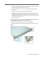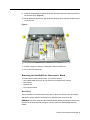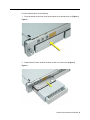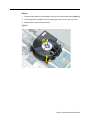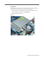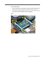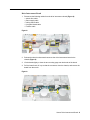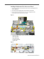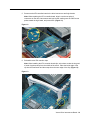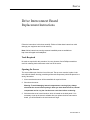
1
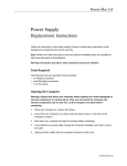
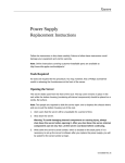
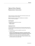
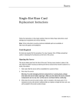
Xserve Drive Interconnect Board Replacement Instructions Follow the instructions in this sheet carefully. Failure to follow these instructions could damage your equipment and void its warranty. Note: Online instructions covering customer-installable parts are available at http://www.info.apple.com/installparts/. Tools Required No tools are required for this procedure. You may, however, find a Phillips screwdriver useful in releasing the thumbscrews at the front of the server. Opening the Server The server slides open from the front of the rack. The top cover remains in place in the rack while the bottom housing (containing all internal components) should be placed on a sturdy, flat surface. 1. Alert users that the server will be unavailable for a period of time. 2. Shut down the server. Warning: To avoid damaging internal components or causing injury, always shut down the server before opening it. After you shut down the server, internal components can be very hot. Let the server cool down before continuing. 3. Write down the server’s serial number, which is located on the back panel. If it is necessary to set up the server’s software after you replace the drive interconnect board, you will be asked for the serial number at login. 073-0673 Rev. C 4. If the server is in the locked position (the yellow security LED on the front panel is on), use the Allen key that came with the server to unlock it. 5. If the cable management arm is not in use, unplug all external cables except the power cord. 6. Touch the server’s metal case to discharge any static electricity. Important: Always ground yourself by touching the server’s case before you touch any parts or install any components inside the server. To avoid static electricity building back up in your body, do not walk around the room until you have completed your work and closed the computer. 7. Unplug the power cord. Warning: The power supply in the server is a high-voltage component and should not be opened for any reason, even when the server is off. 8. Release the two thumbscrews at the front of the server. (Figure 1) Note: The thumbscrews are captive and do not separate from the bottom housing. Figure 1 Xserve Drive Interconnect Board - 2 9. Grasp the thumbscrews and slide the bottom housing forward part way to expose the two chassis levers. (Figure 2) 10. While depressing both levers, pull the bottom housing all the way forward and remove it from the rack. Figure 2 11. Place the bottom housing on a sturdy, flat surface and ESD mat. 12. Put on the ESD wrist strap. Removing the Installed Drive Interconnect Board To remove the drive interconnect board, you must first remove: • any installed hard drives (you do not need to remove blank drive carriers) • both blowers • heatsink duct • ATA controller board Hard Drives Xserve includes four hard drive bays at the front of the server. Drives come as modules attached to carriers; they are removed from or installed in the server as a unit. WARNING: The server must be in the unlocked position before you attempt to remove any drives. If the drives are locked, pulling on a drive to remove it could damage the drive handle. Xserve Drive Interconnect Board - 3 For each installed drive, do the following: 1. Press the handle on the front of the drive module so the handle pops out. (Figure 3) Figure 3 2. Grasp the drive handle, and pull the drive module out of the server. (Figure 4) Figure 4 Xserve Drive Interconnect Board - 4 Blowers 1. Disconnect the cable for the right blower from the drive interconnect board. (Figure 5) 2. Lift the right blower straight up off its mounting pegs and remove it from the server. 3. Repeat steps 1 and 2 for the left blower. Figure 5 Xserve Drive Interconnect Board - 5 Heatsink Duct Note: There are two versions of Xserve. If your version does not include a plastic duct over the heatsink, skip to “ATA Controller Board” on the following page. 1. Release the latch on the heatsink duct from its slot, slide the duct away from the blower, and lift the end of the duct as shown. (Figure 6) 2. Remove the duct from the server. Figure 6 Xserve Drive Interconnect Board - 6 ATA Controller Board 1. Press in on both ends of the clip securing the right side of the ATA controller board and remove the clip from the server. Repeat for the clip on the left side of the board. 2. Lift the ATA controller board straight up to disconnect it from the drive interconnect and logic boards and remove the board from the server. (Figure 7) Figure 7 Xserve Drive Interconnect Board - 7 Drive Interconnect Board 1. Disconnect the following cables from the drive interconnect board: (Figure 8) • optical drive cable • power supply cable • locking switch cable • front panel board cable • FireWire cable Figure 8 2. Release the three thumbscrews that secure the drive interconnect board to the chassis.(Figure 9) 3. Lift the board slightly to clear the two mounting pegs near both ends of the board. 4. Pull the board back, tilt it up so that the connectors clear the chassis, and remove the board from the server. Figure 9 Xserve Drive Interconnect Board - 8 Installing the Replacement Drive Interconnect Board 1. Install the replacement drive interconnect board on the two mounting pegs in the chassis. (Figure 10) 2. Check that the board engages with the three brackets on the chassis. 3. Press the board firmly toward the front of the server, and tighten the three thumbscrews that secure the board to the chassis. Figure 10 4. Connect the following cables to the drive interconnect board: (Figure 11) • optical drive cable • power supply cable • locking switch cable • front panel board cable • FireWire cable Figure 11 Xserve Drive Interconnect Board - 9 5. Reconnect the ATA controller board to the drive interconnect and logic boards. Note: When replacing the ATA controller board, align it over the two pairs of connectors on the drive interconnect and logic boards, making sure the “MLB” arrow points toward the logic board, and press down. (Figure 12) Figure 12 6. Reinstall the two ATA controller clips. Note: When installing the ATA controller board clips, orient them so that the long end of each clip points away from the middle of the server. Place the inside edge of the clip into the small notch and then snap down the outer edge of the clip. (Figure 13) Figure 13 Xserve Drive Interconnect Board - 10 7. If you removed it earlier, replace the heatsink duct on the heatsink. 8. Reinstall the blowers. 9. Reinstall the hard drives. Closing the Server 1. Carefully slide the bottom housing back into the rack. 2. Tighten the front thumbscrews to secure it. Warning: Never turn on the server unless all of its internal and external parts are in place and it is closed. Operating the server when it is open or missing parts can damage it or cause injury. Apple Computer, Inc. © 2003 Apple Computer, Inc. All rights reserved. This document is protected under U.S. Copyright Law and International Treaties, and no part of this document may be reproduced in any form without written permission from Apple. Apple is not responsible for typographical, printing, or inadvertent errors. Apple Computer, Inc. 1 Infinite Loop Cupertino, CA 95014-2084 USA + 1 408 996 1010 http://www.apple.com Apple, the Apple logo, Mac, Macintosh, and the Mac logo are trademarks of Apple Computer, Inc., registered in the U.S. and other countries. Xserve is a trademark of Apple Computer, Inc. Xserve Drive Interconnect Board - 11