1
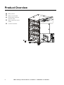
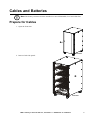
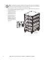
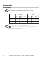
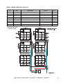
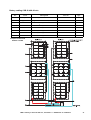
Battery Installation MGE™ Galaxy™ 300 10-40 kVA 380/400/415 V 10-40 kVA Contents Overview .......................................................................... 1 IMPORTANT SAFETY INSTRUCTIONS - SAVE THESE INSTRUCTIONS . . . . . . . . . . . . . . . . . . . . . . . . . . . . . . 1 Product Overview............................................................ 2 Cables and Batteries....................................................... 3 Prepare for Cables . . . . . . . . . . . . . . . . . . . . . . . . . . . . . . . . . . . . . . . . 3 Battery enclosure with pre-installed batteries . . . . . . . . . . . . . . . . . 4 Battery enclosure without pre-installed batteries . . . . . . . . . . . . . . 5 Connect Communication Cables between the UPS and Battery Enclosure . . . . . . . . . . . . . . . . . . . . . . . . . . . . . . . . . . . . . . . . . 7 External battery temperature (ATIZ) and external battery breaker signal . . . . . . . . . . . . . . . . . . . . . . . . . . . . . . . . . . . . . . . . . . . . . . . . . . 7 Connect the Battery Cables between the UPS and Battery Enclosure . . . . . . . . . . . . . . . . . . . . . . . . . . . . . . . . . . . . . . . . . 8 BAT+, BAT-, and N . . . . . . . . . . . . . . . . . . . . . . . . . . . . . . . . . . . . . . . 8 Connect an XR Battery Enclosure to a running UPS. . . . . . . . . . . . 10 Replace the Batteries . . . . . . . . . . . . . . . . . . . . . . . . . . . . . . . . . . . . . 12 Specifications................................................................ 13 Battery Output . . . . . . . . . . . . . . . . . . . . . . . . . . . . . . . . . . . . . . . . . . . 13 Recommended Cable Sizes . . . . . . . . . . . . . . . . . . . . . . . . . . . . . . . . 13 Recommended Bolt and Lug Size . . . . . . . . . . . . . . . . . . . . . . . . . . . 14 Torque specifications . . . . . . . . . . . . . . . . . . . . . . . . . . . . . . . . . . . . 14 MGE™ Galaxy™ 300 10-40 kVA 3:3 - 380/400/415 V, 10-30 kVA 3:1 - 380/400/415 V Installation i Checklist......................................................................... 15 Appendix ........................................................................ 16 One-line diagrams . . . . . . . . . . . . . . . . . . . . . . . . . . . . . . . . . . . . . . . 16 Battery cabling YUASA 15 kVA 60 min. . . . . . . . . . . . . . . . . . . . . . . 17 Battery cabling YUASA 20/30 kVA 60 min. . . . . . . . . . . . . . . . . . . . 18 Battery cabling YUASA 40 kVA 60 min. . . . . . . . . . . . . . . . . . . . . . . 19 Battery cabling CSB 15 kVA 60 min. . . . . . . . . . . . . . . . . . . . . . . . . 20 Battery cabling CSB 30 kVA 60 min. . . . . . . . . . . . . . . . . . . . . . . . . 21 Battery cabling CSB 40 kVA 60 min. . . . . . . . . . . . . . . . . . . . . . . . . 22 ii MGE™ Galaxy™ 300 10-40 kVA 3:3 - 380/400/415 V, 10-30 kVA 3:1 - 380/400/415 V Installation Overview IMPORTANT SAFETY INSTRUCTIONS - SAVE THESE INSTRUCTIONS Warning: ALL safety instructions in the Safety Sheet (990-3620) must be read, understood and followed when installing the UPS and XR Battery enclsoure(s). Failure to do so could result in equipment damage, serious injury, or death. Warning: The maximum storage time of the UPS is limited to six months due to the need of recharging the integrated batteries. If the UPS remains de-energised for a long period, we recommend that you energise the UPS for a period of 24 hours, at least once every month. This charges the battery, thus avoiding possible irreversible damage. Caution: All electrical power and power control wiring must be installed by a qualified electrician, and must comply with local and national regulations for maximum power rating. MGE™ Galaxy™ 300 10-40 kVA 3:3, 10-30 kVA 3:1 - 380/400/415 V Installation 1 Product Overview Battery shelves Battery circuit breaker Ground cable connection (from the UPS) Battery temperature sensor (ATIZ) Connection terminal Front view 2 MGE™ Galaxy™ 300 10-40 kVA 3:3, 10-30 kVA 3:1 - 380/400/415 V Installation Cables and Batteries Note: The battery enclosure must be installed on a non-inflammable, level and solid floor. Prepare for Cables 1. Open the front door. Front view 2. Remove both side panels. Front view MGE™ Galaxy™ 300 10-40 kVA 3:3, 10-30 kVA 3:1 - 380/400/415 V Installation 3 Battery enclosure with pre-installed batteries Warning: Remove all cardboard used to protect the batteries during transport. Make sure that cables and copper bars are separated. Note: A maximum of two battery enclosures can be connected to the UPS (one XR Battery enclosure with a circuit breaker plus one enclosure without a circuit breaker) by a batch cable between the UPS and the circuit breaker in the battery enclosure. 1. Remove the left and right plastic cover from the battery breaker by removing the two screws fastening each plastic cover. Front view 4 MGE™ Galaxy™ 300 10-40 kVA 3:3, 10-30 kVA 3:1 - 380/400/415 V Installation 2. Connect the batteries to the battery breaker by running the cables from the battery breaker to each shelve. Note! Make sure to run the cables in this order. + N - Front view Battery enclosure without pre-installed batteries Warning: APC by Schneider is not responsible for the wiring of external non-APC batteries. Warning: Remove all cardboard used to protect the batteries during transport. Make sure that cables and copper bars are separated. Note: Before the installation of batteries, you must select and follow the diagram under “Appendix” on page 16 which applies to your configuration. Note: The maximum weight of each battery shelf is 155 kg. Note: A maximum of four battery shelves can be installed. MGE™ Galaxy™ 300 10-40 kVA 3:3, 10-30 kVA 3:1 - 380/400/415 V Installation 5 Note: A maximum of two battery enclosures can be connected to the UPS (one XR Battery enclosure with a circuit breaker plus one enclosure without a circuit breaker) by a batch cable between the UPS and the circuit breaker in the battery enclosure. 1. Insert the batteries on the shelves starting from the bottom according to the relevant diagram for your configuration under “Appendix” on page 16. 2. Connect the batteries according to the chosen configuration diagram. 3. Install a battery breaker. 4. Connect the batteries to the battery breaker by running the cables from the battery breaker to each shelve. Note! Make sure to run the cables in this order. + N - Front view 6 MGE™ Galaxy™ 300 10-40 kVA 3:3, 10-30 kVA 3:1 - 380/400/415 V Installation Connect Communication Cables between the UPS and Battery Enclosure External battery temperature (ATIZ) and external battery breaker signal Note: The ATIZ cable is for external battery temperature detection signal (cable is preinstalled). Note: The battery cable is for external battery breaker signal (cable is pre-installed). Note: The connection of communication cables is only applicable between the UPS and XR1. For the connection of XR2, follow step 2 only. 1. Run the combined battery breaker and ATIZ signal cable from the XR connection terminal as shown. Note! See the UPS installation manual for information on where to connect the other end of the cable(s) to the UPS. Battery enclosure 2. Run the four cables from the XR connection terminal to the XR battery breaker (see the below table for cable description). Battery breaker signal cable to the UPS Front view To the UPS Cable description (step 2) Cable color Cable label Description Yellow QB OF-11 CB contactor signal White QB OF-14 CB contactor signal Red QB OF-D4 +12 V power supply Black QB OF-D1 -12 V power supply MGE™ Galaxy™ 300 10-40 kVA 3:3, 10-30 kVA 3:1 - 380/400/415 V Installation 7 Connect the Battery Cables between the UPS and Battery Enclosure Warning: This procedure describes how to connect the initial battery cables between the UPS and XR before start-up. If the UPS is up running, see “Connect an XR Battery Enclosure to a running UPS” on page 10. BAT+, BAT-, and N 1. Run the ground cable up through the bottom front hole of the XR and connect it to the busbar. 2. Run the BAT+, N, and BATcables up through the bottom front hole. Battery enclosure 3. Attach the cables to the right side of the battery breaker. 4. Reinstall the side panels. + N - Cables to/from the UPS Front view 8 MGE™ Galaxy™ 300 10-40 kVA 3:3, 10-30 kVA 3:1 - 380/400/415 V Installation + N - 10-40 + , N, kVA 3: 3 Batter y Rear view of the UPS + , N, 10- 15 kVA 3: Battery 1 20-30 + , N, kVA 3: 1 Batter y 5. Connect the battery cables to the battery terminals in the UPS. See the UPS installation manual for information on how to remove the I/O sheet metal cover. 6. Re-install the UPS covers. See the UPS installation manual for more information. MGE™ Galaxy™ 300 10-40 kVA 3:3, 10-30 kVA 3:1 - 380/400/415 V Installation 9 Connect an XR Battery Enclosure to a running UPS Warning: Before connecting an XR battery enclosure, ALL safety instructions in the Safety Sheet (990-3620) must be read, understood and followed. Failure to do so could result in equipment damage, serious injury, or death. Note: This procedure describes how to connect an XR battery enclosure to a UPS running in normal operation. Note: A maximum of two battery enclosures can be connected to the UPS (one XR Battery enclosure with a circuit breaker plus one enclosure without a circuit breaker) by a batch cable between the UPS and the circuit breaker in the battery enclosure. Note: Before carrying out the below procedure, make sure that the UPS is running in normal operation with no internal UPS faults displayed. In normal operation all breakers must be in the ON (closed) position except for the maintenance bypass breaker which must be in the OFF (opened) position. 1. Turn the UPS into maintenance bypass operation: a. Turn the static bypass breaker (QM2) to the ON (closed) position. b. Turn the maintenance bypass breaker (Q3BP) to the ON (closed) position. c. Turn the static bypass breaker (QM2) to the OFF (opened) position. d. Turn the output breaker (QOP) to the OFF (opened) position. 2. Isolate the batteries by turning the UPS battery breaker (QB) (and the existing XR battery breaker (QFB), if present) to the OFF (opened) position. 3. Remove all internal batteries in the UPS enclosure. 4. Prepare for cables. See “Prepare for Cables” on page 3. 5. Install the batteries. See “Battery enclosure with pre-installed batteries” on page 4 or “Battery enclosure without pre-installed batteries” on page 5. 6. Connect the communication cables between the UPS and the XR. See “Connect Communication Cables between the UPS and Battery Enclosure” on page 7. 7. Connect the XR Battery enclosure according to the relevant, electrical diagram under “Appendix” on page 16, and according to the chapter “Connect the Battery Cables between the UPS and Battery Enclosure” on page 8. 8. Verify the battery wiring as described under “Battery enclosure with pre-installed batteries” on page 4 or “Battery enclosure without pre-installed batteries” on page 5 10 MGE™ Galaxy™ 300 10-40 kVA 3:3, 10-30 kVA 3:1 - 380/400/415 V Installation Electrical Hazard: Check the DC voltages with a DC voltage multimeter versus the battery voltage before continuing. 7. Turn the XR battery breaker (QFB) to the ON (closed) position. 8. Turn the UPS back into normal operation: a. Turn the static bypass breaker (QM2) to the ON (closed) position. b. Turn the output breaker (QOP) to the ON (closed) position. c. Turn the maintenance bypass breaker (Q3BP) to the OFF (opened) position. d. Turn the UPS battery breaker (QB) to the ON (closed) position. e. Turn the input breaker (QM1) to the ON (closed) position. 9. Check the LEDs to see if the UPS is running in normal operation: • PFC LED: green • INVERTER LED: green • LOAD LED: green • LOAD PROTECTED LED: green • Other LEDs: OFF MGE™ Galaxy™ 300 10-40 kVA 3:3, 10-30 kVA 3:1 - 380/400/415 V Installation 11 Replace the Batteries Warning: Before battery replacement, ALL safety instructions in the Safety Sheet (9903620) must be read, understood and followed. Failure to do so could result in equipment damage, serious injury, or death. Caution: Batteries must be replaced by qualified electricians only. Note: For the replacement of batteries, please refer to the relevant diagram for your configuration under “Appendix” on page 16. Note: Before replacing batteries, make sure that the UPS is running in normal operation with no internal UPS faults displayed. In normal operation all breakers must be in the ON (closed) position except for the maintenance bypass breaker which must be in the OFF (opened) position. Note: Replacing batteries in the UPS and in the XR enclosure(s) requires that the UPS is turned into maintenance bypass operation and that the batteries are disconnected. Follow the procedure described under “Connect an XR Battery Enclosure to a running UPS” on page 10. 12 MGE™ Galaxy™ 300 10-40 kVA 3:3, 10-30 kVA 3:1 - 380/400/415 V Installation Specifications Battery Output Battery Description Nom voltage (V) 12 v/block INom discharge1 See the battery input table in the UPS installation manual 990-3618 IMax discharge2 See the battery input table in the UPS installation guide 990-3618 End Voltage 9.9 v/block 1 Nominal battery discharge current based on rated load and nominal battery voltage. 2 Maximum battery discharge current based on rated load at the end of the discharge. Recommended Cable Sizes Caution: All wiring must comply with all applicable national and/or electrical codes. Note: AC cable sizes are determined for: - the TNS system for copper, single-core cables, type U1000 R02V, 100 m long with a line voltage drop <3%, installed on perforated cable trays, XLPE-type insulation, single-layer trefoil formation, THDI between 15% and 33%, 35°C, at 400 V, grouped in four touching cables. Battery cable sizes are determined for: - copper, single-core cables, type U1000 R02V, maximum length 25 m with a line voltage drop <1%. 3:3 10 kVA 15 20 3:1 30 40 10 15 20 30 min max min max min max min max min max min max min max min max min max Mains input (mm²) 10 35 10 35 10 35 16 35 25 35 10 35 10 35 10 90 16 90 AC output (mm²) 10 35 10 35 10 35 16 35 25 35 10 35 25 35 35 90 70 90 Battery (mm²) 10 35 10 35 16 35 25 35 35 35 10 35 10 35 16 25 25 35 Bypass (mm²) 10 35 10 35 10 35 16 35 35 35 10 35 25 34 35 90 70 90 MGE™ Galaxy™ 300 10-40 kVA 3:3, 10-30 kVA 3:1 - 380/400/415 V Installation 13 Recommended Bolt and Lug Size Torque specifications Battery Terminal Bolt size Torque CSB 910-0631 910-0633 clip M6 5.4 NM (max 8.2 NM) YUASA 14 912-0001 M5 2.5 NM (max 6 NM) 910-0632 M6 4.8 NM (max 6 NM) MGE™ Galaxy™ 300 10-40 kVA 3:3, 10-30 kVA 3:1 - 380/400/415 V Installation Checklist Make sure that all cardboard and strappings have been removed. Check that the power wiring is torqued as described in the torque specification table above. Verify clockwise phase-rotation (BAT+, N and BAT-) and make sure that a neutral connection is present. Leave a wiring diagram on site for service personnel. Re-install all wiring access panels on the UPS. For any optional equipment, refer to product-specific manuals. Make sure that all battery breakers (on the UPS unit and XR Battery Enclosure(s) if applicable) are in the OFF (opened) position. MGE™ Galaxy™ 300 10-40 kVA 3:3, 10-30 kVA 3:1 - 380/400/415 V Installation 15 Appendix One-line diagrams Note: Use the below table as a help to find the diagram that fits your system. YUASA CSB 15 KVA 60 min 20 KVA/ 30 KVA 60 min 40 KVA 60 min 15 KVA 60 min 30 KVA 60 min 40 KVA 60 min Part no. 885-4766B 885-4767B 885-4770B 885-4769A 885-4773A 885-4774A Name G3HTBAT1 G3HTBAT2 G3HTBAT3 G3HTBAT1 G3HTBAT2 G3HTBAT3 Battery enclosure qty. 1 2 2 1 2 2 Note: - marked cables are assembled by the manufacturer. - marked cables are assembled on site by APC by Schneider or a sub contractor. Black diagram lines represent white cables. 16 MGE™ Galaxy™ 300 10-40 kVA 3:3, 10-30 kVA 3:1 - 380/400/415 V Installation Battery cabling YUASA 15 kVA 60 min. No. Item Description Part no. Qty. A Battery Yuasa battery SWL 1100 912-0001 30 B Copper bar 70*25*2 880-2755 20 mm2 C Power cable Wire 16 Ivory 380 mm 0W5032 3 D Power cable Wire 16 mm2 Ivory 640mm 0W5035 3 0W5034 2 mm2 E Power cable Wire Assy 16 F Power cable Wire Assy 16 mm2 red 900 mm CB+ 0W4982 1 G Power cable Wire Assy 1 string CBN 0W4989 1 0W4986 1 H Power cable Wire Assy 16 mm2 Ivory 1200 mm White 900 mm CB- *Torque for screws to link batteries is 2.5 Nm MGE™ Galaxy™ 300 10-40 kVA 3:3, 10-30 kVA 3:1 - 380/400/415 V Installation 17 Battery cabling YUASA 20/30 kVA 60 min. No. Item Description Part no. A Battery Yuasa battery SWL 1850 910-0632 30 B Copper bar 110*25*3 880-2754 14 2 C Power cable Wire 16 mm Ivory 380 mm 0W5032 4 D Power cable Wire 16 mm2 Ivory 640mm 0W5035 6 E Power cable Wire Assy 16 mm2 Ivory 1200 mm 0W5034 4 mm2 red 1800 mm CB+ 0W4983 1 0W4991 1 0W4986 1 F Power cable Wire Assy 16 G Power cable Wire Assy 1 string CBN H Power cable 2 Wire Assy 16 mm White 900 mm CB- *Torque for screws to link batteries is 4.8 Nm 18 Qty. MGE™ Galaxy™ 300 10-40 kVA 3:3, 10-30 kVA 3:1 - 380/400/415 V Installation Battery cabling YUASA 40 kVA 60 min. No. Item Description Part no. Qty. A Battery Yuasa battery SWL 1100 912-0001 64 B Copper bar 70*25*2 880-2755 40 mm2 C Power cable Wire 16 Ivory 380 mm 0W5032 4 D Power cable Wire 16 mm2 Ivory 640mm 0W5035 12 0W5034 4 mm2 E Power cable Wire Assy 16 F Power cable Wire Assy 2 strings CB+ 0W4984 1 G Power cable Wire Assy 2 strings CBN 0W4992 1 H Power cable Wire Assy 2 strings CB- 0W4987 1 Ivory 1200 mm *Torque for screws to link batteries is 2.5 Nm MGE™ Galaxy™ 300 10-40 kVA 3:3, 10-30 kVA 3:1 - 380/400/415 V Installation 19 Battery cabling CSB 15 kVA 60 min. No. 20 Item Description Part no. Qty. A Battery CSB battery GP12120 910-0631 90 B Power cable Wire 10 BLK 120 mm 0W4946 72 C Power cable Wire Awg 10 BLK 520 mm 0W4969 6 D Power cable Wire Awg 10 BLK 640 mm 0W4971 6 E Power cable Wire Assy 3 strings CB+ 0W4973 1 F Power cable Wire Assy 3 strings CBn 0W4981 1 G Power cable Wire Assy 3 strings CB- 0W4976 1 MGE™ Galaxy™ 300 10-40 kVA 3:3, 10-30 kVA 3:1 - 380/400/415 V Installation Battery cabling CSB 30 kVA 60 min. No. Item Description Part no. Qty. A Battery CSB battery GP12340 910-0633 64 B Copper bar Copper bar CU-ETP Battery GP12340 880-6019 36 16mm2 C Power cable Wire Ivory 520 mm 0W5033 12 D Power cable Wire 16mm2 Ivory 640 mm 0W5035 8 0W5034 4 16mm2 Ivory E Power cable Wire F Power cable Wire Assy 2 strings CB+ 0W4984 1 G Power cable Wire Assy 2 strings CBn 0W4992 1 H Power cable Wire Assy 2 strings CB- 0W4987 1 1200 mm *Torque for screws to link batteries is 5.4 Nm MGE™ Galaxy™ 300 10-40 kVA 3:3, 10-30 kVA 3:1 - 380/400/415 V Installation 21 Battery cabling CSB 40 kVA 60 min. No. Item Description Part no. A Battery CSB battery GP12340 910-0633 90 B Copper bar Copper bar CU-ETP Battery GP12340 880-6019 60 mm2 C Power cable Wire 16 Ivory 520mm 0W5033 12 D Power cable Wire 16 mm2 Ivory 640 mm 0W5035 12 E Power cable Wire Assy 3 strings CB+ 0W4985 1 F Power cable Wire Assy 3 strings CBn 0W4993 1 G Power cable Wire Assy 3 strings CB- 0W4988 1 *Torque for screws to link batteries is 5.4 Nm 22 Qty. MGE™ Galaxy™ 300 10-40 kVA 3:3, 10-30 kVA 3:1 - 380/400/415 V Installation APC Worldwide Customer Support Customer support for this or any other APC product is available at no charge in any of the following ways: • Visit the APC Web site to access documents in the APC Knowledge Base and to submit customer support requests. – www.apc.com (Corporate Headquarters) Connect to localized APC Web sites for specific countries, each of which provides customer support information. – www.apc.com/support/ Global support searching APC Knowledge Base and using e-support. • Contact the APC Customer Support Center by telephone or e-mail. – Local, country-specific centers: go to www.apc.com/support/contact for contact information. For information on how to obtain local customer support, contact the APC representative or other distributors from whom you purchased your APC product. Entire contents copyright 2010 American Power Conversion Corporation. All rights reserved. Reproduction in whole or in part without permission is prohibited. APC, the APC logo, and TRADEMARK NAMES are trademarks of American Power Conversion Corporation. All other trademarks, product names, and corporate names are the property of their respective owners and are used for informational purposes only. 990-3617-001 *990-3617-001* 6/2010