1
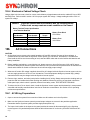
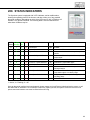
Installation Instructions
and
User Manual
For
Inverter
Power
Systems
400 to 2100 VA
READ AND FOLLOW ALL SAFETY
INSTRUCTIONS
IMPORTANT SAFEGUARDS
When using electrical equipment, you should always follow basic safety precautions,
including the following:
1. Read and follow all safety instructions.
2. Do not install the Synchron system outdoors.
3. Do not install near gas or electric heaters or in other high-temperature locations.
4. Use caution when servicing batteries. Battery acid can cause burns to skin and
eyes. If acid is spilled on skin or in the eyes, flush with fresh water and contact a physician immediately.
5. Equipment should be mounted in locations where it will not be readily subjected to tampering by unauthorized personnel.
6. The use of accessory equipment not recommended by the manufacturer may
cause an unsafe condition and may void the warranty.
7. Do not use this equipment for other than intended use.
8. All servicing of this equipment must be performed by qualified service personnel.
SAVE THESE INSTRUCTIONS
IMPORTANT SAFETY INSTRUCTIONS
The installation and use of this product must comply with all national, federal, state,
municipal, or local codes that apply.
For technical assistance, contact Dual-Lite's Systems Technical Support
Center at 1-800-848-6439.
Technicians are available during normal working hours (EST).
2
Table of Contents
Section 100 System Installation Instructions
Description
101.
Page
Unit Specifications......................................................................................................................................... 4
102.
Receiving, Moving and Storing Systems and Batteries............................................................................. 5
102.1 Shipping Damage........................................................................................................................ 5
102.2 Moving Units and Batteries.......................................................................................................... 5
102.3 Temporary Storage of Units and Batteries................................................................................... 5
103.
Installation Requirements............................................................................................................................. 6
103.1 Operating Environment................................................................................................................ 6
103.2 High Altitude Operation................................................................................................................ 6
104.
Cabinet Mounting (Physical)......................................................................................................................... 7
105.
Battery Installation and Connection.......................................................................................................... 8-9
105.1 Tools............................................................................................................................................ 8
105.2 Installation Considerations.......................................................................................................... 9
105.3 Battery Installation Procedure..................................................................................................... 9
105.4 Electronics Cabinet Voltage Check........................................................................................... 10
106.
AC Connections...................................................................................................................................... 10-11
106.1 AC Wiring Preparations............................................................................................................. 10
106.2 AC Input and AC Output Connections........................................................................................11
107.
Final Installation Checklist...........................................................................................................................11
108.
System Start-Up Procedure........................................................................................................................ 12
109.
System Verification...................................................................................................................................... 12
Section 200 User Manual
Description
..........................................................................................................................................................Page
200.Status Indicators.......................................................................................................................................... 13
Section 300 Maintenance, Warranty and Technical Support
300.Maintenance............................................................................................................................................. 14-16
300.1 Safe Shut Down Procedure....................................................................................................... 14
300.2 Routine System Maintenance.................................................................................................... 14
300.3 Manual Routine Inverter Tests................................................................................................... 14
300.4 Battery Maintenance and Replacement............................................................................... 15-16
301.
Warranty Information................................................................................................................................... 17
302.
Technical Service and Support................................................................................................................... 17
3
Section 100 System Installation Instructions
101. Specifications
Input
• Input voltage: 120 or 277VAC.
• Synchronizing slew rate: 1 Hz per second nominal
• Input surge protection: Meets ANSI 62.41 and UL 924
Output
• Output voltage: 120 or 277VAC
• Output regulation: (static) ±5% based on a 0% - 100% resistive load
• Minimum loading: none required
• Output distortion: Less than 5% THD linear load
• Load power factor: .75 lag to .8 lead
• Output frequency: Normally, synchronized to utility,
+.05 Hz during emergency
• Overload: 115% momentary
• Time to transfer to inverter after a utility power failure: No break
Battery
• Battery charger: Fully automatic and temperature compensated with internal diagnostic indicators
• Recharge time: 60 hours
• Battery protection: Automatic low-battery voltage disconnect.
Automatic restart upon utility return
• Battery switch: Also used as battery isolator
• Standard battery: Sealed lead-calcium: 10-year life
• Battery voltage: 36, 72 or 96VDC (system dependent)
• Runtimes: 90 minutes standard.
• Operating temperature: 20°C to 30°C (68°F to 86°F)
• Relative humidity: 95% non-condensing
Note: Battery performance rated at 25°C (77°F)
Table 1.
Synchron Sizing Chart
VA/Watts
4005257501000
1500
2100
Power Factor Range
.75 Lag to .8 Lead
Input/Output Voltage
120/120 or 277/277
AC Input Circuit Breaker Rating - 7A/3A 10A/5A
13A/6A 20A/8A25A/10A
6A/3A
120/277VAC
Charger Size System DC Voltage
Cabinet Size
BTU/Hour - Line/Inverter
Weight [lbs. (kg) - including batteries]
4
2 Amps
363672727296
22"W x 23"H x 10"D
32"W x 36.5"H x 12"D
(55.9cm W x 58.4cm H x 25.4cm D)
(81.3cm W x 92.7cm H x 30.5cm D)
70/260
92/341
131/382
175/510
143 (65.1)
173 (78.8)
281 (128)
346 (157.6)
263/765
368/886
400 (182.2) 480 (218.7)
102. Receiving, Moving and Storing Systems and Batteries
102.1 Shipping Damage
Synchron inverter systems and batteries are shipped separately.
Carefully inspect all cartons upon receipt for evidence of shipping damage.
Notify carrier immediately of leaking or damaged cartons for possible concealed damage.
102.2 Moving Units and Batteries
CAUTION: Batteries and Synchron Electronics cabinets are very heavy. Proper equipment should
always be used to move batteries and units to avoid damage and personal injury.
WARNINGS:
• ALWAYS WEAR PERSONAL EYE PROTECTION WHEN WORKING WITH BATTERIES - SEE PAGE 10
• Batteries contain liquid caustic or acid electrolytes which CAN CAUSE SEVERE BURNS.
Care must be taken when moving batteries to avoid tipping and spillage of electrolyte material.
In case of accidental spill.
FIRST AID:
• EYES: Flush immediately with flowing water for at least 15 minutes. Seek medical attention.
• EXTERNAL: Flush immediately with water. Seek medical attention.
102.3 Temporary Storage of Units and Batteries
For temporary storage of Synchron inverter systems and batteries prior to installation, select a clean, cool, dry
location with normal ventilation for human habitation and level floors.
CAUTION: Batteries and Synchron Electronics cabinets are very heavy. Check to assure that the floor in the
temporary storage area is capable of safely bearing the load.
IMPORTANT:
Lengthy storage of batteries will cause irreversible damage to the cells.
Failure to connect Synchron inverter system batteries to an energized charging circuit within 90 days from
the date of shipment will void the battery warranty.
Storage Temperature:
Store all batteries at 10° to +30° C (50° to +86° F). Batteries will have a longer shelf life if stored at 10° to +30° C (50°
to +86° F). The Synchron electronics and battery cabinets may be stored at -20° to +60° C (-4° to +140° F).
Ventilation: The air around the unit must be clean, dust-free, and free of corrosive chemicals or other contaminants. Do not place
the Synchron inverter system or batteries in a sealed room or container.
DANGER: EXPLOSIVE - CAN CAUSE BLINDNESS OR OTHER SEVERE INJURIES.
Every type of battery can produce hydrogen gas, even sealed, maintenance-free batteries. The gas is vented through
the vent caps and into the air.
Do not allow smoking, sparks, or flames in battery storage location because hydrogen is concentrated under
the vent cap of each cell of the battery. Hydrogen is highly explosive, and is hard to detect because it is
colorless, odorless, and lighter than air.
5
103. Installation Requirements
103.1 Operating Environment
Install the Synchron inverter system in a clean, cool, dry place with normal ventilation for human habitation and level
floors.
CAUTION: Batteries and Synchron Electronics cabinets are very heavy. Check to assure
that the floor is capable of safely bearing the load.
Operating Temperature: Synchron inverter Systems are UL Listed for 20° to 30° C (+ 68° to +86° F) operation.
The Synchron Inverter System has a designed operating range of 0° to +40° C (+32° to +104° F) at up to 95%
relative humidity. Installation in environments at the temperature extremes of the designed operating range may effect
unit performance or reduce service life.
Battery performance and service life is maximized if the operating temperature is maintained at 25° C (77° F) .
Ventilation: The air around the unit must be clean, dust-free, and free of corrosive chemicals or other contaminants. Do not place
the Synchron inverter system or batteries in a sealed room or container.
Batteries:
The temperature should be near 25° C (77° F) for optimum battery performance.
Temperature Effect On Performance:
Batteries will be less efficient at temperatures below 18° C (65° F), and high temperatures will reduce battery life.
Typically, at 35° C (95° F), battery life will be half of what it would be at normal temperature of 25° C (77° F). At 45° C
(113° F), battery life will be one-fourth of normal.
WARNING: Every type of battery can produce hydrogen gas, even sealed, maintenance-free batteries. The gas is
vented through the vent caps and into the air, mainly when the unit is charging the batteries. The batteries produce the
most hydrogen when maximum voltage is present in fully charged batteries. The amount of current that the charger
supplies to the batteries (not the battery ampere-hour) determines how much hydrogen is produced.
Do not allow smoking, sparks, or flames in battery storage location because hydrogen is concentrated under
the vent cap of each cell of the battery. Hydrogen is highly explosive, and is hard to detect because it is
colorless, odorless, and lighter than air.
!
CAUTION
NEVER INSTALL BATTERIES IN A
SEALED ROOM OR ENCLOSURE
IMPORTANT:
Lengthy storage of batteries will cause irreversible damage to the cells.
Failure to connect Synchron inverter system batteries to an energized charging circuit
within 90 days from the date of shipment will void the battery warranty.
103.2 High Altitude Operation:
The maximum operating temperature drops 1° Celsius per 300 meters (2° F per 1000 feet) above sea level. Maximum
elevation is 3000 meters (10,000 feet).
6
104. Cabinet Mounting
The Synchron 400 and 525 VA models are supplied with two full length brackets for wall mounting; while the 750 VA
and up models are designed for floor mounting. These are also supplied with side mount stabilizing brackets to secure
the cabinet to the wall.
Dual-Lite supplies the hardware to attach the brackets to the cabinet. Necessary hardware to fasten the cabinet to the
wall is to be supplied by the installing contractor. Please refer to the following illustrations.
Fig. 1
400 and 525 VA units - Small cabinet
Install Wall Mounting Brackets To Both
Sides Of Cabinet
Fig. 2
750 to 2100 VA units - Large cabinet
Install Wall Mounting
Brackets To Both
Sides Of Cabinet
Once the cabinet is securely fastened to the wall, run and attach conduit using the provided knock outs on the top of
the unit. If you need additional entry points, please use a metal punch. Do not drill into the cabinet as metal filings can
cause short circuits and damage the equipment.
Be sure to follow all federal, state, and local codes as it pertains to emergency circuit raceways.
7
105. Battery Installation and Connection
Installing the Batteries and DC Wiring
Important Safety Precautions
The installer must take these precautions:
1. Wear protective clothing, eye-wear, rubber gloves and boots. Batteries contain corrosive acids or
caustic alkalis and toxic materials and can rupture or leak if mistreated. Remove rings and metal
wristwatches or other metal objects and jewelry. Don’t carry metal objects in pockets where the
objects can fall onto the batteries or into the Synchron inverter system.
2. Tools must have insulated handles so that they will not short battery terminals. Do not allow a tool to
short a battery terminal to another battery terminal or to the cabinet at any time. Do not lay tools or
metal parts on top of the batteries, and do not lay any objects where they could fall onto the batteries
or into the cabinet.
3. Install the batteries as shown on the battery wiring diagram provided in this manual or with the
battery cable kit. When connecting cables, never allow a cable to short across a battery’s terminals,
the string of batteries, or to the cabinet.
4. Align the cables on the battery terminals so that the cable lug will not contact any part of the cabinet
even if the battery is moved. Keep the cable away from any sharp metal edges.
5. Install the battery cables so they cannot be pinched by the Synchron inverter system cover/door.
6. Where conductors may be exposed to physical damage, protect conductors in accordance with NEC
requirements.
7. Full voltage and current are always present at the battery terminals. The batteries used in this
system can produce dangerous voltages, extremely high currents, and possible risk of electric
shock. Batteries may cause severe injury if the terminals are shorted together or to ground (earth).
Be extremely careful to avoid electric shock and burns caused by contacting battery terminals or
shorting terminals during battery installation. Do not touch uninsulated battery terminals.
8. A qualified electrician who is familiar with battery systems and required precautions must install and
service the batteries. Any battery used with this unit shall comply with the applicable requirements
for batteries in the standard for emergency lighting and power equipment, UL 924. Cabinets are
designed to be used with, and batteries must be replaced by identical cells or a Dual-Lite approved
equivalent. If using substitute batteries not supplied by Dual-Lite, the unit’s UL listing will be void,
and the equipment may fail to perform properly. The installation must conform to national and local
codes as well. Keep unauthorized personnel away from batteries.
105.1Tools
The following tools are required to install the system batteries. Other tools may be necessary if optional batteries
have been ordered.
CAUTION: Always use insulated tools for battery installation. Always torque to the manufacturer’s
recommendations.
• Socket Set
• Safety Equipment Required by Local Codes
• Slotted Screwdriver
• Torque Wrench Calibrated in Inch-pounds or Newton-meters
• Electrical Tape • Digital Volt-Ohm Meter
• Safety Glasses with Side Shields
8
105.2 Installation Considerations
This section explains how to install the Synchron system’s batteries, fuses, and cables. A qualified electrician who is
familiar with battery installations and applicable building and electrical codes should install the batteries.
105.3 Battery Installation Procedure
Battery Voltage:Select which wiring diagram to use from this table:
VA/Watts
400 525 750 100015002100
System DC Voltage
363672727296
Battery P/N
012093501209360120937012093593012368
93012368
Number of Batteries
336668
Battery Fuse Rating (Amps)
606060606060
Wiring Diagram Fig.
112223
IMPORTANT: Be careful to observe correct polarity on the battery terminals. Illustrations are given as a guide only,
polarity markings may vary from battery to battery.
Figure 1
Figure 2
36 Volt Battery Connection Diagram
72 Volt Battery Connection Diagram
400 and 525 VA Model
750, 1000 and 1500 VA Model
Figure 3
96 Volt Battery Connection Diagram
2100 VA Model
IMPORTANT
Once batteries have been wired as shown, the system's DC fuse
must be installed.
MAKE SURE THE DC BREAKER IS IN THE OFF
POSITION BEFORE PROCEEDING.
The DC fuse is shipped separately inside the cabinet and needs
to be installed in its fuse block holder located on the underside
of the electronics shelf. Use insulated tools to perform this
task, full battery voltage will be present at the fuse block.
DO NOT TURN ON THE DC BREAKER AT THIS
TIME AS SIGNIFICANT DAMAGE TO THE SYSTEM
WILL OCCUR.
See Section 108 for proper system start-up procedure.
9
105.4 Electronics Cabinet Voltage Check
Using a digital volt-ohm meter, check for correct nominal battery voltage between electronics cabinet DC Input NEG
and POS wires. Refer to table in section 105.3 for proper system DC voltage. Voltage reading should be ±10% of
system DC voltage.
Caution: Torque all connections in accordance with the following tables.
Failure to do so may create an unsafe condition or fire hazard.
Battery Terminal Torque Specifications
Lead-Calcium Batteries
Manufacturer'sDual-Lite
Part Number
Part NumberTorque
GP12260
0120937
2.2 ft.-lbs.
GP12340
0120935
6.0 ft-lbs.
GP12400
0120936
2.2 ft-lbs.
-
93012368
2.5 ft-lbs.
106. Battery Fuse Block
275 inch-lbs.
Battery Fuse
120 inch-lbs.
AC Connections
CAUTION
A. All Synchron inverter system units contain hazardous AC and DC voltages. Because of these voltages, a
qualified electrician must install the Synchron inverter system, AC line service, and batteries. The electrician
must install the AC line service according to local, state and NEC codes and must be familiar with batteries and
battery installation.
B. Before installing, maintaining, or servicing the unit, always remove or shut off all sources of AC and DC power
and shut off the Synchron inverter system. Disconnect AC line input at the service panel and turn off the Main DC
Switch and the Main AC Switch to make sure the unit will not supply output voltage.
C. Whenever AC and/or DC voltage is applied, there will be AC voltage inside the Synchron inverter system unit; the
unit can supply power from AC line or from its batteries. To avoid equipment damage or personal injury, always
assume that there may be voltage inside the Synchron inverter system.
D. Remove rings, watches, and other jewelry before installing the AC wiring. Always wear protective clothing and eye
protection and use insulated tools when working near batteries. Whenever servicing an energized unit with the
inside panel open, electric shock is possible; follow all local safety codes. TEST BEFORE TOUCHING!
E. To reduce the risk of fire or electric shock, install the Synchron inverter system and the batteries in a temperaturecontrolled and humidity-controlled indoor area free of conductive contaminants. See Section 103 for operating
environment specifications.
106.1 AC Wiring Preparations
1. Open or remove the system's front cover/door. Make sure all breakers are in the off position.
2. Make sure the Synchron inverter system input and output voltages are correct for the particular application.
Remember that the Synchron system provides single-phase power only.
3. The input circuit breaker in the input service panel provides the means for disconnecting AC to the Synchron
inverter system. Only authorized persons shall be able to disconnect AC to the unit. (See NEC 700-20 and 70021.)
10
CAUTION : To prevent electrical shock or equipment damage, for all units, the Main AC Switch, the Main
DC Switch, all output circuit breakers, and the AC input at the service panel are all off before making AC
connections to the Synchron inverter system.
4. If not previously done, remove knockouts for AC Input and AC Output in the top of the Synchron inverter system
(See Figure 1 in Section 104.1).
CAUTION: Do not drill the cabinet; drill filings may damage the unit and prevent it from operating. If
larger knockouts are needed, use a chassis punch to enlarge the appropriate knockout. Do not add
additional or unnecessary knockouts.
5. Install the input and output conduits.
6. Run the AC Input service conductors and AC Output conductors through separate conduits. Synchron inverter
system emergency output circuits shall be installed in dedicated conduit systems and not shared with other
electrical circuits as described in NEC 700-9(b).
106.2 AC Input and AC Output Connections
Make all AC input and output connections to the Synchron inverter system as indicated on the labels within the
cabinet. If system was supplied with internal output circuit breaker distribution option, make output wiring connections
directly to the circuit breakers.
Caution: Torque all connections in accordance with the following tables.
Failure to do so may create an unsafe condition or fire hazard.
Terminals
Terminal Width
Inches
mm
31/64 12.2
19/32 15.2
25/32
20
Torque
inch-lbs.
16
32
64
"C" Breakers
Rating
amps
10-30
Torque
inch-lbs.
25
107. Final Installation Checklist
Important: Before proceeding to the System Start-Up Procedure (Section 108) complete the Final
Installation Checklist below.
1. Insure the Synchron Inverter cabinet is securely fastened to a wall or other structure.
2. Insure that the input circuit breaker in the building service panel serving as the AC disconnect to the Synchron
system is in the OFF position.
3. Check for proper ground connections in the Synchron Inverter cabinet, the building service panel, and the external
load distribution panel.
4. Check for any loose wiring connections in the Synchron Inverter cabinet, the building service panel, and the
external load distribution panel.
5. Check that correct nominal battery voltage (36, 72 or 96VDC) is present in the Synchron Inverter cabinet between
the DC Input NEG and POS. Refer to Section 105.2 for proper system DC voltage.
6. On the Synchron Inverter insure that the Pre-charge Switch, the Main DC Switch, and the Main AC Switch are all
in the OFF position.
11
108. System Start-Up Procedure
IMPORTANT: The Synchron inverter system is a sophisticated electronic backup power supply. Care must
be taken to follow the steps below in their exact sequence. Failure to do so will result in erroneous alarm
messages and possible equipment failure.
CAUTION: Familiarize yourself with the shut down procedure in section 300.1 before proceeding with the
Start Up.
1. Make sure the front cover/door is installed and secured shut.
2. Turn on the input circuit breaker in the building service panel serving as the AC disconnect to the Synchron
system.
3. Open the front access panel so that the input/output circuit breakers within the Synchron unit are accessible.
4. Turn on all output circuit breakers located within the Synchron system, and/or in the external Load Distribution
Panel (if any).
5. Hold the Pre-charge Switch in the “ON” position for 30 seconds.
6. Release the Pre-charge Switch and immediately turn ON the Main DC Switch.
7. Turn on the Main AC switch.
8. After approximately five seconds, the system should turn on, the lighting loads should be energized, the front
panel green “AC-ON” and “LOAD” LEDs should illuminate.
109. System Verification
At this point, the connected load should be energized, the “Load” and “AC On” LEDs should be lit. Depending on
the state of charge of the batteries the inverter may or may not come on when the test switch is depressed. Allow a
24 hour charge period before testing the inverter system. If you need assistance, call Dual-Lite’s Technical Support
Center at 800-848-6439.
To simulate a power failure, simply press the test switch for a momentary test, or by opening the AC input circuit
breaker for a prolonged test. The inverter and the cooling fans (if any) will begin operating, the "AC On" LED will go off
and the "Load" LED will remain lit. All connected loads should be energized and operational, HID fixtures should not
"wink-out".
Allow the inverter to run for several minutes or until satisfied with its operation. Close the AC input breaker to end the
test and return the unit to standby mode.
Note: It will take a few seconds for the unit to re-synchronize with the input line. The inverter will turn off
when synchronization is achieved.
12
200. STATUS INDICATORS
The Synchron system is equipped with 3 LED indicators, and an audible alarm,
showing the operating mode of the inverter, and also to alert you of any possible
abnormal conditions. Depending on which of the LEDs are On, Off, or Blinking, will
indicate a very specific condition. The following table is used to illustrate as to
what these conditions may be:
AudibleAC Input/ Load AlarmSymptom
AlarmChargingOn
Mode Explanation
O
II
O
Normal Mode
LINE
O
OX
O
Inverter ON
INV
I OO
I
System Shutdown
OFF
X
OX
X
Inverter On - System Malfunction
INV
NORMAL
Load current < 5%
Shutdown - overload, heatsink overtemp, or battery failure possible
Load current < 5% and either probe failure or output breaker tripped
O
OI
O
Inverter On
INV
NORMAL
X
OI
X
Inverter On - System Malfunction
INV
Probe failure or output breaker tripped
O
IO
O
Line - No Load LINE
I
IO
I
System Shutdown
OFF
X
I
O
X
Line - System Malfunction
LINE
X
II
X
Line - System Malfunction
LINE
O
O
O
O
Off, no output
OFF
Load current < 5%
Shutdown - overload, heatsink overtemp, or severely discharged batteries
Load current < 5% and either charger or probe failure, output breaker tripped, or low battery voltage
Charger or probe failure, output breaker tripped, or low battery voltage
LVD or OFF
I = Active, X = Flashing, O = Off
Once an abnormal condition has been detected, please contact your local Factory Authorized service center, or call
800-848-6439 for assistance. Do not attempt to make any repairs yourself, the system is fed from more than one
power source and extreme care must be taken before servicing
13
300.Maintenance
300.1
Safe Shut Down Procedure
CAUTION
To avoid possible equipment damage or personal injury, assume that there is AC voltage present inside the Synchron
inverter system unit any time AC input power or DC battery voltage is applied. The inverter is capable of providing
output voltage from the batteries even when there is no AC input line voltage. When AC input voltage is present, the
unit can provide output voltage even when the batteries are disconnected.
AC AND DC VOLTAGES WILL BE PRESENT INSIDE THE UNIT UNTIL LINE AC IS
DISCONNECTED AND ALL INTERNAL SWITCHES ARE TURNED OFF.
Do not touch components inside the unit. DC voltage is always present at the batteries and battery cables.
B. Final Shut Down Procedure
1. Open the unit’s front access panel.
2. Turn off the Main DC Switch, the Main AC Switch and any Output Circuit Breakers.
CAUTION: HAZARDOUS ENERGY IS STORED IN CAPACITORS INSIDE THE SYNCHRON UNIT. AFTER
TURNING OFF SWITCHES, ALLOW 5 MINUTES FOR CAPACITORS TO DISCHARGE BEFORE ATTEMPTING
ANY SERVICE PROCEDURES.
3. If the service technician does not need to access the inside of the unit, keep the unit's front cover/door closed.
4. If the unit will be shut off for an extended period of time, recharge the batteries every 60 to 90 days.
CAUTION: The batteries will be damaged and the warranty voided if not routinely recharged.
NOTE: To turn power back on, follow the “System Start-up Procedure” outlined in Section 109. Be sure to
complete all of the steps to assure the unit will operate properly.
300.2
Routine System Maintenance
The Synchron inverter system unit is designed to provide years of trouble-free operation. Its self-monitoring features
and manually-initiated diagnostic cycles are designed to ensure proper operation of the unit's batteries and inverter.
The unit does require some routine attention to assure peak performance. Dual-Lite recommends a Preventative
Maintenance check be performed by a qualified service technician at least every six months. The technician must
observe important safety precautions while performing the following recommended tasks:
•
•
•
•
Inspect and clean the unit interiors
Inspect all batteries for leaks, case swelling or terminal corrosion
Check the AC and DC meter functions and recalibrate if necessary
Perform an emergency operation test to check operation of all critical connected loads;
300.3 Manual Routine Inverter Tests
NFPA101 requires that Emergency Lighting Equipment be tested on a monthly basis for a period of at least 5
seconds, and a minimum of 90 minutes once a year. We strongly recommend these guidelines be followed to insure
system readiness, and to prolong battery life. The Synchron system was designed with a front panel test switch
to facilitate monthly testing. Simply depress the button and hold to test the inverter at anytime. Once released, the
Synchron will revert back to standby operation; this may take a few seconds to allow the unit to synchronize back to
the line. For annual 90-minute discharge or other prolonged tests, simply turn off the AC Input breaker.
14
300.4 Battery Maintenance and Replacement
This section provides precautions for qualified service personnel working with unit batteries.
Important Safety Precautions
The service technician must take these precautions:
1. Wear protective clothing, eye-wear, rubber gloves and boots. Batteries contain corrosive acids or
caustic alkalis and toxic materials and can rupture or leak if mistreated. Remove rings and metal
wristwatches or other metal objects and jewelry. Don’t carry metal objects in pockets where the
objects can fall onto the batteries or into the Synchron inverter system or battery cabinet.
2. Tools must have insulated handles so that they will not short battery terminals. Do not allow a tool to
short a battery terminal to another battery terminal or to the cabinet at any time. Do not lay tools or
metal parts on top of the batteries, and do not lay any objects where they could fall onto the batteries
or into the cabinet.
3. Install the batteries as shown on the battery wiring diagram provided in this manual or with the
battery cable kit. When connecting cables, never allow a cable to short across a battery’s terminals,
the string of batteries, or to the cabinet.
4. Align the cables on the battery terminals so that the cable lug will not contact any part of the cabinet
even if the battery is moved. Keep the cable away from any sharp metal edges.
5. Install the battery cables so they cannot be pinched by the battery cabinet or the Synchron inverter
system cover/doors.
6. External battery cabinet chassis ground (or earth) must be connected to the Synchron inverter
system unit’s chassis ground (or earth). The ground conductor must be insulated. If you use
conduit, this ground conductor must be routed in the same conduit as the battery conductors.
7. Where conductors may be exposed to physical damage, protect conductors in accordance with NEC
requirements.
8. If replacing batteries or repairing battery connections, follow the procedure in this manual to shut
down the Synchron inverter system and remove both AC and DC input power.
9. Full voltage and current are always present at the battery terminals. The batteries used in this
system can produce dangerous voltages, extremely high currents, and possible risk of electric
shock. Batteries may cause severe injury if the terminals are shorted together or to ground (earth).
Be extremely careful to avoid electric shock and burns caused by contacting battery terminals or
shorting terminals during battery installation. Do not touch uninsulated battery terminals.
10. A qualified electrician who is familiar with battery systems and required precautions must install and
service the batteries. Any battery used with this unit shall comply with the applicable requirements
for batteries in the standard for emergency lighting and power equipment, UL 924. Cabinets are
designed to be used with, and batteries must be replaced by identical cells or a Dual-Lite approved
equivalent. If using substitute batteries not supplied by Dual-Lite, the unit’s UL listing will be void,
and the equipment may fail to perform properly. The installation must conform to national and local
codes as well. Keep unauthorized personnel away from batteries
15
CAUTION:
A battery can present a risk of electrical shock and high short circuit current. Battery replacement should only
be performed by qualified service personnel familiar with battery systems. All safety precautions outlined at the
beginning of this section must be observed when servicing, maintaining or replacing batteries
Routine Battery Inspection and Maintenance
Sealed Lead-Calcium Batteries
Lead-Calcium cells are the most common type of battery used today in standby equipment. By design it is as
maintenance free as a battery can be. Coupled with the diagnostic and self-testing capabilities of the Synchron
system, these batteries provide one of the most reliable and carefree inverter systems available today. It is
recommended, however, that some simple steps be taken to increase system life and maximize reliability:
•
If system is installed in a remote area where the system's alarms may not be heard, it is recommended that the
system be checked weekly for alarm conditions,
•
A quarterly visual check of the batteries should be conducted to look for deformities in the cases and terminal
corrosion. Any defective batteries should be replaced. All corroded terminals, regardless how slight, are to be
cleaned and retightened at once to prevent failure of the entire battery bank.
•
Once a year, all battery connections should be checked for tightness and re-torqued if necessary. Torque
specifications can be found on the battery label, or in this manual.
Battery Replacement Procedure
WARNING: Always use the same quantity and type of battery as replacements.
Substituting batteries not supplied by Dual-Lite will void the UL listing of the system and may cause equipment failure.
To ensure the superior performance of your Synchron inverter system and to maintain proper charger operation,
replace spent batteries only with Dual-Lite cells having the same part number, voltage and ampere-hour rating as the
original batteries.
1. Follow the proper shut down procedure as described in Section 300.1.
2. Remove battery cabinet fuses and test them for continuity. Faulty fuses will prevent batteries from charging and
render the battery bank useless during a power outage.
3. Break down the battery bank beginning with the intercell connectors. These cables tie the batteries installed on
the same shelf together.
4. Next remove the inter-tier cables. These cables connect the batteries located on different shelves together.
5. Remove the batteries from the cabinet. Batteries can be very heavy, use proper lifting methods when removing
battery.
6. Install new batteries following the instructions outlined in Section 105.3.
Battery Disposal
WARNINGS:
Do not dispose of batteries in a fire, the batteries could explode.
Do not open or mutilate batteries.
Released electrolyte is highly toxic and harmful to the skin and eyes.
CAUTION:
Batteries contain lead. Many state and local governments have regulations about used battery disposal. Please
dispose of the batteries properly. For help, contact the Dual-Lite Technical Support Center.
16
301. Warranty Information
WARRANTY
The system is guaranteed, under normal and proper use, against defects in
workmanship and materials for a period of two years from the date of shipment.
Batteries supplied as part of the system are covered under a separate pro-rata
warranty as described below:
Batteries - 1 year plus pro-rata period
Pro-Rata Periods - Lead-Calcium - 9 years
IMPORTANT:
Lengthy storage of batteries will cause irreversible damage to the cells.
Failure to connect Synchron inverter system batteries to an energized charging circuit
within 90 days from the date of shipment will void the battery warranty.
302. Technical Service and Support
During or after installation, Dual-Lite’s Systems Technical Support Center is available to provide expert assistance.
Our service representatives are available to answer customers’ questions or solve their problems.
Toll-Free Number
A toll-free phone has been set up for Synchron technical assistance. The number is:
Service representatives are available during normal working hours (EST).
1-800-848-6439.
17
Notes
18
Notes
19
A Hubbell Lighting, Inc. brand with representatives' offices in principal cities throughout North America.
Copyright © Dual-Lite. All Rights Reserved. Content subject to change without notice.
20
Printed in U.S.A.
0602139 Rev D 4/10