1
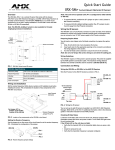
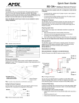
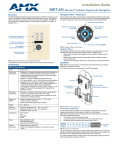
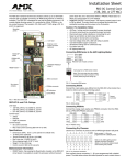
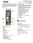
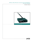
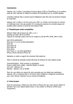
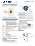
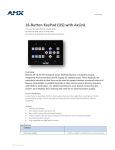
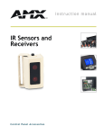
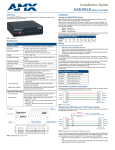
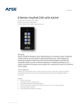
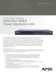
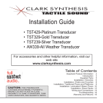
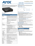
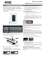
Quick Start Guide
AXD-IR+ WallMount Remote IR Receiver
Overview
The AXD-IR+ (FIG. 1) is a remote IR receiver for use with both AMX
Axcess/NetLinx Central Controllers and operates via the AXlink bus to
remotely control AXlink devices. The AXD-IR+ is in a UniMount wall panel
that fits into most US-style single-gang enclosures. The AXD-IR+ works
with AMX 38 kHz or 455 kHz IR transmitters.
Note: The AXR-IRSM+ swivel-mount version is also available for wall or
ceiling installations:
Note: The unit will not operate with one set of pins configured for
38 kHz and the other set of pins configured for 455 kHz.
•
To receive 455 kHz (default setting), position both jumpers on pins
1 and 2 (away from the edge of the circuit boards).
•
To receive 38 kHz, position both jumpers on pins 2 and 3 (near the
edge of the circuit boards).
Setting the AXlink Device Number
1.
Locate the 8-position Device DIP switch (FIG. 2).
2.
Set the DIP switch according to the DIP switch values shown below.
Switch 1 2 3 4
Value
5
6
7
8
1 2 4 8 16 32 64 128
The device number is set by the total value of DIP switch positions that
are ON (down). The Axcess software program in your system typically
uses device numbers 128 through 255 for the panels.
As an example, the DIP switch in FIG. 4 defines device number 129
(1+128=129).
FIG. 4 Example Device DIP Switch set to 129
Note: If you later change the device number, remove and reconnect
the AXlink connector to enter the new device number into memory.
FIG. 1 AXD-IR+ UniMount IR receiver
AXD-IR+ Specifications
Dimensions (HWD):
4.68" x 2.93" x 1.44" (118.87 mm x 74.42 mm x 36.58 mm)
Sensor IR Validation Level
Available Colors:
White (FG456-10) and Black (FG456-11)
Receive Frequencies:
38 / 455 kHz (user-selectable)
The IR validation level is set on the receiving device (such as an
AXC-RCVI).
Mounting:
Mounts into most US-style single-gang enclosures.
Setting the IR Validation Level
Weight:
7.8 oz. (218.4 g)
Power Consumption:
35 mA
An IR transmitter must send repetitions of data for the receiver to accept it
as valid data. In some installations, a light wall color or other physical
condition may interfere with the sensor's or receiver's ability to sense the
transmitted signal. The signal may reflect or bounce and become distorted.
The receivers can be set to use either two or three repetitions of sequential
signals to validate and accept the signal data.
Wiring and Installation
Set the receive frequency, AXlink device number and IR validation level
before installing the AXD-IR+. FIG. 2 illustrates the location of key
components on the AXD-IR+ circuit board.
Perform the following steps to set the receiver's IR level.
IR Validation
Jumper Pins
1.
8-position
AXlink Device
DIP Switch
Locate the IR jumper pins (J1) (FIG. 5) on the circuit board (FIG. 2).
2
AXlink
Connector
2
3
J1
Setting for 2 validations
3
J1
Setting for 3 validations
FIG. 5 IR validation jumper pin settings
2.
Receive Frequency
Jumper Pins
FIG. 2 Location of key components on the AXD-IR+ circuit board
Setting the Receive Frequency
Use the set of jumper pins on the corner of the circuit board to set the
receive frequency. FIG. 3 illustrates the configuration of the jumpers..
IR SNSR
38/455
kHz
Setting for 38 kHz
IR SNSR
38/455
kHz
Setting for 455 kHz
FIG. 3 Receive frequency jumper settings
Position the IR validation jumper (FIG. 5) to select the number of valid
IR data repetitions to be accepted:
•
Position the jumper at 2 to have the unit validate 2 sequential signals.
•
Position the jumper at 3 to have the unit validate 3 sequential signals.
Wiring the IR Sensors and Receivers
The AXD-IR+ uses a 4-pin AXlink connector for power and data. If the
distance between the receiver and Central Controller exceeds power
consumption limits, you can connect a local 12 VDC power supply to the
AXlink connector.
Preparing Captive Wires
Checking IR Data Status
You will need a wire stripper and a flat-blade screwdriver to prepare the
captive wires:
Locate the red IR Data LED on the front of the unit. Point the system's
AMX transmitter towards the sensor and press a button. The IR Data LED
lights when the unit receives data.
1.
Strip 0.25 inch (6.35 mm) of wire insulation off all wires.
2.
Insert each wire into the appropriate opening on the connector
according to the wiring diagrams in this section.
3.
Turn the flat-head screws clockwise to secure the wire in the
connector.
If the IR Data LED on the unit does not light:
Note: Do not over-torque the screw. Doing so can bend the seating
pin.
•
Verify that the transmit LED on the transmitter lights when you press
a button.
•
Check the wiring to the unit.
•
Verify that the transmitter frequency is properly configured.
Checking AXlink Status
Wiring Guidelines
The AXlink LED lights to indicate AXlink power/data status as follows:
The AXD-IR+ requires 12 VDC power to operate properly. The power is
supplied by the AMX system's AXlink cable. The maximum wiring distance
between the Central Controller and the receiver is determined by power
consumption, supplied voltage, and the wire gauge used for the cable.
The following table lists wire sizes and the maximum lengths allowable
between the receiver and the Central Controller. The maximum wiring
lengths are based on a minimum of 13.5 volts available at the Central
Controller's power supply.
Maximum Wiring Length
Distance
18 AWG
3000 feet (914.40 m)
20 AWG
2121.64 feet (646.68 m)
22 AWG
1,322.75 feet (403.17 m)
24 AWG
833.80 feet (254.14 m)
Indicates power is active and AXlink communication is working.
• 2 blinks per second
Indicates the devices specified in the Master program do not match the
devices found.
• 3 blinks per second
Indicates AXlink communication error.
• Full On
Indicates the following conditions:
• There is no AXlink control or activity, but power is On.
• The Axcess program is not loaded.
If the LED is on and not flashing, disconnect the AXlink connector and
recheck all AXlink connections. Then, reconnect the AXlink connector to
the panel and verify the LED is flashing once per second.
Wiring Specifications @ 35 mA
Wire Size
• 1 blink per second
Mounting the AXD-IR+
1.
If you install the unit farther from the Central Controller than
recommended in this table, connect an external 12 VDC power supply, as
shown in the following wiring diagrams.
2.
Gently remove the bezel from the wallplate.
3.
Place the panel in the wallbox and align the screw holes with the
mounting holes on the panel.
4.
Connection and Wiring
Wiring the AXD-IR+ or the AXR-IRSM+ to AXlink
1
2
3
4
GND
AXM
AXP
PWR
Turn the unit over and locate the AXlink connector.
a.
Connect the unit to AXlink data/power bus.
b.
Check the AXlink LED (should blink once per second).
5.
Fasten the panel to the wallbox using the screws supplied with the
panel.
6.
Snap the wallplate back on the bezel.
Install the AXlink data/power bus wiring as shown in FIG. 6.
GND 1
AXlink connector AXM 2
on the AXD-IR+ AXP 3
PWR 4
For wall or podium mounting (FIG. 8), AMX recommends mounting
the AXD-IR+ in a standard 1-gang wallbox with a minimum internal
clearance of 1 3/4" (W) x 2 5/8" (H) x 1 5/8" (D).
Central
Controller
FIG. 6 AXlink wiring
Using the AXlink Connector with an External 12 VDC Power Supply
Use a 12 VDC power supply when the distance between the Central
Controller and the sensors or receivers exceeds the limits described in the
Wiring Specifications table above. Make sure to connect only the GND
wire on the AXlink connector when using a 12 VDC power supply (FIG. 7).
PWR
GND
12 VDC
Power
Supply
Install unit using supplied #6-32
machine screws at these locations
AXlink connector
on the AXD-IR+
GND
AXM
AXP
PWR
1
2
3
4
1
2
3
4
GND
AXM
AXP
PWR
bezel
wall plate
FIG. 8 AXD-IR+ Mounting Dimensions
Central
Controller
FIG. 7 AXlink wiring with an external 12 VDC power supply
Note: Do not connect the PWR wire to the AXlink connector's PWR
(+) terminal on the Central Controller's side.
AMX Corporation reserves the right to alter specifications without notice at any time.
For full warranty information, refer to the AMX Instruction Manual(s) associated with your Product(s).
042-004-2747 6/05 ©2005
AMX Corporation. All rights reserved. The AMX logo is a trademark of AMX Corporation. AMX reserves the right to alter specifications without notice at any time.
3000 RESEARCH DRIVE, RICHARDSON, TX 75082 • 800.222.0913 • fax 469.624.7153 • technical support 800.932.6993 • www.amx.com
93-0456-10
REV: B