1
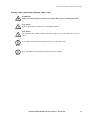
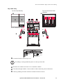
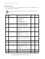
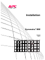
Installation Symmetra MW ® 1000 kW 480 V ~ ~ Contents Safety ......................................................................1 IMPORTANT SAFETY INSTRUCTIONS - SAVE THESE INSTRUCTIONS . . . . . . . . . . . . . . . . . . . . . . . . . . 1 Symbols used in this guide . . . . . . . . . . . . . . . . . . . . . . . . . 1 Installation safety . . . . . . . . . . . . . . . . . . . . . . . . . . . . . . . 2 System Overview......................................................3 UPS Sections . . . . . . . . . . . . . . . . . . . . . . . . . . . . . . . . . . . . . . . 3 Serial number . . . . . . . . . . . . . . . . . . . . . . . . . . . . . . . . . . 3 Inverter Section . . . . . . . . . . . . . . . . . . . . . . . . . . . . . . . . . 3 Control Section . . . . . . . . . . . . . . . . . . . . . . . . . . . . . . . . . 3 Input/Output Section . . . . . . . . . . . . . . . . . . . . . . . . . . . . . 3 Configurations . . . . . . . . . . . . . . . . . . . . . . . . . . . . . . . . . . . . . 4 Configuration 1 (Inverter Section placed to the left) . . . . . . . . 4 Configuration 2 (Inverter Section placed to the right) . . . . . . . 5 External Bypass Static Switch. . . . . . . . . . . . . . . . . . . . . . . . . . . 6 Serial number . . . . . . . . . . . . . . . . . . . . . . . . . . . . . . . . . . 6 Electrical Installation ................................................7 Typical UPS Wiring Principle . . . . . . . . . . . . . . . . . . . . . . . . . . . 7 Power wiring overview . . . . . . . . . . . . . . . . . . . . . . . . . . . . 7 External disconnection switches . . . . . . . . . . . . . . . . . . . . . 8 Input/Output wiring precautions . . . . . . . . . . . . . . . . . . . . . 8 Top Cable Entry. . . . . . . . . . . . . . . . . . . . . . . . . . . . . . . . . . . . . 9 Preparing for top cable entry (default) . . . . . . . . . . . . . . . . . 9 Battery cable connections (top cable entry) . . . . . . . . . . . . . 10 Ground and AC cable connections (top cable entry) . . . . . . . 12 Symmetra MW 1000 kW 480 V Installation - 990-4112E i Bottom Cable Entry . . . . . . . . . . . . . . . . . . . . . . . . . . . . . . . . . 13 Preparing for bottom cable entry . . . . . . . . . . . . . . . . . . . . 13 Battery cable connections (bottom cable entry) . . . . . . . . . . 15 Ground and AC cable connections (bottom cable entry) . . . . 17 Bypass Static Switch Wiring . . . . . . . . . . . . . . . . . . . . . . . . . . . 18 Top cable entry . . . . . . . . . . . . . . . . . . . . . . . . . . . . . . . . 19 Bottom cable entry . . . . . . . . . . . . . . . . . . . . . . . . . . . . . 20 Communication cable overview . . . . . . . . . . . . . . . . . . . . . . . . 21 Relay Board (Optional) . . . . . . . . . . . . . . . . . . . . . . . . . . . . . . 22 Location of optional Relay Board . . . . . . . . . . . . . . . . . . . . 22 Communication cables with optional Relay Board . . . . . . . . 23 Relay Board functions . . . . . . . . . . . . . . . . . . . . . . . . . . . 24 Specifications ........................................................ 27 Low-Impedance/High-Impedance Grounding . . . . . . . . . . . . . . 27 Low-impedance grounding . . . . . . . . . . . . . . . . . . . . . . . . 27 High-impedance grounding . . . . . . . . . . . . . . . . . . . . . . . 27 Electrical Specification . . . . . . . . . . . . . . . . . . . . . . . . . . . . . . . 29 Installation Planning Data . . . . . . . . . . . . . . . . . . . . . . . . 29 AC Input . . . . . . . . . . . . . . . . . . . . . . . . . . . . . . . . . . . . 30 DC Input . . . . . . . . . . . . . . . . . . . . . . . . . . . . . . . . . . . . 30 AC Output . . . . . . . . . . . . . . . . . . . . . . . . . . . . . . . . . . . 31 AC Input External Bypass SSW . . . . . . . . . . . . . . . . . . . . . 31 Heat Dissipation . . . . . . . . . . . . . . . . . . . . . . . . . . . . . . . 31 Notes . . . . . . . . . . . . . . . . . . . . . . . . . . . . . . . . . . . . . . 31 Table 2 - Table 310-16 (National Electrical Code) . . . . . . . . . 32 Recommended cable, bolt, and lug sizes . . . . . . . . . . . . . . . 34 Torque specifications . . . . . . . . . . . . . . . . . . . . . . . . . . . . 34 Required Breaker Settings . . . . . . . . . . . . . . . . . . . . . . . . . . . . 35 Input and upstream breakers — minimum settings . . . . . . . . 35 Output and downstream breakers — minimum settings . . . . 35 General Specifications 480 V . . . . . . . . . . . . . . . . . . . . . . . . . . 37 ii Symmetra MW 1000 kW 480 V Installation - 990-4112E Safety IMPORTANT SAFETY INSTRUCTIONS - SAVE THESE INSTRUCTIONS This guide contains important instructions for SYMF1000KG that should be followed when handling the UPS, External Bypass Static Switch, Battery Enclosures, and Batteries. Symbols used in this guide WARNING! Indicates an electrical hazard, which, if not avoided, could result in injury or death. CAUTION! Indicates a hazard, which, if not avoided, could result in injury or death. Indicates important information. Note Indicates that more information is available on this subject in a different section of this manual. Indicates that more information is available on the same subject in a different manual. See also Main Protective Earthing Terminal symbol. Ground symbol. Symmetra MW 1000 kW 480 V Installation - 990-4112E 1 Safety: IMPORTANT SAFETY INSTRUCTIONS - SAVE THESE INSTRUCTIONS Installation safety EPO Press the EPO (Emergency Power Off) button to switch off all AC and DC power supply to connected equipment in the room. The EPO is typically located on a wall in the room in which the UPS is installed. See “Communication cable overview” section for information on how to wire the UPS to the EPO. WARNING! Before starting installation, check and test that all AC and DC power source breakers are in open position. WARNING! Only personnel trained in the construction and operation of the equipment, and the electrical and mechanical hazards involved, may install or remove system components. CAUTION! Do not use High Voltage Testing Equipment. This equipement will destroy the electronic circuits in the unit. CAUTION! The system is equipped with an optional auto-start function, enabling the system to start without any warning when power is applied. CAUTION! All wiring must be in accordance with applicable national and/or local electrical codes. This unit contains components that are sensitive to electrostatic discharge (ESD). Follow proper ESD procedures to avoid severe damage to electronic components. Note 2 This equipment has been tested and found to comply with the limits for a Class A digital device, pursuant to Part 15 of the FCC Rules. These limits are designed to provide reasonable protection against harmful interference when the equipment is operated in a commercial environment. This equipment generates, uses, and can radiate radio frequency energy and, if not installed and used in accordance with the Installation Manual, may cause harmful interference to radio communications. Operation of this equipment in a residential area is likely to cause harmful interference, in which case the user will be required to correct the interference at his own expense. Symmetra MW 1000 kW 480 V Installation - 990-4112E System Overview UPS Sections The UPS system consists of an 1000 kW Inverter Section, a Control Section, an Input/Output Section and an External Bypass Static Switch Section. Serial number The serial number is stated on the type label behind the finishing panel above the display unit. Remove finishing panel to see serial number. Inverter Section The Inverter Section regulates the UPS output and operates from battery power in the event of utility input loss. Control Section The Control Section controls and monitors the UPS and the Main Static Switch (incorporated in the Control Section). Input/Output Section The Input/Output Section provides electrical connection of input and output. Symmetra MW 1000 kW 480 V Installation - 990-4112E 3 Configurations The UPS system can be configured in two ways. The Inverter Section can be placed either to the left or to the right of the Control Section. The two configurations are shown below. Configuration 1 (Inverter Section placed to the left) ~ 2032 mm/80 in ~ 1067 mm/42 in Inverter Section Control Section Input/Output Section Width: 2112 mm/83.15 in Width: 1012 mm/39.84 in Width: 1014 mm/39.92 in Total width of UPS sections: 4138 mm/163 in Weight: Without Power Modules: 4197 kg/9233 lb With Power Modules: 5049 kg/11108 lb 4 Symmetra MW 1000 kW 480 V Installation - 990-4112E System Overview: Configurations 2032 mm/80 in Configuration 2 (Inverter Section placed to the right) 1067 mm/42 in Input/Output Section Control Section Inverter Section Width: 1014 mm/39.92 in Width: 2112 mm/83.15 in Width: 1012 mm/39.84 in Total width of UPS sections: 4138 mm/163 in Weight: Without Power Modules: 4197 kg/9233 lb With Power Modules: 5049 kg/11108 lb Symmetra MW 1000 kW 480 V Installation - 990-4112E 5 External Bypass Static Switch The External Bypass Static Switch (External Bypass SSW) transfers the load (manually or automatically) from the UPS to an alternate source without interrupting the power to the load. ~ 2032 mm/80 in ~ 1067 mm/42 in External Bypass Static Switch Width: 1014 mm/39.82 in Weight: 460 kg/1012 lb Serial number The serial number is stated on the type label behind the finishing panel above the display unit. Remove finishing panel to see serial number. 6 Symmetra MW 1000 kW 480 V Installation - 990-4112E Electrical Installation Typical UPS Wiring Principle Power wiring overview See separate guide on parallel operation for wiring overview in parallel systems. See also AC Mains Input Lugs Q1 480 V, 3PH, 3W & GND Q5 2 2 Battery 1 Battery 2 Battery Breakers 7 SSW 5 Q7 External Battery UPS 7 Q8 2 2 2 2 Q2 Q6 2 KK 4 Q3 KK 4 Q4 480 V, 3PH, 3W & GND 4 LBB KK 4 Output Load Lugs 1. SOURCE AND AC CABLING MUST BE 480 VOLT, WYE CONNECTED, 3 PHASE, 3 WIRE + GROUND (CONTACT APC IF OTHER). 2. DASHED LINES BETWEEN UNITS ( — — — ) REPRESENT AC/DC CABLING PROVIDED BY OTHERS. 3. ALL AC CIRCUIT BREAKERS ARE 100% CONTINUOUS DUTY RATED WITH 24 VOLT DC SHUNT TRIPS AND 2A/2B AUXILIARY CONTACTS. 4. OPTIONAL COMPONENTS 5. SEPARATE CONDUITS. TWO WIRE + GROUND 6. UPS INPUT AND OUTPUT CONDUCTORS MUST BE IN SEPARATE AMPERE RATINGS. 7. UPS AND STATIC BYPASS WITHSTAND 200,000 SYMMETRICAL AMPERES. 8. INSTALLATION MUST COMPLY WITH ALL APPLICABLE NATIONAL AND LOCAL CODES. Symmetra MW 1000 kW 480 V Installation - 990-4112E 7 Electrical Installation: Typical UPS Wiring Principle External disconnection switches WARNING! The UPS has no internal manual disconnect devices to switch off external AC (Q1 and Q5) and DC (Q7 and Q8) input power. Ensure that disconnection devices are available as separate components for this installation. Note The installer must provide each external disconnection device for this UPS system with labels displaying the following text: “Isolate the Uninterruptible Power Supply (UPS) as instructed in the User Guide before working on circuit.” Input/Output wiring precautions WARNING! Only personnel trained in the construction and operation of the equipment, and the electrical and mechanical hazards involved, may install or remove system components. WARNING! Supply the UPS from a dedicated, grounded, 3-wire Wye service. CAUTION! All wiring must be in accordance with applicable national and/or local electrical codes. Use only UL-approved cable lugs. Note Note 8 Use only UL-approved cables. Use only stranded copper conductors. Refer to National Electric Code for wiring and protection. Refer to bolt and lug table in the “Specifications” section. Symmetra MW 1000 kW 480 V Installation - 990-4112E Top Cable Entry Preparing for top cable entry (default) Cable entry in top cover of Input/Output Section. Top view Battery cable entry AC IN cable entry M6 Bolt 1.75 in / 44.45 mm Battery cable entry 1.75 in / 44.45 mm 2.3 in / 58 mm AC OUT cable entry IN/OUT power cable (top entry) BAT 1 BAT 2 Top view AC IN AC OUT 90 L3 IN 95 L3 OUT 91 L2 IN 94 L2 OUT 92 L1 IN 93 L1 OUT L1 IN L1 OUT 92 93 91 94 90 95 L2 IN L2 OUT L3 IN L3 OUT Loosen the 8 bolts in cable entry covers. Drill holes for conduits in areas shown. Re-fit the covers and install the conduits. Install cable lugs on busbars. Use M12 bolts. Symmetra MW 1000 kW 480 V Installation - 990-4112E 9 Electrical Installation: Top Cable Entry Battery cable connections (top cable entry) WARNING! Make sure that the battery breakers are open (OFF) prior to running the cables. CAUTION! Refer to the battery manufacturer’s installation manual. CAUTION! The minimum DC voltage rating of the battery supply over-current protective device is 500 V. Over-current protection for the battery circuit is required by code. Note BAT 1 and BAT 2 cables MUST be run in separate conduits. Note 10 Symmetra MW 1000 kW 480 V Installation - 990-4112E Electrical Installation: Top Cable Entry Top view of Input/Output Section Battery cable entry AC IN cable entry 1.75 in / 44.45 mm Battery cable entry 1.75 in / 44.45 mm 2.3 in / 58 mm AC OUT cable entry IN/OUT power cable (top entry) Battery 1 Battery 2 (BAT 1 +/-) (BAT 2 +/-) BAT 1BAT 1- BAT 2+ L1 In L1 Out L2 In L2 Out L3 In L3 Out BAT 2+ BAT 1+ BAT 2BAT 1+ BAT 2- Front view of Input/Output Section Feed the battery cables through the top of Input/Output Section. Connect cables from battery system as illustrated. Connect cables from battery system as illustrated. Symmetra MW 1000 kW 480 V Installation - 990-4112E 11 Electrical Installation: Top Cable Entry Ground and AC cable connections (top cable entry) Equipment grounding cables for Battery 2 and AC Out Output circuit grounding bar Grounding electrode conductors (red) for Battery 1 & AC IN Midpoint bonding jumper 1.75 in / 44.45 mm 1.75 in / 44.45 mm 2.3 in / 58 mm Feed the AC and ground cables through the top of Input/Output Section as illustrated. Connect the cables as illustrated. 12 Symmetra MW 1000 kW 480 V Installation - 990-4112E Bottom Cable Entry Preparing for bottom cable entry Cable entry in bottom cover of Input/Output Section Top view Battery cable entry AC IN cable entry M6 Bolt 1.75 in / 44.45 mm Battery cable entry 1.75 in / 44.45 mm 2.3 in / 58 mm AC OUT cable entry Top view Front view BAT 1 BAT 2 M14 M14 M14 M10 M10 AC OUT AC IN 90 L3 IN M10 L2 IN M10 92 L1 IN 95 L3 OUT M10 L2 OUT 93 L1 OUT M14 M10 M10 L1 IN L2 IN L3 IN BAT 1 90 95 L1 OUT 91 94 L2 OUT 92 93 L3 OUT BAT 2 Top view AC IN 90 L3 IN AC OUT 95 L3 OUT L2 IN L2 OUT 92 L1 IN 93 L1 OUT IN/OUT power cable (bottom entry). Symmetra MW 1000 kW 480 V Installation - 990-4112E 13 Electrical Installation: Bottom Cable Entry Preparation for bottom cable entry a. Loosen bolts of both cable entry covers and remove. b. Drill holes for conduits for AC, Battery, and Output circuit grounding electrode cable in areas shown. c. Install conduits. d. Remount covers. Interchange of AC IN busbars for bottom entry a. Remove nuts from M14 bolts at busbars 90 and 92. b. Remove bolt, washer and fuse. c. Remove bolts from M10 at busbars 90 and 92. d. Remove busbars 90 and 92 at AC IN. e. Move the two front insulators in the topmost busbar position two stud positions to the front. f. Move the two front insulators in the lowest busbar position two stud positions to the rear. g. Install busbar 90 in original position of busbar 92. h. Install busbar 92 in original position of busbar 90. i. Reattach bolts at busbars 90 and 92. j. Install cable lugs on busbars using M12 bolts. Interchange of AC OUT busbars for bottom entry a. Remove nuts from M14 bolts at busbars 93 and 95. b. Remove bolt, washer and fuse. c. Remove bolts from M10 at busbars 93 and 95. d. Remove busbars 93 and 95 at AC OUT. e. Move the two front insulators in the topmost busbar position two stud positions to the front. f. Move the two front insulators in the lowest busbar position two stud positions to the rear. g. Install busbar 93 in original position of busbar 95. h. Install busbar 95 in original position of busbar 93. i. Reattach bolts at busbars 93 and 95. j. Install cable lugs on busbars using M12 bolts. Moving busbar for grounding a. Move busbar for grounding from upper right corner to lower left corner as illustrated. 14 Symmetra MW 1000 kW 480 V Installation - 990-4112E Electrical Installation: Bottom Cable Entry Battery cable connections (bottom cable entry) WARNING! Make sure that the battery breakers are open (OFF) prior to running the cables. CAUTION! Refer to the battery manufacturer’s installation manual. CAUTION! The minimum DC voltage rating of the battery supply over-current protective device is 500 V. Over-current protection for the battery circuit is required by code. Note BAT 1 and BAT 2 cables MUST be run in separate conduits. Note Symmetra MW 1000 kW 480 V Installation - 990-4112E 15 Electrical Installation: Bottom Cable Entry Top view of Input/Output Section 1.75 in / 44.45 mm Battery cable entry AC IN cable entry 1.75 in / 44.45 mm Battery cable entry 2.3 in / 58 mm AC OUT cable entry Front view of Input/Output Section BAT 1- BAT 2+ L1 In L1 Out L2 In L2 Out L3 In BAT 1- BAT 2+ L3 Out BAT 2- BAT 1+ BAT 1+ BAT 2- Battery 1 BAT 1 +/-) Battery 2 (BAT 2 +/-) IN/OUT power cable (bottom entry) Feed the battery cables through the bottom of Input/Output Section. Connect cables from battery system as illustrated. Connect cables from battery system as illustrated. 16 Symmetra MW 1000 kW 480 V Installation - 990-4112E Electrical Installation: Bottom Cable Entry Ground and AC cable connections (bottom cable entry) Output circuit grounding bar Midpoint bonding jumper Equipment grounding cables for Battery 2 & AC OUT Equipment grounding cables for Battery 1 & AC IN Equipment grounding bar Battery 2 Battery 1 1.75 in / 44.45 mm 1.75 in / 44.45 mm 2.3 in / 58 mm Feed the AC and ground cables through the bottom of Input/Output Section as illustrated. Connect cables as illustrated. Symmetra MW 1000 kW 480 V Installation - 990-4112E 17 Bypass Static Switch Wiring WARNING! Use only manual reset protection as input over-current protection. WARNING! Over-current protection required by code. WARNING! The UPS has no internal manual disconnect devices to switch off external AC (Q1 and Q5) and DC (Q7 and Q8) input power. Ensure that disconnection devices are available as separate components for this installation. CAUTION! The External Bypass Static Switch is not provided with built-in backfeed protection. The breaker is controlled from the External Bypass SSW and will be tripped in case of backfeed. Note The installer must provide each external disconnection device for this UPS system with labels displaying the following text: “Isolate the Uninterruptible Power Supply (UPS) as instructed in the User Guide before working on circuit.” The installation of the External Bypass Static Switch must comply with local and national codes. Note Run matched set of phase cables in the same cable run(s). Do not separate phases into different cable runs. Note For information on cable lugs, cable ratings, over-current protection and the disconnection switches, refer to “Specifications” . Electrical Installation: Bypass Static Switch Wiring Top cable entry Top view of top cable entry Top view of AC IN & OUT cable connections L3 OUT L3 IN L2 OUT L2 IN PE L1 OUT L1 IN X017 X012 X008A X014B X013 X014A X008B X011 X405 X010 Normal Normal X007 X021 UPS Summary X022 Port for communication cables ~ L1 IN L1 OUT 1.75 in / 44.45 mm L2 IN L2 OUT ~ L3 IN L3 OUT 1.75 in / 44.45 mm 2.3 in / 58 mm Loosen the 8 bolts to remove top cover. No drilling or cutting should take place over the top of the UPS. Note Drill holes for conduits. Re-fit the covers. Install the conduits. Feed cables through conduits. Connect cables at cable connection points as illustrated. Connect grounding electrode conductor to busbar locations as shown. Symmetra MW 1000 kW 480 V Installation - 990-4112E 19 Electrical Installation: Bypass Static Switch Wiring Bottom cable entry Top view of AC IN & OUT bottom cable connections Top view of bottom cable entry X017 X012 X008A X014B X013 X014A X008B X011 X405 X010 X007 X021 Normal Normal UPS Summary L1 IN L2 IN L3 IN L1 OUT L2 OUT L3 OUT Communication cable Port PE 1.75 in / 44.45 mm 1.75 in / 44.45 mm 2.3 in / 58 mm Loosen the 8 bolts to remove bottom cover. No drilling or cutting should take place inside the UPS. Note Drill holes for conduits. Re-fit the covers. Install the conduits. Feed cables through conduits. Connect cables at cable connection points as illustrated. Connect grounding electrode conductor to busbar locations as shown. 20 Symmetra MW 1000 kW 480 V Installation - 990-4112E L3 OUT L3 IN L2 OUT L2 IN ~ L1 OUT ~ L1 IN X022 Communication cable overview Terminator 0N-0765 External Bypass Static Switch Maintenance Bypass Panel Relay output X134A 1 1 4 6 5 1 3 Note 3 4 2 3 2 1 1 Q 1 X127A 2 C1 Q 2 X126A + - + 7 X127B 0P4533 8 Q 3 X129 C2 MBP CAN I/O board 2 Q 4 X126B Note 1 - 1 EMO (Display) Q 5 X128 X174 Earth fault sensor X129 12 11 10 9 Q 6 X131 12 3 4 X170 X175 Norm.op X128 2 1 2 X130 X134B X177 2 2 X178 1 2 1 1 2 X177 MBP Breakers X173 Connection plane 0P0957 X134A 2 3 2 1 + 4 5 6 - + - + H3 Lamps X172 8 9 10 7 H4 - + H5 11 1 12 - X176 3 4 2 + - + 5 - Q5 H6 6 + - Q6 24VDC Shunt trip for back feed protection + External Lamp supply VDC or V DC - Max. 250VAC 5A Terminator 0N-0765 UPS Note 1 2 6 7 8 X172 Lamps 9 11 10 12 C2 12 3 4 X170 + C1 1 6 X176 3 4 Q2 5 X173 MBP Breakers 2 1 Q1 + 24VDC Shunt trip Relay output Maintenance Bypass Panel H8 H7 Note 2 Q8 3 1 4 2 3 X183 UVR UVR + Q8 Q7 Temp sensor NTC + Temp sensor NTC + Fuse4 Fuse1 X186 1 2 3 4 5 6 7 8 Fuse3 X133A + - 4 Battery CAN I/O board ID 0 X185 0P4512 X133B 4 X182 + X184 2 3 2 Fuse2 1 2 12 34 X180 1 - 1 Q7 + X181 1 2 3 4 EMO (Display) + 1 2 Backfeed protection Earth fault sensor X174 1 X127A Norm.op X175 2 1 EPO out X185 1 2 2 Note 3 X129 1 1 2 2 1 X128 9 10 11 12 X129 2 + 8 X128 + MBP CAN I/O board1 0P4533 7 X130 6 X127B 1 External EPO 2 placed on wall 4 5 X126B 5 X177 2 3 X126A 4 1 X131 X133A 3 3 1 2 2 2 1 1 X178 Connection plane 0P0957 EPO out X177 X134A 4 X134B X134A Note 1: Contact APC Application Team for correct sizing. Note 2: H7, H8 = 5V LED Note 3: Q2, Q4 and Q6 are optional. If Q2 is not present pins 3 and 4 must be shorted on both boards. If Q4 is not present pins 7 and 8 must be shorted on both boards. If Q6 is not present pins 11 and 12 must be shorted on both boards. Symmetra MW 1000 kW 480 V Installation - 990-4112E 21 Relay Board (Optional) NC 3 1 2 3 1 2 3 1 2 3 1 2 3 1 2 3 1 2 3 1 2 3 1 2 3 Location of optional Relay Board 22 Symmetra MW 1000 kW 480 V Installation - 990-4112E Electrical Installation: Relay Board (Optional) Communication cables with optional Relay Board External Lamp supply VAC or V DC Max. 250VAC 5A 24VDC Shunt trip Symmetra MW 1000 kW 480 V Installation - 990-4112E 23 Electrical Installation: Relay Board (Optional) Relay Board functions The Relay Board informs the user of the operation mode, status, and alarm conditionsand has 8 ports on the input side and 16 output terminals. Use Normally Closed (NC) contacts for Fail safe Mode and Normally Open (NO) for Active on. Note 24 Relay ID Name Events that will trigger the alarm Mode Comment K1 Common Alarm • Any of the functions below, except relays K8, K9, K10, K11; • Inverter section fault; • Main PSU fault; • System locked in operation mode; • Internal memory fault; • Internal communication fault. Fail safe Warning K2 Battery voltage out of tolerance • DC voltage is too high (shut down); • DC voltage is under warning level; • DC voltage is low (shut down). Fail safe Warning K3 Mains out of tolerance • Mains voltage RMS value is out of tolerance; • Mains waveform not accepted (fast detector); • Mains frequency is out of tolerance. Fail safe Warning K4 Bypass out of tolerance • Bypass voltage RMS value is out of tolerance; • Bypass waveform not accepted (fast detector); • Bypass frequency is out of tolerance. Fail safe Warning K5 Battery condition fault • Battery monitor has detected a weak battery; • Battery monitor has detected a defective battery. Fail safe Fault K6 Battery disconnected • Battery breaker tripped/open. Fail safe Fault K7 System overload • Output load exceeded 100%; • Delta Inverter current limiter is active; • Main Inverter current limiter is active. Fail safe Fault K8 Output out of tolerance • Output voltage RMS value is out of tolerance; • Output waveform not accepted (fast detector); • Output frequency is out of tolerance. Fail safe Fault K9 Normal operation • UPS is running in normal operation. Active on Opr. mode K10 Battery operation • UPS is running in battery operation. Active on Opr. mode Symmetra MW 1000 kW 480 V Installation - 990-4112E Electrical Installation: Relay Board (Optional) Relay ID Name Events that will trigger the alarm Mode Comment K11 Bypass operation • UPS is running in normal operation/ bypass operation according to AS400/ Novell. Active on Opr. mode K12 Maintenance bypass ON • The maintenance bypass switch is active. Active on Opr. mode K13 Stand-by operation • UPS is in stand-by operation. Active on Opr. mode K14 Boost charge operation • UPS is boost charging the batteries. Active on Opr. mode K15 Fan fault • Blocked or faulty fan. Fail safe Fault K16 High equipment temperature or inverter fuse blown • Static Switch temperature is high; • Main Inverter failure (high temperature or blown fuse); • Delta Inverter temperature is high; • Magnetics temperature is high; • Isolation Transformer temperature is high (optional); • Battery temperature is high. Fail safe Warning IN1 Generator active • System on generator System is running on generator. Battery charging is derated. IN2 Battery room ventilation fault • Battery room ventilation Ventilation fault in battery room. Battery charging is off. IN3 IN8 Reserved for future use Symmetra MW 1000 kW 480 V Installation - 990-4112E 25 Specifications Low-Impedance/High-Impedance Grounding The Symmetra® MW is easily integrated into either a low-impedance (solidly) grounded Wye system, or a high-impedance grounded system. In a low-impedance grounded system (most common), the power source (utility, generator, or UPS) is solidly grounded. In the event of a down-stream ground fault, the fault current will have a path back to the source, and the over-current device feeding the faulted part of the installation will trip and isolate the fault. In a high-impedance grounded system, the source is grounded with an impedance (grounding resistor). In the event of a down-stream fault, the fault current will be limited by the impedance of the grounding resistor. The value of a high-impedance system is its ability to maintain operation with a given system fault to ground, i.e. the over-current device will only trip at line-to-line faults or double ground faults. For a high-impedance system to provide enhanced power system reliability and availability, a ground-fault monitoring/alarm system is required. Low-impedance grounding For low-impedance grounding, verify the presence of the copper midpoint bonding jumper. For location of the jumper, see “Ground and AC cable connection” in Installation Guide. Connect the output circuit grounding electrode conductor to a grounding electrode in accordance with NEC 1999, article 250-26. Grounding electrode conductor to be supplied by the customer. Note High-impedance grounding For high-impedance grounding, remove the pre-installed copper midpoint bonding jumper. For location of the jumper, see “Ground and AC cable connection” in Installation Guide. Install ground-fault detection circuit in accordance with NEC 1999, article 250-36. Symmetra MW 1000 kW 480 V Installation - 990-4112E 27 Specifications: Low-Impedance/High-Impedance Grounding For high-impedance grounding, the installation must include ground-fault detection circuitry. Note From an external grounding resistor, and through a separate conduit, connect a cable to the output circuit grounding bar. 28 Symmetra MW 1000 kW 480 V Installation - 990-4112E Electrical Specification Installation Planning Data Maintenance Bypass Panel Q3 Q5 External Bypass SSW Q6 Optional Q4 Service (480V 3-phase, 3- wire grounded Wye) Optional UPS Q2 Q1 Output (480V 3-phase, 3-wire only) Optional Battery Q7 Breaker 1 Q8 Battery Breaker 2 The installation is a typical installation including ancillary equipment, which is available from APC. Note UPS and External Bypass Static Switch feed must be generated from synchronized sources. Note WARNING! Supply the UPS from a dedicated, grounded 3-wire Wye service. WARNING! The UPS has no internal manual disconnect devices to switch off external AC (Q1 and Q5) and DC (Q7 and Q8) input power. Ensure that disconnection devices are available as separate components for this installation. CAUTION! Ensure clockwise phase rotation (L1, L2, L3) of input voltages. Symmetra MW 1000 kW 480 V Installation - 990-4112E 29 Specifications: Electrical Specification CAUTION! AC and DC disconnect switches and over-current protection must be included in the installation. All wiring must comply with all applicable national and/or local electrical codes. Note Max. prospective RMS short-circuit current on input terminals: 200 kA Max. prospective RMS short-circuit current on battery terminals: 50 kA Note AC Input AC Input AC Input Input Rating 1000 kW/kVA Power Factor 1 Input Voltage 480 V Input Frequency 60 Hz Nominal Input Current (note 1) 1240 A Maximum Input Current (note 2) 1364 A Input Current Limitation (note 3) 1564 A Recommended Cable per phase (notes 4, 6, 7, a, b, c) 5 × 500 kcmil DC Input DC Input Nominal Voltage (note 5) 2 x 384 V INom Discharge (note 8) 1356 A IMax Discharge (note 9) 1595 A Recommended cable (per pole) 5 × 500 kcmil CAUTION! The minimum DC voltage rating of the battery supply over-current protective device is 500 V. 30 Symmetra MW 1000 kW 480 V Installation - 990-4112E Specifications: Electrical Specification AC Output AC Output Voltage 480 V Current Nom 1203 A Max (note 11) 1504 A Recommended cable (per phase) 5 × 500 kcmil AC Input External Bypass SSW The External Bypass SSW is designed to accommodate a continuous overload of 25%. AC Input External Bypass SSW External Bypass SSW Max Input Current (100% load) 1203 A Heat Dissipation 105.5 kBTU/hr (note 10) Notes 1. Nominal (Nom): Input current based on rated load. 2. Maximum (Max): Input current based on full battery recharge + nominal input voltage + rated load. 3. Current limitation (A) through electronic current limiting is based on full battery recharge + nominal load and -15% input voltage (see “Required Breaker Settings” ). 4. Input, Output and Battery1 and Battery2 circuit cables shall be run in separate conduits or raceways. Cables shall be rated at 600 V as a minimum. 5. Nominal battery voltage at 2.0 volts/cell. 6. Recommendation: All cables shall be sized in accordance with 2002 NEC 210-19 FPN No. 4 branch feeder voltage drop of 3%. Voltage drop not considered in above chart. Applicationspecific Input Cable Ampacity may vary from above chart. 7. Equipment Grounding Conductors shall be sized in accordance with Table 250-122 of the 2002 NEC and shall be installed in accordance with Article 250 Section VI and Section VII of the 2002 NEC. Grounding Electrode Conductors shall be sized in accordance with Article 250.66 and Table 250.66 of the 2002 NEC and should be installed in accordance with Article 250 Symmetra MW 1000 kW 480 V Installation - 990-4112E 31 Specifications: Electrical Specification Section III of the 2002 NEC. 8. Nominal Battery Discharge current based on rated load, and nominal battery voltage. 9. Maximum Battery Discharge current based on rated load at end of discharge. 10. Heat dissipation calculated at rated load capacity. 11. This current is at 125% of rated load and is electronically current-limited to a maximum of 10 minutes. This value is only provided so the engineer can ensure that the selected AC output circuit over-current device’s time-current characteristic will support this condition. a. Temperature rating of conductors: 194oF (90oC). Reference: Table 310-16 of NEC, 75oC column. Use only copper conductors. 167oF (75oC) cable terminal connectors assumed. b. Reference: NEC Handbook 2002. Consult local codes for possible variations. c. All cable ratings are supplied as guidelines only. These guidelines are recommendations only, and should not be considered substitutes for review and compliance with NEC, national, or local codes. Consult with your licensed engineer for site-specific applications. 86oF (30oC) assumed. Over-current protection provided by others. Table 2 - Table 310-16 (National Electrical Code) National Electrical Code and NEC are registered trademarks of the National Fire Protection Association, Quincy, MA. Allowable Ampacities of Insulated Conductors rated 0 Through 2000 Volts, 60oC Through to 90oC (140oF Through 194oF), Not More Than Three Current-Carrying Conductors in Raceway, Cable, or Earth (Directly Buried), Based on Ambient Temperature of 30oC (86oF). 32 Symmetra MW 1000 kW 480 V Installation - 990-4112E Specifications: Electrical Specification Size AWG or kcmil Temperature Rating of Cables (See Table 310-13) 60oC (140oF) 75oC (167oF) 90oC (194oF) Types TW,UF Types FEPW,RH,RH W,THHW, THW,THWN, XHHW, USE,ZW Types TBS,SA,SIS,FEP, FEPB,MI,RHH, RHW-2,THHN, THHW,THW-2, THWN-2,USE-2, XHH,XHHW,XH HW-2,ZW-2 Copper Size 60oC (140oF) 75oC (167oF) 90oC (194oF) Types TW,UF Types RH,RHW,TH HW,THW, THWN, XHHW,USE Types TBS,SA,SIS,TH HN,THHW,TH W-2,THWN-2, RHH,RHW-2, USE-2,XHH, XHHW, XHHW-2,ZW-2 AWG or kcmil Aluminium or Copper-Clad Aluminium 18 16 14* 12* 10* 8 20 25 30 40 20 25 35 50 14 18 25 30 40 55 20 25 30 20 30 40 25 35 45 12* 10* 8 6 4 3 2 1 55 70 85 95 110 65 85 100 115 130 75 95 110 130 150 40 55 65 75 85 50 65 75 90 100 60 75 85 100 115 6 4 3 2 1 1/0 2/0 3/0 4/0 125 145 165 195 150 175 200 230 170 195 225 260 100 115 130 150 120 135 155 180 135 150 175 205 1/0 2/0 3/0 4/0 250 300 350 400 500 215 240 260 280 320 255 285 310 335 380 290 320 350 380 430 170 190 210 225 260 205 230 250 270 310 230 255 280 305 350 250 300 350 400 500 600 700 750 800 900 355 285 400 410 435 420 460 475 490 520 475 520 535 555 585 285 310 320 330 355 340 375 385 395 425 385 420 435 450 480 600 700 750 800 900 1000 1250 1500 1750 2000 455 495 520 545 560 545 590 625 650 665 615 665 705 735 750 375 405 435 455 470 445 485 520 545 560 500 545 585 615 630 1000 1250 1500 1750 2000 CORRECTION FACTORS Ambient Temp. (oC) 21-25 26-30 31-35 36-40 41-45 46-50 51-55 56-60 61-70 71-80 For ambient temperatures other than 30oC (86oF), multiply the allowable Ampacities shown above by the appropriate factor shown below 1.08 1.00 0.91 0.82 0.71 0.58 0.41 - 1.05 1.00 0.94 0.88 0.82 0.75 0.67 0.58 0.33 - 1.04 1.00 0.96 0.91 0.87 0.82 0.76 0.71 0.58 0.41 1.08 1.00 0.91 0.82 0.71 0.58 0.41 - 1.05 1.00 0.94 0.88 0.82 0.75 0.67 0.58 0.33 - 1.04 1.00 0.96 0.91 0.87 0.82 0.76 0.71 0.58 0.41 Ambient Temp. (oF) 70-77 78-86 87-95 96-104 105-113 114-122 123-131 132-140 141-158 159-176 Reprinted with permission from NFPA 70-2005, National Electrical Code®, Copyright © 2004, National Fire Protection Association, Quincy, MA 02169. This reprinted material is not the complete and official position of the NFPA on the referenced subject, which is represented only by the standard in its entirety. Symmetra MW 1000 kW 480 V Installation - 990-4112E 33 Specifications: Electrical Specification Recommended cable, bolt, and lug sizes Cable Size Bolt hole size Hole spacing Lug width Lug P/N (1)(2) Crimping Tool and Dies 400 kcmil 0.5 in/12.7 mm 1.75 in/44.45 mm 1.39 in/35.31 mm Panduit LCD400-12-6 (or equivalent) Manufacturer recommended crimping tool and dies. 500 kcmil 0.5 in/12.7 mm 1.75 in/44.45 mm 1.54 in/39.12 mm Panduit LCD500-12-6 (or equivalent) Manufacturer recommended crimping tool and dies. 600 kcmil 0.5 in/12.7 mm 1.75 in/44.45 mm 1.70 in/43.18 mm Panduit LCD600-12-6 (or equivalent) Manufacturer recommended crimping tool and dies. Cable lugs are not supplied. Note Torque specifications Torque specifications 34 Bolt Size M8 10 lbf-ft/13.5 Nm Bolt Size M10 22 lbf-ft/30 Nm Bolt Size M12 37 lbf-ft/50 Nm Bolt Size M14 55 lbf-ft/75 Nm Symmetra MW 1000 kW 480 V Installation - 990-4112E Required Breaker Settings The Symmetra® MW is a fault-tolerant system capable of handling and surviving overloads and internal/external faults. The overload performances and fault clearings are possible when the system meets specified minimum requirements for breaker settings. The settings are specified in the tables below, but some of them can also be found in the Electrical Specification section. The settings are all minimum settings and may not result in a drop-out. See separate guide on parallel operation for information on required breaker settings in parallel systems. See also Input and upstream breakers — minimum settings Q1, Q5, and any upstream breaker Duration [S] Current [A] Total load [%] Event/Operation < 0.005 18 kA -- Internal fault clearing ∞ 1880* 130 Overload on-line ∞ 1245 100 On-line ∞ 1370 110 On-line + Max. Battery Charge * Only applicable to Q1 Output and downstream breakers — minimum settings Q2, Q4, Q6, and any downstream breaker Duration [S] Current [A] Total load [%] Event/Operation < 0.005 18 kA -- Internal fault clearing. 60 2406* 200 Overload on-line 600 1504* 125 Overload on-line ∞ 1203 100 On-line * Only applicable to Q2 and Q4 Symmetra MW 1000 kW 480 V Installation - 990-4112E 35 Specifications: Required Breaker Settings 18 kA is the maximum peak let-through current (including safety factor) available during clearing of an internal fault in a 200 kW section or a Power Module. During or after a controlled fault clearing, none of the breakers are allowed to trip on the instantaneous trip setting below the specified value. This is also applicable to the upstream breakers, and a control of the instantaneous trip setting in this part of the installation is required. The maximum peak let-through current is applicable to utility with prospective short-circuit currents up to 200 kA. Note The instantaneous trip setting must not be derated even though the UPS system is derated in system output power. The system size has no influence on the instantaneous trip setting. For derated systems, the APC Application Team provides the correct breaker settings and breaker frame sizes. Note For upstream breakers not mentioned in the table, the APC Application Team provides the correct breaker settings for on-line, overload, and trip currents. Note The following diagram shows a dual utility system in which the upstream breakers are named Q. Correct settings of upstream breaker settings are mandatory. The system can also be configured as a single utility system. Dual Utility Installation Q3 T1 Q Q5 Q6 Q Q1 Q2 T2 36 Symmetra MW 1000 kW 480 V Installation - 990-4112E Q4 General Specifications 480 V Backfeed protection Built-in in the UPS Humidity Max. 95% non-condensing Protection class NEMA 1 Safety UL 1778 listed Emission and immunity FCC part 15, sub part J Class A (conducted/radiated) Symmetra MW 1000 kW 480 V Installation - 990-4112E 37 APC Worldwide Customer Support Customer support for this or any other APC product is available at no charge in any of the following ways: • Visit the APC Web site to access documents in the APC Knowledge Base and to submit customer support requests. – www.apc.com (Corporate Headquarters) Connect to localized APC Web sites for specific countries, each of which provides customer support information. – www.apc.com/support/ Global support searching APC Knowledge Base and using e-support. • Contact an APC Customer Support center by telephone or e-mail. – Regional centers Direct InfraStruXure Customer Support Line (1)(877)537-0607 (toll free) APC headquarters U.S., (1)(800)800-4272 (toll free) Canada Latin America (1)(401)789-5735 (USA) Europe, Middle East, Africa (353)(91)702000 (Ireland) Japan (0) 35434-2021 Australia, New Zealand, (61) (2) 9955 9366 (Australia) South Pacific area – Local, country-specific centers: go to www.apc.com/support/contact for contact information. Contact the APC representative or other distributor from whom you purchased your APC product for information on how to obtain local customer support. Entire contents copyright 2007 American Power Conversion Corporation. All rights reserved. Reproduction in whole or in part without permission is prohibited. APC, the APC logo, and Symmetra are trademarks of American Power Conversion Corporation. All other trademarks, product names, and corporate names are the property of their respective owners and are used for informational purposes only. 990-4112E *990-4112E* 02/2007