1
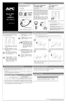
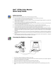
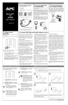
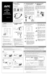
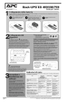
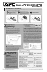
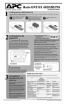
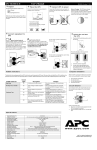
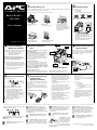
6HWXS
&RQQHFWEDWWHU\ZLUH
3ODFH3RZHU836
The UPS is shipped with one battery wire disconnected - in compliance with Department of Transportation
(DOT) regulations. Connect the battery wire as shown.
Place the UPS to avoid:
• Direct sunlight.
• Excessive heat.
• Excessive humidity or contact with liquids.
The UPS will not operate unless the steps below are performed.
Back-UPS Pro ®
350 / 500
Plug the UPS directly into a wall outlet.
a. Set the UPS at the edge
of a table.
User’s Manual
990-2052B Revision 3
5/99
d. Slide the battery back in.
Avoid pinching the wires.
b. Slide the battery
compartment cover down.
c. Grasp the tab attached to the
battery and slide the battery
partially out. Connect the black
wire to the battery by pushing it all
the way onto the terminal. Small
sparks are normal.
• The Building Wiring Fault indicator may flash
momentarily while being plugged in.
• The UPS begins charging when connected to
utility power.
• Four hours of charging should be sufficient to
achieve maximum battery capacity.
e. Slide the battery compartment
cover back into place.
Monitor
&KHFNWKH%XLOGLQJ
:LULQJ)DXOWLQGLFDWRU
&RQQHFWHTXLSPHQWWR
836
If the Building Wiring Fault indicator on the power
plug stays lit, one of the following conditions exist:
Do not plug surge protectors or power strips into
Battery Backup outlets.
• Open or high resistance ground.
• Hot and neutral polarity reversal.
• Overloaded neutral circuit.
A lit indicator means that a possible shock
hazard exists. Improper building wiring should
be corrected by a qualified electrician.
Note: Improper building wiring will not prevent the
UPS from operating, but will limit its protection
capability. Improper building wiring could result
in equipment damage that is not covered by
APC. Please refer to APC’s Equipment
Protection Policy for details.
Battery Backup Plus Surge Protection outlets (4)
Data sensitive equipment such as a computer,
monitor, and external drives should be powered by
these outlets. Battery power is automatically
provided in case of power outage. Power (utility or
battery) is not supplied to these outlets when the
UPS is switched Off.
Press the On/Test button.
&RQQHFW86%FDEOHDQG
LQVWDOOVRIWZDUH
RSWLRQDOSURFHGXUH
Your computer system must be On before starting
this procedure. Have your Windows 98 operating
system CD ready.
You will observe the following events after
pressing and releasing the On/Test button:
• The green On Line indicator will flash.
• The yellow On Battery indicator will light
while a battery test is performed.
• When the self test has successfully completed,
only the green On Line indicator will be lit.
• The red Overload indicator may flash briefly
when the UPS is switched on.
Following the test, if a red indicator is lit or you
want to perform a self test, consult the
troubleshooting section.
Connect the USB cable end, with USB symbol
facing down, to the UPS. Connect the other USB
cable end directly to an available USB port on your
computer.
&RQQHFWSKRQHFDEOHVWR
VXUJHSURWHFWLRQ
The UPS can protect up to two telephone lines on
one phone cable. Connect your modem/fax/phone
as shown with the release tab facing up for the
ends connected to the UPS.
Computer
Printer
Wall
Outlet
Surge Protection outlets (3)
Equipment such as a printer, fax machine, scanner,
or even a desk lamp should be powered by these
outlets. These outlets do not provide power during a
power outage. These outlets are always on (when
utility power is available) and are not controlled
by the front panel switches.
Transformer Block outlets (2)
One Battery Backup Plus Surge Protection and one
Surge Protection outlet accept transformer blocks.
6ZLWFK2Q7HVWWKH836
Fax
Scanner
External
Drive
Typical Installation
Black Velcro Cord Straps (2 - not shown)
Straps can be used to manage cords.
Modem/Fax/Phone
1.
6.
2.
After connecting the USB cable, the
Windows 98 "ADD NEW HARDWARE
WIZARD" dialog box is displayed. Insert
your Windows 98 operating system CD into
the computer’s CD-ROM drive before
proceeding.
If the software does not automatically install,
your Windows 98 auto run feature may have
been disabled.
To install:
Follow the installation instructions on your
computer screen.
a. Click “Start”.
b. Click “Run”.
c. Enter the path to the setup.exe file on
the CD-ROM drive:
CD-ROM drive letter:/setup.exe
d. Click “OK”.
During installation, Windows will need to
search for new drivers. When prompted,
make sure the CD-ROM drive box is checked.
3.
USB connection on rear panel of UPS:
After installation is complete, a "Windows 98
CD-ROM" dialog box may appear. If this
happens, just close the box.
4.
Remove the Windows 98 Operating System
CD from the CD-ROM drive.
5.
Insert the APC Power Management
Extensions for Windows 98 CD into the
computer’s CD-ROM drive.
The software user guide is a file on the CD.
Its filename is User’s Guide.pdf.
Follow the installation instructions on your
computer screen.
7.
After installation is complete, the APC plug
Task Bar icon will appear on your Task Bar
(near the clock). To start the Power
Management application Double-click on the
APC plug Task Bar icon or start the Power
Management applet in the Windows 98
control panel.
6WDWXV,QGLFDWRUV
There are four indicator lights and a speaker grille on the
front panel to indicate UPS status.
On Battery (yellow) - This indicator is lit
whenever utility power is outside safe limits and the
UPS battery is powering the Battery Backup outlets. If
the outage is extended, APC software can close
software applications, and then shut down the operating
system and the UPS.
Four Beeps Every 30 Seconds - This alarm is
sounded whenever the UPS is running On
On Line (green) - This indicator is lit whenever
conditioned utility power is powering the Battery
Backup outlets.
Single Beep - This alarm is sounded whenever
the On/Test button is pressed.
Overload (red) - This indicator is lit whenever
equipment connected to Battery Backup outlets is
drawing more power than the UPS can provide. Move
one or more pieces of equipment to the Surge
Protection outlets.
Continuous Tone - This alarm is sounded
whenever the Battery Backup outlets are
overloaded.
Battery.
Continuous Beeping - This alarm is sounded
whenever a low battery condition is reached.
Battery runtime is very low. Promptly save your data,
exit all applications, and then shut down the operating
system.
Circuit Breaker - The circuit
breaker button will stick out if
an overload condition forces
the UPS to disconnect itself
from utility power. If the
button sticks out, disconnect
non-essential equipment and reset the circuit breaker by
pushing the button in.
Replace Battery (red) - This indicator is lit
whenever the automatic diagnostic test has determined
the battery is near the end of its useful life. The battery
should be replaced within two weeks (see Order
Replacement Battery). Failure to replace the battery
may result in insufficient runtime during a power
outage.
Chirps for 1 Minute Every 5 Hours - This
alarm is sounded whenever the battery has
failed the automatic diagnostic test.
APC and Back-UPS Pro are registered trademarks of
American Power Conversion.
7URXEOHVKRRWLQJ
8366WRUDJH
Use the table below to solve minor UPS installation or operation problems. Consult APC Online Technical
Support or call APC Technical Support for assistance with problems that cannot be solved using the table below:
If the UPS needs to be stored for extended periods of time, the battery needs to be charged periodically to
maximize battery capacity. Before storing, charge the UPS for at least 10 hours. Store the UPS covered and
upright in a cool, dry location.
Possible Cause
Procedure
836ZLOOQRWWXUQRQ
Battery is not connected properly.
UPS not connected to AC power supply.
UPS circuit breaker “tripped”.
Very low or no utility voltage.
Utility overvoltage.
Extended Storage
Check the battery connections. Consult “Connect battery
wire” under “Setup” on the front page which shows how to
access the battery and connect the wire.
Check that the UPS power plug is securely connected to the
wall outlet.
Disconnect non-essential equipment from
the UPS. Reset the circuit breaker (on
back of UPS) by pushing the button back
in. If the breaker resets, switch the UPS
On and reconnect equipment one at a
time. If the breaker trips again it is likely
that one of the connected devices is
responsible for the overload.
Check the wall outlet, that supplies power
to the UPS, with a table lamp. If the lamp
is very dim, have the utility voltage
checked by a qualified electrician.
Connect the UPS to another wall outlet or have a qualified
electrician check the building wiring.
836RSHUDWHVRQEDWWHU\DOWKRXJKQRUPDOXWLOLW\YROWDJHH[LVWV
UPS’s circuit breaker “tripped”.
The specific wall outlet the UPS is
connected to does not supply utility
voltage.
Disconnect non-essential equipment from
the UPS. Reset the circuit breaker (on
back of UPS) by pushing the button back
in.
Connect the UPS to another wall outlet or have a qualified
electrician check the building wiring.
836GRHVQRWSURYLGHH[SHFWHGEDFNXSWLPH
The UPS is excessively loaded.
The UPS’s battery is weak due to recent
outage and has not had time to recharge.
Battery requires replacement.
Unplug non-essential Battery Back-Up connected
equipment, such as printers. They can be plugged into Surge
Protection outlets.
Note: Devices that have motors or dimmer switches (laser
printers, heaters, fans, lamps, and vacuum cleaners for
example) should not be connected to the Battery Backup
Plus Surge Protection outlets.
Charge the battery. The battery charges whenever it is
connected to utility power. Typically, six to eight hours are
needed to fully charge the battery from total discharge. UPS
runtime is reduced until the battery is fully charged. You can
perform a self test after the battery is fully recharged by
pressing and holding the On/Test button for more than 1
second, then releasing it.
If the Replace Battery LED is lit, the battery should be
promptly replaced. If the UPS is operated with a
weakened battery, runtime will be significantly reduced.
Battery capacity decreases with frequent power outages or
when the UPS is operated at elevated temperatures. Batteries
typically last 3-6 years.
$UHGLQGLFDWRULVOLWRUIODVKLQJ
The Overload indicator is lit if equipment
connected to Battery Backup outlets is
drawing more power than the UPS can
provide.
The Replace battery indicator is lit if the
battery is near the end of its useful life.
The On Line and Overload indicators are
flashing alternately.
Move one or more pieces of equipment to the Surge
Protection outlets.
The battery should be replaced within two weeks (see Order
Replacement Battery). Failure to replace the battery may
result in insufficient runtime during a power outage.
The UPS has entered sleep mode. This lasts for 16 seconds
during a power outage and is normal.
$OOLQGLFDWRUOLJKWVDUHIODVKLQJ
UPS failure
Call APC for service.
836GRHVQRWSRZHUWKH3&0RQLWRUGXULQJDQRXWDJH
Battery is not connected.
PC and/or monitor is plugged into a Surge
Protection outlet.
Check the battery connections. (See “Connect battery wire”
under “Setup” on the front page.)
Move PC and/or monitor to the Battery Backup plus Surge
Protection outlets.
Storage Temperature
5 to 86oF (-15 to 30oC)
86 to 113oF (30 to 45oC)
Recharge Frequency
Every 6 Months
Every 3 Months
Charging Duration
10 Hours
10 Hours
2UGHU5HSODFHPHQW%DWWHU\
The typical battery lifetime is 3-6 years (depending on number of discharge cycles and operating temperature). A
replacement battery can be ordered from local retailers, APC, or the APC web site.
The APC part number for the APC Back-UPS Pro (350 or 500) Replacement Battery Cartridge is RBC2.
%DWWHU\5HSODFHPHQW
Battery replacement is a safe procedure. You may leave the UPS On and equipment connected
during this procedure. Do not replace the battery when the UPS is On Battery.
Please consult the “Connect battery wire” diagrams (a through d) on the front page during this
procedure.
1. Set the UPS at the edge of a table (diagram a).
2. Slide the battery compartment cover down (diagram b).
3. Grasp the tab attached to the battery and slide the battery partially out. Then grab the battery firmly and pull it
out. The battery wires will disconnect as the battery is pulled out (diagram c).
4. Carefully insert the new battery halfway into the UPS, avoid pinching the wires (diagram d).
5. Connect the wires to the new battery:
Red wire - to red terminal
Black wire - to black terminal
Small sparks at the battery terminals are normal during connection.
6. Carefully insert the battery fully into the UPS (diagram d).
7. Slide the battery compartment cover back into place (diagram e).
The old battery must be recycled. Deliver the battery to an appropriate recycling facility or return it to APC in
the packing carton that came with your new battery. Additional recycling information is provided with your
new battery.
6HUYLFH
If the unit arrived damaged, notify the carrier.
If the UPS requires service, do not return it to the dealer. The
following steps should be taken.
1. Consult the Troubleshooting section to eliminate common problems.
2. Verify that the circuit breaker is not tripped. A tripped circuit breaker is the most common UPS problem.
3. If the problem persists, consult APC Online Technical Support or call APC Technical Support.
• When calling APC Technical Support, have the model number of the UPS, the serial number and
the date purchased ready. Be prepared to troubleshoot the problem over the telephone with an APC
Technical Support representative. If this is not successful, APC will issue a Return Merchandise
Authorization number (RMA#) and a shipping address.
• A UPS under warranty will be repaired at no cost.
The standard warranty is 2 years from date of purchase. APC's standard procedure will be to replace
the original unit with a factory reconditioned unit. APC will ship out the replacement unit once the
defective unit has been received by the repair department or cross ship upon the receipt of a valid
credit card number. The customer pays for the shipping to APC and APC pays ground freight
transportation costs back to the customer.
• Customers who must have the original unit back due to assigned asset tags and set depreciation
schedules must declare such a need at first contact with an APC Technical Support representative.
• If the warranty has expired, there is a repair charge.
4. For Return:
• Disconnect the black wire from the UPS battery. Department of Transportation (DOT) regulations
require that the black battery wire be disconnected before shipping the UPS back to APC. Refer to
“Connect battery wire” instructions and graphics on the front page for how to disconnect the black
wire from the battery.
• Pack the UPS in its original packaging. If the original packing is not available, contact APC
Technical Support to obtain a new set. Pack the UPS properly to avoid damage in transit.
Never use Styrofoam™ beads for packaging. Damage sustained in transit is not covered
under warranty (insuring the package for full value is recommended).
• Write the RMA# on the outside of the package.
• Return the UPS by insured, prepaid carrier to the address given to you by Technical Support.
6SHFLILFDWLRQV
Acceptable Input Voltage
Input Voltage (on line)
Output Voltage
Frequency Limits (on line)
Maximum Load
Typical Recharge Time
Operating Temperature
Storage Temperature
Operating and Storage Relative
Humidity
Size (H x W x D)
Weight
Shipping Weight
EMI Classification
The recommended period of time the unit can be stored without periodic charging is dependent on the
storage temperature:
0 - 160 Vac, Single Phase
90 - 133 Vac
103 -133 Vac
47 - 63 Hz (autosensing)
350 VA - 220 W
500 VA - 315 W
6 to 8 hours from total discharge
32 to 104°F (0 to 40°C)
5 to 113°F (-15 to 45°C)
0 to 95%, non-condensing
9.4 x 5.0 x 7.9 in (23.9 x 12.7 x 20.0 cm)
350 VA -14.2 lb (6.4 kg)
500 VA - 15.4 lb (6.9 kg)
350 VA - 16.2 lb (7.4 kg)
500 VA - 17.8 lb (8.1 kg)
FCC/DOC Class B certified
Note: Detailed UPS product specifications are available online at the APC web site or through the APC
faxback system ( 800-347-3299).
$3&&RQWDFW,QIRUPDWLRQ
USA/Canada …………….
Mexico……………………
Brazil …………………….
Worldwide ………………
1.800.800.4272
292.0253 / 292.0255
0800.12.72.1
1.401.789.5735
Web site……………………http://www.apcc.com
Online Technical Support…http://support.apcc.com