1
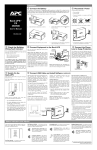
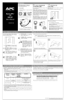
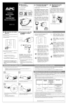
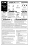
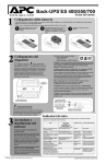
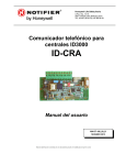
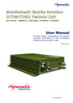
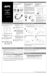
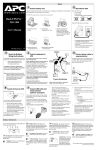
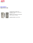
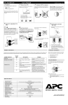
Installation
2 Placement / Power
1 Connect the Battery
®
®
In compliance with Department of Transportation (DOT) regulations, the Back-UPS is shipped with the
internal red battery wire disconnected. The Back-UPS will not operate until the internal red wire is connected to the battery. Once connected, allow the Back-UPS to charge for a full eight hours prior to use.
Avoid placing the Back-UPS in:
• Direct sunlight
• Excessive heat
Note: Small sparks may occur during battery connection. This is normal.
• Excessive humidity or in contact with fluids
of any type
w w w.apc.com
Back-UPS™
RS 500
Plug the Back-UPS into a wall outlet, as shown.
a.
Open the battery compartment, as shown.
c.
Connect the red battery wire to the
battery terminal.
b.
Pull the battery about half way out, as shown
d.
Push the battery into the battery compartment
and re-install the cover, as shown.
User’s Manual
positive
990-2204
3 Check the Building
Wiring Fault Indicator
If the red Building Wiring Fault indicator on the
rear panel of the Back-UPS is lit, one of the
following conditions exists:
• Open or high resistance ground
• Hot or neutral polarity reversed
• Overloaded neutral circuit
A lit indicator means that a potential shock
hazard exists. Improper building wiring should
be corrected by a qualified electrician. Do not
use the Back-UPS until the condition that caused
the fault is corrected.
Note: Improper building wiring will not prevent the
Back-UPS from operating, but it will limit its
protection capability. It may also result in
equipment damage that is not covered by the APC
Equipment Protection Policy.
6 Switch On the
Battery Back Up Outlets (qty. of 3). These
outlets provide battery back-up, surge protection,
and Electro-magnetic Interference (EMI) filtering.
In case of power outage, battery power is
automatically provided to these outlets. Power
(utility or battery) is not supplied to these outlets
when the Back-UPS is switched Off. Connect a
computer, monitor, and external disk or CD-ROM
drive to these outlets.
Line to Surge Protection
Fax
Monitor
Computer
Printer
External
Drive
The telephone ports provide lightning surge protection for any device connected to the telephone
line (computer, modem, fax or telephone). The
telephone ports are compatible with Home Phoneline Networking Alliance (HPNA) and Digital
Suscriber Line (DSL) standards, as well as all
modem data rates. Connect as shown.
Wall Outlet
Scanner
Surge Only Outlets (qty. of 3). These outlets are
always On (when utility power is available) and
are not controlled by the On/Off switch. These
outlets do not provide power during a power
outage. Connect a printer, fax machine or scanner
to these outlets.
Black Velcro Straps (qty. of 2 - not shown). For
convenience, two velcro traps have been included
and can be used to manage power cords.
Modem/Phone/Fax
Transfer Voltage Adjustment (optional)
7 Connect USB Cable and
In situations where the Back-UPS or connected equipment appears too sensitive to
input voltage, it may be necessary to adjust the transfer voltage. This is a simple task
requiring use of the front panel pushbutton. To adjust the transfer voltage, proceed as
follows:
1. Plug the Back-UPS into the utility power source. The Back-UPS will be in a
Standby Mode (no indicators lit).
2. Press the front panel pushbutton fully inward for 10 seconds. All indicators on the
Back-UPS will flash to acknowledge going into Programming Mode.
3. The Back-UPS will then indicate its current Sensitivity Setting, as shown in the
following table.
Install Software (optional)
Back-UPS
5 Connect the Phone
4 Connect Equipment to the Back-UPS
The rear panel of the Back-UPS consists of the
following elements:
• The Back-UPS charges the internal battery
any time it is connected to a wall outlet.
Note: Allow the Back-UPS to charge for a full eight
hours prior to use.
Press the push-button on the front panel of the
Back-UPS.
TO COMPUTER
USB PORT
RJ-45 to USB
CABLE
On Line
On Battery
Overload
Indicators
Flashing
Sensitivity
Setting
Input Voltage
Range
(for utility
operation)
Use When
1
(yellow)
Low
78 - 150 Vac
Input voltage is extremely low
or high. Not recommended for
computer loads.
2
(yellow, and
red)
Medium
(factory default)
83 - 147 Vac
Back-UPS frequently goes On
Battery.
3
(yellow, red,
and red)
High
88 - 144 Vac
Connected equipment is
sensitive to voltage
fluctuations (recommended).
Replace Battery
If Autoplay is not enabled on the computer, proceed as follows:
1. On the computer desktop of the display, double-click on My
Computer.
2. Double-click on the CD-ROM drive icon and follow the onscreen instructions.
Observe that the following events occur after
pressing and releasing the push-button:
Follow the
on-screen
instructions.
• The green On-Line indicator flashes.
• The yellow On Battery indicator lights while
the Self-Test is being performed.
4. To select the Low Sensitivity setting, press the pushbutton until the yellow indicator
is flashing.
5. To select the Medium Sensitivity setting, press the pushbutton until the yellow and
red indicators (second and third from the top) are flashing.
6. To select the High Sensitivity setting, press the pushbutton until yellow and both
red indicators (bottom three) are flashing.
7. To exit without changing the Sensitivity Setting, press the pushbutton until the
green indicator is flashing.
8. Once in Programming Mode, if the pushbutton is not pressed within 5 seconds, the
Back-UPS will exit Programming Mode; all indicators will extinguish.
• When Self-Test has successfully completed,
only the green On Line indicator will be lit.
• If the internal battery is not connected, (see
Step 1 above) the green On Line indicator and
red Replace Battery indicator will light. The
Back-UPS will also emit a chirping sound.
Status Indicators and Alarms
There are four status indicators (lights) on the front
panel of the Back-UPS (On Line, On Battery,
Overload, and Replace Battery).
On Line
On Battery (yellow) - is lit whenever the battery of the Back-UPS is powering equipment connected to the Battery Backup Outlets.
Four Beeps Every 30 Seconds - this
alarm is sounded whenever the BackUPS is running On Battery. Consider
saving work in progress.
Overload (red) - is lit whenever power demand
has exceeded the capacity of the Back-UPS.
Continuous Tone - this alarm is
sounded whenever the Battery Backup
outlets are overloaded.
On Battery
Overload
Replace Battery
On Line (green) - is lit whenever utility power
is powering the Battery Backup outlets.
Continuous Beeping - this alarm is
sounded whenever a low battery condition is reached. Battery run-time is
very low. Promptly save any work in
progress and exit all open applications. Shutdown the operating system,
computer and the Back-UPS.
Circuit Breaker - the circuit breaker
button located on the rear panel of the
Back-UPS will stick out if an overload
condition forces the Back-UPS to disconnect itself from utility power. If the
button sticks out, disconnect non-essential equipment. Reset the circuit breaker
by pushing the button inward.
Replace Battery (red) - is lit whenever the battery is near the end of its useful life, or if the battery is not connected (see above). A battery that is
near the end of its useful life has insufficient runtime and should be replaced.
Chirps for 1 Minute Every 5 Hours this alarm is sounded whenever the
battery has failed the automatic diagnostic test.
Copyright © 2004 American Power Conversion. All rights reserved.
APC and Back-UPS are registered trademarks of American Power Conversion.
All other trademarks are property of their respective owners.
Troubleshooting
Back-UPS Storage
Use the tables below to solve minor Back-UPS installation and operation problems. Consult APC On-line
Technical Support or call APC Technical Support for assistance with problems that cannot be resolved using
this document:
Before storing, charge the Back-UPS for at least eight hours. Store the Back-UPS covered and upright in
a cool, dry location. During storage, recharge the battery in accordance with the following table:
Storage Temperature
Possible Cause
23o to 86oF (-5o to 30oC)
Procedure
Back-UPS will not switch on
Back-UPS not connected to an AC
power source.
Check that the Back-UPS power plug is
securely connected to the wall outlet.
Recharge Frequency Charging Duration
Every 6 months
8 hours
86o to 113oF (30o to 45oC) Every 3 months
8 hours
Please contact APC Technical Support to troubleshoot the unit before returning it to APC.
Order Replacement Battery
Back-UPS circuit breaker “tripped”.
Very low or no utility voltage.
Disconnect non-essential equipment from the
Back-UPS. Reset the circuit breaker (located
on the rear panel of the Back-UPS) by pushing the circuit breaker button fully inward
until it catches. If the circuit breaker resets,
switch the Back-UPS on and reconnect the
equipment one-at-a-time. If the circuit
breaker trips again, it is likely that one of the
connected devices is causing the overload.
Check the wall outlet that supplies power to
the Back-UPS using a table lamp. If the lamp
bulb is very dim, have the utility voltage
checked by a qualified electrician.
Back-UPS does not power computer/monitor/external drive during an outage
Internal battery is not connected.
Check the battery connections. (See “Connect the Battery” under
“Installation” on the front page of this document.
Computer, monitor or external disk/
CD-ROM drive is plugged into a
Surge Only outlet.
Move computer, monitor, or external drive power cord plug to the
Battery Backup outlets.
Back-UPS operates on battery although normal utility voltage exists
Back-UPS circuit breaker “tripped”.
Disconnect non-essential equipment from the
Back-UPS. Reset the circuit breaker (located
on the rear panel of the Back-UPS) by pushing the circuit breaker button fully inward
until it catches.
The wall outlet that the Back-UPS is Connect the Back-UPS to another wall outlet or have a qualified
connected to does not supply utility electrician check the building wiring.
power to the unit.
Back-UPS does not provide expected backup time
Back-UPS is excessively loaded.
Unplug non-essential Battery Backup connected equipment, such as
printers and plug them into Surge Only outlets.
Note: Devices that have motors or dimmer switches (laser printers,
heaters, fans, lamps, and vacuum cleaners, for example) should not be
connected to the Battery Backup outlets.
The typical battery lifetime is 3-6 years (depending on the number of discharge cycles and operating
temperature). A replacement battery can be ordered over the phone from APC, or the battery can be
ordered on-line from the APC web site (see below, a valid credit card is required).
When ordering, please specify Battery Cartridge RBC2.
Battery Replacement
Battery replacement is a safe procedure. The Back-UPS can be left on with the equipment connected
during this procedure. Do not replace the battery when the Back-UPS is On Battery. Refer to the APC
Safety Guide for additional information.
Please consult the "Connect Battery" diagrams (a through d) on the front page of this document when
performing the following procedures:
1.
2.
3.
4.
5.
6.
7.
8.
9.
10.
11.
12.
While viewing the Back-UPS from the front, lay the Back-UPS on its left side (diagram a).
Slide the battery compartment cover off of the Back-UPS (diagram a).
Grasp the tab attached to the battery and slide the battery partially out of the case. Grab the battery
firmly and pull it straight out. The battery wires will disconnect as the battery is pulled out (diagram b).
Carefully unpack the new battery. Retain the packing carton so that the old battery can be recycled.
Insert the new battery halfway into the Back-UPS (diagram d).
Connect the wires to the new battery as follows:
Red Wire - to red (positive) terminal
Black Wire - to black (negative) terminal
Note: Small sparks at the battery terminals are normal during connection.
Carefully insert the battery fully into the Back-UPS.
Slide the battery compartment cover back into place.
The Replace Battery indicator will shut off within the 14-day self-test interval, or when the BackUPS is switched On.
The old battery must be recycled. Deliver the battery to an appropriate recycling facility or return it to
APC in the packing carton that came with the new battery. Additional recycling information is provided
with the new battery.
Service
Back-UPS battery is weak due to
recent outage and has not had time
to recharge.
Charge the battery. The battery charges whenever the Back-UPS is
connected to a wall outlet. Typically, eight hours of charging time are
needed to fully charge the battery from total discharge. Back-UPS
run-time is reduced until the battery is fully charged.
If the Back-UPS arrived damaged, notify the carrier.
Battery requires replacement.
Replace battery (see Order Replacement Battery). Batteries typically
last 3-6 years, shorter if subjected to frequent power outages or elevated temperatures.
1.
2.
A red indicator is lit
Battery is not connected properly.
Check the battery connections. Consult "Connect the Battery" under
"Installation" on the front page of this document. It shows how to
access the battery and connect the wires.
The Overload indicator is lit if
equipment connected to the Battery
Backup outlets is drawing more
power than the Back-UPS can provide.
Move one or more equipment power plugs to the Surge Only outlets.
Battery requires replacement.
The battery should be replaced within two weeks (see "Order
Replacement Battery"). Failure to replace the battery will result in
reduced run-time during a power outage.
Red indicators are flashing
Back-UPS failure.
Call APC for service.
Replace Battery indicator lit and an alarm sounds when the Back-UPS is turned on
Internal battery not connected.
Check the battery connections. Consult "Connect the Battery" under
"Installation" on the front page of this document. It shows how to
access the battery and connect the wires.
Specifications
Input Voltage (on line)
Frequency Limits (on line)
On Battery Waveshape
Maximum Load
Consult the Troubleshooting section to eliminate common problems.
Verify that the circuit breaker is not tripped. A tripped circuit breaker is the most common BackUPS problem.
3.
If the problem persists, consult APC On-line Technical Support or call APC Technical Support (see
below).
• When calling APC Technical Support, have the Back-UPS model number, serial number and date
of purchase available. Be prepared to troubleshoot the problem over the phone with an APC Technical Support representative. If this is not successful, APC will issue a Return Merchandise Authorization (RMA) number and a shipping address.
• A Back-UPS under warranty will be repaired at no cost. The standard warranty is two (2) years
from the date of purchase. APC’s standard procedure will be to replace the original unit with a factory reconditioned unit. APC will ship the replacement unit once the defective unit has been
received by the repair department, or cross ship upon the receipt of a valid credit card number. The
customer pays for shipping the unit to APC. APC pays ground freight transportation costs to ship
the replacement to the customer.
• Customers who must have the original unit back due to assigned asset tags and set depreciation
schedules must declare such a need at first contact with an APC Technical Support representative.
• If the warranty has expired, there is a repair charge.
For return:
• Disconnect the red battery terminal wire from the Back-UPS battery (see "Connect the Battery"
instructions and graphics on the front of this document). Department of Transportation (DOT) regulations require that the battery wire be disconnected before shipping the Back-UPS to APC.
• Pack the Back-UPS in its original packaging. If the original container is not available, contact APC
Technical Support to obtain a new set. Pack the Back-UPS properly to avoid damage in transit.
• Never use styrofoam beads for packaging. Damage sustained in transit is not covered under the
warranty (insuring the package for full value is recommended).
• Write the RMA number on the outside of the package.
• Return the Back-UPS to APC by insured, prepaid carrier to the address provided by APC Technical Support.
78 - 150 Vac
47 - 63 Hz (autosensing)
Stepped Sine Wave
500 VA - 300 W
Typical Recharge Time
8 Hours
Operating Temperature
32o to 104oF (0o to 40oC)
Storage Temperature
23o to 113oF (-5o to 45oC)
Operating and Storage
Relative Humidity
0 to 95% non-condensing
Size (H x W x D)
If the Back-UPS requires service, do not return it to the dealer. The following steps should be
taken:
6.5 x 3.6 x 11.2 inches
Warranty
The standard warranty is two (2) years from the date of purchase. APC’s standard procedure is to replace
the original unit with a factory reconditioned unit. Customers who must have the original unit back due
to assigned asset tags and set depreciation schedules must declare such a need at first contact with an
APC Technical Support representative. APC will ship the replacement unit once the defective unit has
been received by the repair department, or cross ship upon the receipt of a valid credit card number. The
customer pays for shipping the unit to APC. APC pays ground freight transportation costs to ship the
replacement to the customer.
APC Contact Information
(16.5 x 9.2 x 28.5 cm)
Weight
500 VA - 13.8 lb (6.3 kg)
USA/Canada
1.800.800.4272
Shipping Weight
500 VA - 15.3 lb (7.0 kg)
Mexico
292.0253 / 292.0255
FCC/DOC Class B Certified
Brazil
0800.12.72.1
Worldwide
1.401.789.5735
Internet
http:\\www.apc.com
Technical Support
http:\\www.apc.com/support
EMI Classification
On Battery Run-Time
20 Minutes typical - desktop computer and 15 inch (38.1 cm) monitor.
FCC Notice
FCC Part 68, FCC Part 15 Class B
Notice: This device complies with part 15 of the FCC rules. Operation
is subject to the following two conditions: (1) This device may not
cause harmful interference, and (2) This device must accept any
interference received, including interference that may cause undesired
operation. This equipment complies with Part 68 of the FCC rules. on
the bottom of this equipment is a label that contains, among
other information, the FCC registration number and ringer
equivalence number (REN) for this equipment. If requested,
this information must be provided to the telephone company.
Copyright © 2004 American Power Conversion. All rights reserved.