1
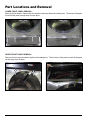
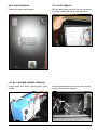
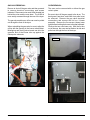
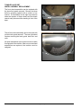
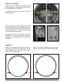
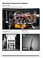
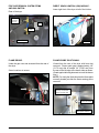
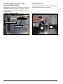
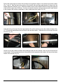
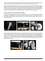
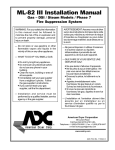
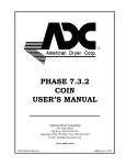
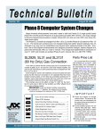
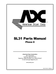
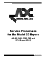
Service Procedures for the Model 20 Dryers (AD-20, SL20, CG20, D20, and STI-8 Dryers GEN II) ADC Part No. 450261 Retain This Manual in a Safe Place for Future Reference This product embodies advanced concepts in engineering, design, and safety. If this product is properly maintained, it will provide many years of safe, efficient, and trouble free operation. Only qualified technicians should service this equipment. OBSERVE ALL SAFETY PRECAUTIONS displayed on the equipment or specified in the installation manual included with the dryer. The following “FOR YOUR SAFETY” caution must be posted near the dryer in a prominent location. FOR YOUR SAFETY POUR VOTRE SÉCURITÉ Do not store or use gasoline or other flammable vapors and liquids in the vicinity of this or any other appliance. Ne pas entreposer ni utiliser d’essence ni d’autres vapeurs ou liquides inflammables à proximité de cet appareil ou de tout autre appareil. We have tried to make this manual as complete as possible and hope you will find it useful. The manufacturer reserves the right to make changes from time to time, without notice or obligation, in prices, specifications, colors, and material, and to change or discontinue models. The illustrations included in this manual may not depict your particular dryer exactly. IMPORTANT For your convenience, log the following information: DATE OF PURCHASE __________________________________________________ MODEL NO. ________________________ RESELLER’S NAME ______________________________________________________________________________________ SERIAL NUMBER(S) ______________________________________________________________________________________ _______________________________________________________________________________________________________ _______________________________________________________________________________________________________ Replacement parts can be obtained from your reseller or the ADC factory. When ordering replacement parts from the factory, you can FAX your order to ADC at (508) 678-9447 or telephone your order directly to the ADC Parts Department at (508) 678-9000. Please specify the dryer model number and serial number in addition to the description and part number, so that your order is processed accurately and promptly. IMPORTANT NOTE TO PURCHASER Information must be obtained from your local gas supplier on the instructions to be followed if the user smells gas. These instructions must be posted in a prominent location near the dryer. IMPORTANT You must disconnect and lockout the electric supply and the gas supply or the steam supply before any covers or guards are removed from the machine to allow access for cleaning, adjusting, installation, or testing of any equipment per OSHA (Occupational Safety and Health Administration) standards. Please observe all safety precautions displayed on the equipment and/or specified in the installation manual included with the dryer. Table of Contents Part Locations and Removal ................ 4 Lower Front Panel Removal ......................................... 4 Upper Front Panel Removal ......................................... 4 Back Guard Removal ................................................... 5 Top Cover Removal ....................................................... 5 Lint Box / Blower Assembly Removal ........................... 5 Gas Valve Removal ...................................................... 7 Oven Removal .............................................................. 7 CAUTION Dryer(s) should never be left unattended while in operation. “Caution: Label all wires prior to disconnection when servicing controls. Wiring errors can cause improper operation.” «Attention: Lor des opérations d’entretien des commandes étiqueter tous fils avant de les déconnecter. Toute erreur de câblage peut étre une source de danger et de panne.» Tumbler Support Wheel Assembly Replacement ......... 8 Tumbler Alignment ....................................................... 9 Electrical Component Locations ........ 10 Electrical Panel ......................................................... 10 Oven Contactor .......................................................... 10 Door Switch ............................................................... 10 Fire Suppression System Items and Sail Switch ........ 11 Direct Spark Ignition (DSI) Module .............................. 11 Flame-Probe ............................................................... 11 WARNING Children should not be allowed to play on or near the dryer(s). Children should be supervised if near dryer(s) in operation. Under no circumstances should the dryer door switch(es), lint door/drawer switch(es), or heat safety circuit(s) ever be disabled. The dryer must never be operated with any of the back guards, outer tops, or service panels removed. Personal injury or fire could result. The dryer must never be operated without the lint filter/screen in place, even if an external lint collection system is used. FOR YOUR SAFETY Do not dry mop heads in the dryer. Do not use dryer in the presence of dry cleaning fumes. The dryers must not be installed or stored in an area where it will be exposed to water and/or weather. The wiring diagram for the dryer is located in the front electrical control box area. Flame-Probe Positioning ............................................. 11 Exhaust Probe, Exhaust Hi-Limit, and Lint Drawer Switch ........................................................................ 12 Rotation Switch ......................................................... 12 Belt Installation ................................... 13 Placing the Belt Back on the Motor Sheave ............... 15 Part Locations and Removal LOWER FRONT PANEL REMOVAL: Remove the lint drawer. Remove the four screws located just below the loading door. Tilt the top of the panel out and lift the panel up and away from the dryer. UPPER FRONT PANEL REMOVAL: Remove the four screws located just above the loading door. Tilt the bottom of the panel out and lift the panel up and away from the dryer. 4 American Dryer Corp. 450261-2 BACK GUARD REMOVAL: TOP COVER REMOVAL: Remove all facing visible screws. With the back guard removed, the top is removed by pulling it toward the rear of the dryer and up. LINT BOX / BLOWER ASSEMBLY REMOVAL: Unplug wires from Direct Spark Ignition (DSI) module. 450261-2 Remove screws and nuts at the rear of the lint box. Unplug wires from the capacitor. www.amdry.com 5 LINT BOX / BLOWER ASSEMBLY REMOVAL (continued): Remove two screws just above the lint drawer. Pull the lint box down from the front and out slightly. Unplug three connections at the left of the lint box. The lint box may now be pulled out through the front of the dryer. To remove motorized impellor assembly, remove five screws and four nuts shown at the arrows. Lift off cover and pull motorized impellor assembly out through the opening. 6 American Dryer Corp. 450261-2 GAS VALVE REMOVAL: OVEN REMOVAL: Be sure to shut off the gas main and then proceed to remove electrical connections and screws indicated. Disconnect union and U-Bolt located just behind the union and the oven base. The U-Bolt is more easily accessed through the rear of the dryer. The oven can be removed with or without the gas valve in place. The gas valve and burner orifice can now be pulled out through the front of the dryer. When reinstalling the gas valve be sure to align the orifice with the opening in the burner tube bracket. Misaligning and forcing valve inward can drive the opposite end of the burner tube up against the flame-probe elements. Be sure to shut off the gas supply to the dryer. The back guard, heat duct, and lower front panel must be removed. Remove the gas valve electrical connections and remove the lint box / blower assembly. Remove the five screws (shown lower right) that are holding the burner to the rear bulkhead. Remove the two oven base nuts. With the lint box out of the way, the oven can be tilted on its side and pulled out through the front of the dryer. Heat Duct 450261-2 www.amdry.com 7 TUMBLER SUPPORT WHEEL ASSEMBLY REPLACEMENT: The front wheel assemblies can be replaced with the lower front panel removed. Remove the three bolts by reaching upward with a socket or box wrench. The illustration on the right is provided to show the location of these wheels as the wheels cannot easily be seen while standing in front of the dryer. The left rear wheel assembly can be removed with just the back guard removed. The rear right wheel requires removing the back guard, heat duct, and oven. All wheel assemblies are mounted on slots to allow for alignment of the tumbler. After one or more wheel assemblies are replaced, the tumbler must be realigned. 8 American Dryer Corp. 450261-2 TUMBLER ALIGNMENT: Proper alignment is achieved by making the gap between the tumbler and openings in the front and rear bulkheads equal on all sides. The gap may be checked for accuracy by using a thickness gauge. Adjust the tumbler position by loosening the three bolts and forcing the wheel assembly toward the center of the dryer to raise the tumbler and to move it away from the side. A large screwdriver can provide the necessary leverage. Adjustment of the front of the tumbler is made the same as the rear. The gap on the top, bottom, left and right are to be made equal by moving the wheel assemblies. EXAMPLES: Below, both wheel assemblies must be moved to the right in order to move the tumbler right. The left wheel assembly must move a little more than the right in order to lift the tumbler. 450261-2 Below, both wheel assemblies must be moved inward in order to move the tumbler straight upward. www.amdry.com 9 Electrical Component Locations ELECTRICAL PANEL: The electrical panel is located behind the front upper panel. F1 J11 P14 Terminal Block A B C Relay 3 Relay 2 Relay 1 Drive Blower Door Switch Transformer 25VAC J5 OVEN CONTACTOR: DOOR SWITCH: Lower right front of the dryer (electric oven models). On upper front panel. Oven Contactor Door Switch 10 American Dryer Corp. 450261-2 DIRECT SPARK IGNITION (DSI) MODULE: FIRE SUPPRESSION SYSTEM ITEMS AND SAIL SWITCH: Lower right front of the dryer to left of the lint box. Rear of the dryer. Water Pressure Switch Sail Switch Solenoid Valve Thermistor Probe DSI Module FLAME-PROBE: FLAME-PROBE POSITIONING: Under the gas oven and accessed from the rear of the dryer. Viewed from the rear of the dryer with heat duct removed. Proper spark gap is approximately 1/8” (3.175 mm) and is located 1/4” (6.325 mm) from the rear of the left edge of the burner tube as shown. (Guard against allowing elements to touch the burner tube.) NOTE: For clarity the illustration has the flame plate normally located just after the flame sensing probe removed. Screw locations at arrows. Flame-probe spark gap directly over the left edge of burner tube Flame-probe element as shown Correct positioning of the flame-probe elements. 450261-2 www.amdry.com 11 EXHAUST PROBE, EXHAUST HI-LIMIT, AND LINT DRAWER SWITCH: ROTATION SWITCH: Temperature probe and exhaust hi-limit are accessible once the lint box is removed. The lint drawer switch can be removed after the cover has been removed. Just behind the upper front panel, as viewed from the rear of the dryer with top removed. Exhaust Hi-Limit Switch Exhaust Temperature Probe Lint Drawer Switch 12 Rotation Switch Magnet American Dryer Corp. Rotation Switch 450261-2 Belt Installation REQUIRED ITEMS: 4 feet of Number 16 or 18 Electrical Wire Duct Tape Phillips Screw Driver 5/16” Nut Driver Electrical Tape 3 foot Section of 1-1/2” Electrical Tubing One 6-inch Cable Tie Replacement Belt Remove the back guard, front upper panel, and front lower panel. Cut the locking end off the plastic wire tie and use a piece of electrical tape to secure the wire tie to one end of the 4-foot section of electrical wire (Fig. 1). FIG. 2 FIG. 1 FIG. 3 Push the wire tie between the tumbler felt and the middle front panel ring at highest position of the tumbler (Fig. 2). The wire tie must exit beyond the top of the tumbler (Fig. 3). Be careful NOT to damage the rotational sensor. Take hold of the end of the wire tie, pull it and the electrical wire attached to it until 2 feet of wire remains hanging inside the tumbler (Fig. 4). Attach the replacement belt to the end of the electrical wire still hanging in the tumbler by making a loop in the wire and taping the loop closed with electrical tape (Fig. 5). Squeeze the belt flat between your fingers (Fig. 6). FIG. 5 FIG. 4 450261-2 www.amdry.com FIG. 6 13 Pull the belt up through the tumbler felt until there is enough belt to begin to loop the belt around the tumbler (Fig. 7 and 8). Tape the belt to the outside of the tumbler with duct tape approximately 2-inches from the outside edge of the tumbler (Fig. 9). Rotate the tumbler slowly in the clockwise direction, while pulling the end of the belt to the right side of the dryer. Continue to rotate the tumbler clockwise and proceed to tape the belt to the outside of the tumbler occasionally, to aid in holding the belt in place (Fig. 10). FIG. 8 FIG. 7 FIG. 9 Guide the belt over the top of the front right tumbler roller, while continuing to turn the tumbler clockwise (Fig. 11). The end will pass between the top of the lint box and the tumbler. Guide the belt over the top of the front left roller (Fig. 12). FIG. 11 FIG. 10 FIG. 12 Continue to turn the tumbler clockwise while feeding the belt out of the tumbler, until only a few inches are left in the tumbler. Pull the remaining belt out of the tumbler into the area above the tumbler, until only a few inches remain in the tumbler (Fig. 13). FIG. 13 14 American Dryer Corp. FIG. 14 450261-2 Pulling the belt through the tumbler felt gap will tend to flip the felt. Before pulling the last few inches out of the tumbler, lace the electrical wire back through the loop in the belt (Fig. 13 on the previous page). Pull the remaining belt and a couple of inches of wire out of the tumbler and into the area above the tumbler. Slide the belt to the middle of the tumbler. With the electrical wire pulled tight (Fig. 14 on the previous page), rotate the tumbler one or two turns. This should flip the felt back to the original position. Feeling that the felt is even all the way around the tumbler indicates the felt is back to original position. Remove the electrical wire. The belt is now wrapped around the tumbler and ready for installation on the drive motor sheave. PLACING THE BELT BACK ON THE MOTOR SHEAVE: One proven method used to pull the belt back onto the sheave involves using a two foot length of electrical conduit (Fig. 15). Preparing the end of the conduit as shown makes it easier to use. Position the belt around the tumbler and directly above the motor sheave (Fig. 16). Insert the conduit through the belt and onto the motor sheave (Fig. 17). FIG. 16 FIG. 15 FIG. 17 While pushing the electrical tubing, pull the end toward the bottom right corner (Fig. 19). From this position, rotate the conduit clockwise. The belt will move to a position over the motor sheave. Hold the belt against the motor (Fig. 18). Rotate the conduit one more revolution while pulling the conduit out. The belt should drop onto the motor sheave. Rotate the tumbler a few turns while manually preventing the belt from falling off the sheave (Fig. 19). This should center the belt on the tumbler and prevent the belt from being thrown off later. Replace all dryer panels. FIG. 18 450261-2 www.amdry.com FIG. 19 15 ADC Part No. 450261 2 - 09/15/05 - 1