1
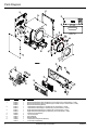
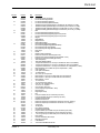
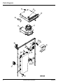
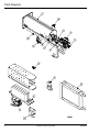
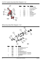
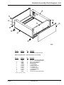
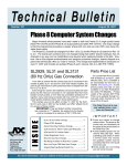
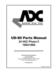
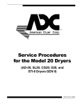
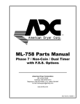
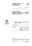
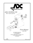
SL31 Parts Manual
Phase 8
American Dryer Corporation
88 Currant Road
Fall River, MA 02720-4781
Telephone: (508) 678-9000 / Fax: (508) 678-9447
E-mail: [email protected]
www.amdry.com
ADC Part No. 450282 - 5
Retain This Manual
In A Safe Place For Future Reference
This product embodies advanced concepts in
engineering, design, and safety. If this product
is properly maintained, it will provide many years
of safe, efficient, and trouble free operation.
ONLY properly licensed technicians should service this equipment.
OBSERVE ALL SAFETY PRECAUTIONS displayed on the equipment
or specified in the installation manual included with the dryer.
The following “FOR YOUR SAFETY” caution must be posted
near the dryer in a prominent location.
FOR YOUR SAFETY
POUR VOTRE SÉCURITÉ
Do not store or use gasoline
or other flammable vapors
and liquids in the vicinity of
this or any other appliance.
Ne pas entreposer ni utiliser d’essence
ni d’autres vapeurs ou liquides
inflammables à proximité de cet
appareil ou de tout autre appareil.
We have tried to make this manual as complete as possible and hope you will find
it useful. The manufacturer reserves the right to make changes from time to time,
without notice or obligation, in prices, specifications, colors, and material, and to
change or discontinue models.
Important
For your convenience, log the following information:
DATE OF PURCHASE _____________________________________________________
SL31
MODEL NO. _____________
RESELLER’S NAME _________________________________________________________________________________
Serial Number(s) ___________________________________________________________________________________
___________________________________________________________________________________________________
___________________________________________________________________________________________________
Replacement parts can be obtained from your reseller
or the ADC factory. When ordering replacement parts from
the factory, you can FAX your order to ADC at (508) 678-9447
or telephone your order directly to the ADC Parts Department
at (508) 678-9000. Please specify the dryer model number
and serial number in addition to the description and part number,
so that your order is processed accurately and promptly.
The illustrations on the following pages may not depict
your particular dryer exactly. The illustrations are a composite
of the various dryer models. Be sure to check the
descriptions of the parts thoroughly before ordering.
“IMPORTANT NOTE TO PURCHASER”
Information must be obtained from your local gas supplier
on the instructions to be followed if the user smells gas.
These instructions must be posted in a prominent location
near the dryer.
NOTES _______________________________________________________________________
______________________________________________________________________________
______________________________________________________________________________
______________________________________________________________________________
______________________________________________________________________________
______________________________________________________________________________
______________________________________________________________________________
______________________________________________________________________________
______________________________________________________________________________
______________________________________________________________________________
______________________________________________________________________________
______________________________________________________________________________
______________________________________________________________________________
______________________________________________________________________________
______________________________________________________________________________
Parts Diagram
Illus. No.
Part No.
Qty.
1
818925
818683
819622
819619
818679
819621
818678
818690
150445
153072
318891
153048
102373
1
1
1
1
1
1
1
1
2
2
1
1
1
2
3
4
5
6
7
8
4
Description
Back Guard Assembly (Gas and Electric) (For models mfd. as of December 7, 2005)
Back Guard Assembly (Gas and Electric) (For models mfd. prior to December 7, 2005)
Back Guard Assembly (Steam)
Left Side Panel Assembly (For models mfd. as of December 7, 2005)
Left Side Panel Assembly (For models mfd. prior to December 7, 2005)
Right Side Panel Assembly (For models mfd. as of December 7, 2005)
Right Side Panel Assembly (For models mfd. prior to December 7, 2005)
Outer Top Panel Assembly
1/4-20 x 3/4” Bolt
Spring Washer
Backup Washer
Inner Friction Pad (Gas and Electric)
Inner Friction Pad (Steam)
American Dryer Corporation
450282 - 5
Parts List
Illus. No.
Part No.
Qty.
9
818110
818109
819288
819315
819849
818815
819850
819398
102407
819627
819361
818995
102004
102005
152224
400563
819301
819388
819700
819387
103067
170233
819194
819511
819633
819507
185097
185048
887215
884288
887030
818485
152004
153002
153018
154266
319933
318909
185067
152011
152028
153011
150609
818213
819264
112587
112586
160140
160071
160038
121530
350250
887102
887103
136116
136054
819196
121350
122200
154004
160066
102396
125916
131819
154061
183129
1
1
1
1
1
1
1
1
1
1
1
1
2
2
4
1
1
1
1
1
2
1
1
1
1
1
1
1
1
1
1
1
2
2
2
2
1
1
1
1
1
1
1
1
1
1
1
1
1
1
1
1
1
1
1
1
1
1
1
1
1
1
1
1
8
8
10
11
12
13
14
15
16
17
18
19
20
21
22
23
24
25
26
27
28
29
30
31
32
33
34
35
36
37
38
39
40
41
42
43
44
450282 - 5
Description
Front Right / Rear Left Wheel
Front Left / Rear Right Wheel
Lint Screen Assembly (Painted)
Lint Screen Assembly (Stainless Steel)
Tumbler Assembly (Galvanized) (For models mfd. as of March 12, 2008)
Tumbler Assembly (Galvanized) (For models mfd. prior to March 12, 2008)
Tumbler Assembly (Stainless Steel) (For models mfd. as of July 18, 2008)
Tumbler Assembly (Stainless Steel) (For models mfd. prior to July 18, 2008)
Belt
Front Panel Assembly Right Hinge (Coin)
Front Panel Assembly Right Hinge (Non-Coin) 60 Hz
Front Panel Assembly Right Hinge (Non-Coin) 50 Hz
Magnet
Magnet Blank
Magnet Screw
Magnet Removal Bit
Door Assembly Right Hinge (White)
Door Assembly Right Hinge (Stainless Steel)
Door Assembly Left Hinge (White)
Door Assembly Left Hinge (Stainless Steel)
Door Hinge
Handle
Rotation Sensor Assembly
Phase 8 Control Door Assembly (25¢ Coin)
Phase 8 Control Door Assembly (Programmable – Euro)
Phase 8 Control Door Assembly (Non-Coin)
Toe Panel (White)
Toe Panel (Stainless Steel)
1/4 hp Motor with Sheave – 60 Hz (For models mfd. with a 3 rib tumbler)
1/4 hp Motor with Sheave – 60 Hz (For models mfd. with a 4 rib tumbler)
1/4 hp Motor with Sheave – 50 Hz (For models mfd. as of September 1, 2005)
Motor Assembly (For models mfd. prior to September 1, 2005)
5/16-18 Hex Nut
5/16” Split Lock Washer
1/4” Flat Washer
3/8” x 3/8” (5/16-18) Screw
Motor Sheave – 60 Hz (For models mfd. with 3 rib tumblers)
Motor Sheave – 60 Hz (For models with with 4 rib tumbler)
Motor Sheave – 50 Hz
1/2-13 Hex Nut
1/2-13 Nylon Insert Locknut
9/16” ID, 1-3/8” OD Flat Washer
1/2-13 x 4-1/2” Tap Bolt
Coin Acceptor (25¢ Coin)
Coin Acceptor (Programmable – Euro)
Keypad (Coin)
Keypad (Non-Coin)
Key
Lock (For models mfd. as of February 28, 2007)
Lock (For models mfd. prior to February 28, 2007)
Computer Support Cable
Phase 8 Control Cover
Phase 8 Computer (For models mfd. without the “S.A.F.E. System”)
Phase 8 Computer (For models mfd. with the “S.A.F.E. System”)
3-amp Fuse
15-amp Fuse
Door Switch Assembly
Computer Support Cable
Program Switch (For models mfd. prior to February 28, 2007)
Twin Speed Nut (For models mfd. prior to February 28, 2007)
1-1/8” Long Cam (For models mfd. prior to February 28, 2007)
Door Gasket
Coin Box Assembly with 2 Keys
Reversing Contactor
U-Nut Retainer
T-20 Truss Head Machine Screw
www.amdry.com
5
Parts Diagram
6
American Dryer Corporation
450282 - 5
Parts List
Illus. No.
Part No.
Qty.
1
825569
819193
822356
819233
819233
1
1
1
1
1
819193
1
822356
1
851242
819185
851243
819232
819232
1
1
1
1
1
819185
1
851243
1
100618
100639
100638
1
1
1
100670
1
100639
1
130119
185084
818545
830333
818986
122003
318993
319327
318727
121010
153021
152002
819188
819648
131818
136054
136008
120728
120699
120698
153073
122200
150025
154004
153073
819113
818109
818110
1
1
1
1
1
1
1
1
1
1
1
1
1
1
1
2
2
1
2
2
2
2
2
1
14
1
1
1
2
3
4
5
6
7
8
9
10
11
12
13
14
15
16
17
18
19
20
21
22
450282 - 5
Description
Lint Box / Blower Assembly Complete 120V 60 Hz (For models mfd. as of September 1, 2006)
Lint Box / Blower Assembly Complete 120V 60 Hz (For models mfd. prior to September 1, 2006)
Lint Box / Blower Assembly Complete 200-240V 60 Hz (For models mfd. as of June 14, 2006)
Lint Box / Blower Assembly Complete 200-240V 60 Hz (For models mfd. prior to June 14, 2006)
Lint Box / Blower Assembly Complete 200-240V 50 Hz
(For models mfd. prior to June 14, 2006 and as of December 20, 2006)
Lint Box / Blower Assembly Complete 208-240V 50 Hz with Transformer
(For models mfd. between October 25, 2006 and December 20, 2006)
Lint Box / Blower Assembly Complete 200-240V 50 Hz
(For models mfd. between June 14, 2006 and October 24, 2006)
Blower Motor Assembly 120V 60 Hz (For models mfd. as of September 1, 2006)
Blower Motor Assembly 120V 60 Hz (For models mfd. prior to September 1, 2006)
Blower Motor Assembly 200-240V 60 Hz (For models mfd. as of July 14, 2006)
Blower Motor Assembly 200-240V 60 Hz (For models mfd. prior to June 14, 2006)
Blower Motor Assembly 200-240V 50 Hz
(For models mfd. prior to June 14, 2006 and as of December 21, 2006)
Blower Motor Assembly 200-240V 50 Hz with Transformer
(For models mfd. between October 25, 2006 and December 20, 2006)
Blower Motor Assembly 200-240V 50 Hz
(For models mfd. between June 14, 2006 and October 24, 2006)
20 MFD Capacitor 120V (For models mfd. as of September 1, 2006)
32 MFD Capacitor 120V (For models mfd. prior to September 1, 2006)
8 MFD Capacitor 200-240V
(For models mfd. prior to June 14, 2006 and as of December 21, 2006)
5 MFD Capacitor 200-240V
(For models mfd. between June 14, 2006 and October 24, 2006)
32 MFD Capacitor 200-240V with Transformer
(For models mfd. between October 25, 2006 and December 20, 2006)
L190 Automatic Thermostat
Blower Housing Formed with Back Draft Damper
Blower Housing Made In-House
Exhaust Temperature Sensor Assembly (For models mfd. as of February 19, 2008)
Exhaust Temperature Sensor Assembly (For models mfd. prior to February 19, 2008)
Lint Drawer Switch
Rear Electrical Box (Gas and Steam)
Rear Electrical Box (Electric)
Rear Electrical Box Cover
Terminal Lug
1/4” Shakeproof Washer
1/4-20 Hex Nut
Axial Temperature Sensor Assembly
Split Phase Relay Assembly
25-amp 240V Relay
15-amp Slo-Blo Fuse
Fuse Holder
Quick-Connect Terminal Block (For Gas and Steam Models)
Terminal Block (For Electric Models)
Terminal Block Insulator (For Electric Models)
#8-32 KEPS Nut
Sail Switch
#4-40 x 1” Phillips Screw
Twin Speed Nut
#8-32 KEPS Nut
Heat Duct with Sail Switch Assembly
Front Left / Rear Right Wheel (Parts Breakdown on page 10)
Front Right / Rear Left Wheel (Parts Breakdown on page 10)
www.amdry.com
7
Parts Diagram
8
American Dryer Corporation
450282 - 5
Parts List
Illus. No.
Part No.
Qty.
1
819314
819313
183112
183144
128944
128907
884254
141318
140880
140905
128910
183145
130500
185096
142953
142954
819579
819545
165066
183112
119995
819712
819251
819267
132029
131352
131357
131321
131325
131324
131328
1
1
1
1
1
1
1
1
1
1
1
1
1
1
1
1
1
1
1
1
1
1
1
1
1
1
1
1
1
1
1
2
3
4
5
6
7
8
9
10
11
12
13
14
15
16
450282 - 5
Description
Burner Assembly
Burner Chamber
Thermostat, Gas High-Limit
Inshot Burner Tube, Hot Surface Ignition
Gas Valve 120 VAC 60 Hz
Gas Valve 120 VAC 50 Hz
Liquid Propane Conversion Kit
3/8” 90º Union Shutoff
Natural Gas #22 Burner Orifice
Liquid Propane Gas #44 Burner Orifice
Globar®
#8-32 x 7/8” Hex Screw with Washer
Radiant Control
3/8” N.P.T. Male 90º Gas Pipe
1/2” x 3/8” N.P.T. Reducer … Not Illustrated
3/8” B.S.P.T. Coupling … Not Illustrated
Steam Valve Assembly 120V
Steam Valve Assembly 208-240V
Copper Steam Coil
High-Limit Thermostat
Electric Element
120V to 24V Transformer
208V to 24V Transformer
240V to 24V Transformer
208-240V to 120V Transformer
40-amp 24V Contactor
50-amp 24V Contactor
30-amp 120V Contactor
50-amp 120V Contactor
40-amp 208-240V Contactor
60-amp 208-240V Contactor
www.amdry.com
9
S.A.F.E. System Assembly Parts Diagram / List
Illus. No.
Part No.
Qty.
1
143025
1
143177
1
136987
143251
143182
319231
165120
143099
143208
318422
143581
1
1
1
1
1
1
1
1
1
2
3
4
5
6
7
8
9
10
Description
3/8” x 3/4” NH Adaptor
(For U.S. and Canada)
3/8” x 3/4” B.S.P.T. Adaptor
(For Euro. Countries)
Pressure Switch
3/8” Plug
Brass Tee
Support Bracket
Water Valve
3/8” OD Copper Tubing
3/8” Brass Connector
S.A.F.E. Bracket
Spray Nozzle
Wheel Assembly Parts Diagram / List
Illus. No.
Part No.
Qty.
1
2
3
4
5
6
7
150510
153007
154267
153002
154013
154284
318233
318232
318532
318531
153564
153018
180050
3
3
1
1
1
1
1
1
1
1
3
3
1
8
9
10
10
Description
1/4-20 x 3/4” Hex Head Machine Bolt
1/4” Lock Washer
M10 x 25mm Shoulder Screw
5/6” Lock Washer
M8 Hex Nut
Tumbler Wheel Spacer
Rear Right Roller Wheel Bracket
Rear Left Roller Wheel Bracket … Not Illustrated
Front Right Roller Wheel Bracket … Not Illustrated
Front Left Roller Wheel Bracket … Not Illustrated
1/4-20 Clinch Nut
1/4” Flat Washer
Wheel
American Dryer Corporation
450282 - 5
Pedestal Assembly Parts Diagram / List
Illus. No.
Part No.
Qty.
———
185384*
2
Description
11” Stackable Pedestal Assembly
Bottom pedestal shown. Duplicate parts for top assembly.
Illus. No.
Part No.
Qty.
1
2
3
4
5
6
7
8
9
10
11
12
150331
150617
153004
153005
154200
319598*
319599*
319600*
319601*
310602*
851416*
103500
4
4
4
4
10
1
1
1
1
1
1
4
Description
#8-18 x 1/2” Pan Head TORX Screw
3/8”-16 x 1” Hex Head Machine Bolt
3/8” x 1” O.D. Flat Washer
3/8” Split Lock Washer
5/32” Pop Rivet
11” Pedestal Back
Pedestal Inner Support
11” Pedestal Front
11” Pedestal Left Side
11” Pedestal Right Side
Pedestal Base
Leveling Leg (Lower Pedestal Only)
* Specify color when ordering.
450282 - 5
www.amdry.com
11
ADC Part No. 450282
5 - 08/19/08 - 0