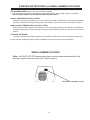
1
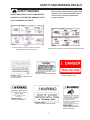
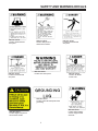
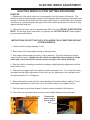
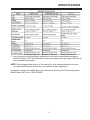
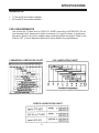
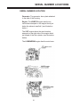
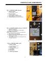
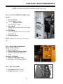
NIGHT-LITE NIGHT-LITE PRO V SERIES VERTICAL TOWER OPERATOR’S MANUAL ALLMAND BROS. INC P.O. BOX 888 HOLDREGE, NE 68949 PHONE: 308/995-4495, 1-800/562-1373 ALLMAND FAX: 308/995-5887 ALLMAND PARTS FAX: 308/995-4883 NIGHT-LITE SERIES 1 INSPECTION CHECK LIST FOR PREPARING THE NIGHT-LITE PROV SERIES FOR DELIVERY OR RENTAL The NIGHT-LITE PRO V SERIES requires service as well as proper operation in order to provide the performance and safety it has been designed for. Never deliver or put a machine into service with known defects or missing instructions or decals. Always instruct the customer in the proper operation and safety procedures as described in the operator’s manual. Always provide the manual with the equipment for proper and safe operation. CHECK LIST: Visually inspect the equipment to ensure that all instructions and decals are in place and legible. Inspect the tower, pulleys, and cables for proper operation. Check the hitch assembly and safety tow chains. Check the outriggers and jacks to make sure they operate properly. Inspect the light assemblies for damage and test for proper operation. Inspect the electrical wiring for signs of damage. Check the ground rod cable and the ground lug. Make sure they are clean, undamaged, and functional. Inspect the tires to ensure good condition and proper inflation. Check oil, fuel, coolant levels, and hydraulic fluid levels. Check to make sure the operator’s manual is with the equipment. Inspect the machine physically for damage and repair if necessary. NOTE: See appropriate section of manual for scheduled maintenance intervals. After completing the inspection check list, operate the tower through a complete operation cycle, following the operating instructions in the operator’s manual. WARNING NEVER ALLOW ANYONE TO OPERATE THE EQUIPMENT WITHOUT PROPER TRAINING! ALWAYS READ THE INSTRUCTIONS FIRST! 2 TABLE OF CONTENTS INSPECTION CHECK LIST.........................................................................................................2 TABLE OF CONTENTS...............................................................................................................3 INTRODUCTION..........................................................................................................................4 SAFETY SYMBOL INFORMATION.............................................................................................4 SAFETY AND WARNING DECALS......................................................................................... 5-6 ELECTRIC WINCH MAST OPERATION................................................................................. 7-9 HYDRAULIC LIFT MAST OPERATION.............................................................................. 10-12 VERTICAL TOWER ADJUSTMENTS.......................................................................................13 MANUAL WINCH MAST OPERATION.....................................................................................14 SPECIFICATIONS................................................................................................................ 15-17 STARTING INSTRUCTIONS............................................................................................... 18-19 SERIAL NUMBER LOCATIONS.......................................................................................... 19-20 CONTROLS AND COMPONENTS...................................................................................... 22-31 ROUTINE MAINTENANCE SCHEDULE...................................................................................32 TROUBLESHOOTING...............................................................................................................33 LIMITED WARRANTY...............................................................................................................34 3 INTRODUCTION This manual provides the information necessary for the safe operation of the Allmand Bros., Inc., NIGHT-LITE PRO V Series light tower. The NIGHT-LITE PRO vertical tower configuration is operated with a single electric winch, a manual winch, or a hydraulic cylinder to raise and lower the tower. Specific operating instructions and specifications are contained in this publication to familiarize the operator and maintenance personnel with the correct and safe procedures necessary to maintain and operate the equipment. Take time to read this book thoroughly. If you are uncertain about any of the information presented in the manual, contact the factory or your dealer for clarification before operation. SAFETY SYMBOLS The purpose of the SAFETY INFORMATION SYMBOL shown below is to attract your special attention to safety related information contained in the text. DANGER WARNING CAUTION FAILURE TO UNDERSTAND AND COMPLY WITH SAFETY RELATED INFORMATIONAL INSTRUCTIONS MAY RESULT IN INJURY TO OPERATOR OR OTHERS. IF YOU DO NOT UNDERSTAND ANY PART OF THIS INFORMATION CONTACT YOUR DEALER FOR CLARIFICATION PRIOR TO OPERATING EQUIPMENT. NOTE The word NOTE is used to bring your attention to supplementary information in relation to various aspects of proper operation and maintenance. NOTE: Keep this manual accessible during operation to provide convenient reference. NOTE: Any reference in this manual to LEFT or RIGHT shall be determined by looking at the trailer from the rear. 4 SAFETY AND WARNING DECALS SAFETY WARNING Refer to these representations of the safety warning decals used on the NIGHT-LITE to insure correct ordering if replacing becomes necessary. ALWAYS REPLACE ANY SAFETY AND INSTRUCTION DECALS THAT BECOME DAMAGED, PAINTED, OR OTHERWISE ILLEGIBLE. 100663 ELECTRIC AND/OR HYDRAULIC WINCH VERTICAL TOWER OPERATING INSTRUCTIONS PART NO. 101404 Location: On left, front and right side of tower section 1. 101208 MANUAL WINCH VERTICAL TOWER OPERATING INSTRUCTIONS PART NO. 090179 Location: Inside left hand door panel. PART NO. 090002 Location: Light bar cover. PART NO. 090160 Location: On pintle hitch. PART NO. 090005 Location: Inside left hand door panel. 5 PART NO. 090161 Location: Right hand side of electric winch cover. SAFETY AND WARNING DECALS PART NO. 090158 Location: Inside left hand door panel. PART NO. 090165 Location: Inside left hand door panel. PART NO. 090166 Location: Side panel on manual winch models. PART NO. 090084 Location: AC control panel. PART NO. 090163 Location: Inside left hand door panel. PART NO. 090162 Location: On ballast access cover. PART NO. 090133 Location: Inside left hand panel below ground lug. PART NO. 090159 Location: Above battery on tower support inside enclosure. PART NO. 090474 Location: Right side panel on manual winch models. 6 ELECTRIC WINCH VERTICAL MAST OPERATION DESCRIPTION OF OPERATION BEFORE RAISING MAST, VISUALLY INSPECT EQUIPMENT FOR DAMAGE OR WEAR. FAMILIARIZE YOURSELF WITH THE LOCATION AND FUNCTION OF ALL OPERATING PARTS BY STUDYING THIS MANUAL. OBSERVE ALL CAUTION DECALS LOCATED ON EQUIPMENT The Allmand NIGHT-LITE V Series tower assembly consists of a seven section telescoping mast which can be extended by operating a single electric winch mounted inside the enclosure. The winch and cable are protected by an integral clutch and a circuit breaker. The clutch is designed to slip when the mast reaches full extension. The circuit breaker TO SET UP TOWER AND RAISE is a safeguard for the clutch. If the clutch is LIGHTS 1. Extend both side outrigger jacks, rear jack misadjusted or inoperative the circuit breaker and tongue jack to stabilize and level the should trip to protect the system from overtrailer. load. The electric winch operates off the 120 NOTE: Jacks should be placed only on volt circuit breaker along with 120 volt recepfirm footing. tacle thus requiring that the 120 volt circuit breaker switch must be on to operate the winch. SAFETY WARNING! The light bar assembly can be rotated into position by releasing the light bar park pin. THE SUPPLEMENTAL GROUND ROD IS To release the park pin, pull the ring and turn A SAFETY DEVICE THAT MAY REDUCE it 90 degrees so that the pin remains in the THE CHANCE OF PERSONAL INJURY FROM STRAY ELECTRICAL CURRENT. retracted position. The light bar is designed Therefore, Allmand recommends using to rotate with enough resistance so that the the ground rod. However, it is the user’s bar will stay in the desired position once the responsibility to determine the requireoperator has directed the lights on the work ments and/or applicability of local, state, zone. if the light bar rotates too easily or does or national electrical code which governs not stay in position, remove the cap plug from the use of the ground rod. the center of the light bar cover and tighten 2. Attach the ground rod to the grounding lug, the nut to achieve the desired resistance and and drive the ground rod fully for adequate SAFETY WARNING! ALWAYS CHECK FOR OVERHEAD OBSTRUCTIONS BEFORE RAISING AND LOWERING MAST. ALLOW 35' CLEARANCE. AVOID ALL OVERHEAD ELECTRICAL WIRES. TO PREVENT INSTABILITY AND HELP ENSURE SAFE OPERATION, ALWAYS PROVIDE PROPER GROUND SUPPORT BEFORE RAISING MAST. electrical ground, as required by local, state, or national code. 3. Start engine and switch electric winch switch to ON. 4. While the tower is still in the down position, position the light bar and lamps so they are aimed at the work zone and tilted at the approximate angle to get maximum coverage once the tower is raised. 5. Stand clear of the tower when raising and lowering the lights. 7 ELECTRIC WINCH VERTICAL MAST OPERATION 6. Operate the electric winch switch to the “up” position to raise tower to the desired height. 7. If lights need to be adjusted for better lighting of the work zone after raising the tower, lower the tower using the “down” switch position and make desired adjustments to the light bar and light fixtures. Raise the tower into position. Repeat this step if necessary. SAFETY WARNING! VISUALLY INSPECT EQUIPMENT FOR DAMAGE BEFORE OPERATING. ALLOW ADEQUATE CLEARANCE AROUND TRAILER FOR TOWER AND INSURE THAT NO PERSONS ARE STANDING IN UNDER THE LIGHTS WHEN LOWERING. TO LOWER TOWER AND LIGHTS 1. Turn off lights. 2. Operate the electric winch switch in the down position to lower the lights to the lowest vertical position. 3. Stop engine. 4. Rotate the light bar into the transport park position (in line with trailer) and engage the park pin by twisting on the park pin ring until the plunger is released and the pin engages the hole in the light bar. 5. Reposition the lamp fixtures for transport by pulling them down into the lowest position and face the fixtures toward the center of the trailer. 6. Remove ground rod from earth. Disconnect wire from ground lug and secure in trailer 7. Raise jacks and rear stand, retract outriggers and secure for towing 8 NOTE: Ensure the detent pins are properly engaged in the outriggers before towing. AUXILIARY HANDLE An emergency crank handle is provided 1. Remove the electrical power from the winch. (Switch Electric Winch Switch to OFF) 2. Insert the handle so that it completely engages with the driveshaft. The handle can be cranked in either direction with the clutch in the engaged position. 3. Always remove the handle from the winch after use. ELECTRIC WINCH ADJUSTMENT ELECTRIC WINCH CLUTCH SETTING PROCEDURE PURPOSE 1. Adjustment of the winch clutch nut is necessary to limit the power of the winch. The clutch nut must be tight enough to prevent clutch slippage when raising the tower and loose enough so that the clutch does slip if the tower should come in contact with some overhead obstruction or be extended past the upper limit switch which would cause the tower to stop against the dead stop bolt. 2. The clutch nut torque value is approximately 28 to 30 in lbs. (DO NOT OVER TIGHTEN) NOTE: The nut may seem loose when it is properly set. DO NOT ADJUST; further tightening may cause cable failure. INSTRUCTIONS FOR SETTING THE CLUTCH UNDER FIELD CONDITIONS WITHOUT A TORQUE WRENCH 1. Loosen clutch nut approximately ½ turn. 2. Stand clear of the tower when raising or lowering tower. 3. Start engine and operate the winch in the up direction. The winch should run but the tower should not move. (At this time the clutch nut should be loose enough to let the clutch slip, if not, back off the clutch nut just enough so the clutch does slip). 4. Start the clutch nut setting procedure by making a slight tightening adjustment until the tower starts to rise. 5. The tower may again stall even while the winch continues to run. If so, lower the tower and make another slight adjustment to the clutch nut, by tightening in the clockwise direction approximately 10 to 20 degrees. 6. Repeat the previous step until the tower reaches full elevation without stalling. Do not make large adjustments to the clutch nut as it would be easy to over tighten the nut. 7. Run the tower up and down at least 5 times to ensure consistent full elevation. 8. The clutch is a serviceable part and may require slight adjustments periodically. View of clutch nut with winch cover removed. Remove this plastic plug to access clutch nut. 9 HYDRAULIC LIFT VERTICAL MAST OPERATION DESCRIPTION OF OPERATION The Allmand NIGHT-LITE V Series hydraulic TO SET UP TOWER AND RAISE lift tower assembly consists of a seven secLIGHTS tion telescoping mast which can be extended 1. Extend both side outrigger jacks, rear jack by operating a single hydraulic cylinder. and tongue jack to stabilize and level the trailer. The light bar assembly can be rotated into position by releasing the light bar park pin. NOTE: Jacks should be placed only on To release the park pin, pull the ring and turn firm footing. it 90 degrees so that the pin remains in the retracted position. The light bar is designed SAFETY WARNING! to rotate with enough resistance so that the bar will stay in the desired position once the operator has directed the lights on the work THE SUPPLEMENTAL GROUND ROD IS zone. if the light bar rotates too easily or does A SAFETY DEVICE THAT MAY REDUCE THE CHANCE OF PERSONAL INJURY not stay in position, remove the cap plug from FROM STRAY ELECTRICAL CURRENT. the center of the light bar cover and tighten Therefore, Allmand recommends using the nut to achieve the desired resistance and the ground rod. However, it is the user’s replace the cap plug. responsibility to determine the requirements and/or applicability of local, state, or national electrical code which governs SAFETY WARNING! the use of the ground rod. 2. Attach the ground rod to the grounding lug, and drive the ground rod fully for adequate electrical ground, as required by local, state, or national code. ALWAYS CHECK FOR OVERHEAD OBSTRUCTIONS BEFORE RAISING AND LOWERING MAST. ALLOW 35' CLEARANCE. AVOID ALL OVERHEAD ELECTRI- 3. Start engine.(NOTE: Tower may be raised and lowered as needed without engine runCAL WIRES. ning.) TO PREVENT INSTABILITY AND HELP 4. While the tower is still in the down position, ENSURE SAFE OPERATION, ALWAYS position the light bar and lamps so they are PROVIDE PROPER GROUND SUPPORT aimed at the work zone and tilted at the apBEFORE RAISING MAST. proximate angle to get maximum coverage once the tower is raised. BEFORE RAISING MAST, VISUALLY INSPECT EQUIPMENT FOR 5. Stand clear of the tower when raising and DAMAGE OR WEAR. FAMILIARIZE lowering the lights. YOURSELF WITH THE LOCATION AND FUNCTION OF ALL OPERATING PARTS BY STUDYING THIS MANUAL. OBSERVE ALL CAUTION DECALS LOCATED ON EQUIPMENT 10 HYDRAULIC LIFT VERTICAL MAST OPERATION 6. Operate the hydraulic lift switch to the “up” position to raise tower to the desired height. 5. Reposition the lamp fixtures for transport by pulling them down into the lowest position and face the fixtures toward the center of the trailer. 7. If lights need to be adjusted for better lighting of the work zone after raising the tower, lower the tower using the “down” switch position and make desired adjustments to the light bar and light fixtures. Raise the tower into position. Repeat this step if necessary. 6. Remove ground rod from earth. Disconnect wire from ground lug and secure in trailer 7. Raise jacks and rear stand, retract outriggers and secure for towing NOTE: Ensure the detent pins are properly engaged in the outriggers before towing. SAFETY WARNING! VISUALLY INSPECT EQUIPMENT FOR DAMAGE BEFORE OPERATING. ALLOW ADEQUATE CLEARANCE AROUND TRAILER FOR TOWER AND INSURE THAT NO PERSONS ARE STANDING IN UNDER THE LIGHTS WHEN LOWERING. TO LOWER TOWER AND LIGHTS 1. Turn off lights. 2. Operate the hydraulic lift switch in the down position to lower the lights to the lowest vertical position. When tower reaches the bottom, run switch for three additional seconds to ensure that the tower is at it’s lowest possible position. 3. Stop engine. 4. Rotate the light bar into the transport park position (in line with trailer) and engage the park pin by twisting on the park pin ring until the plunger is released and the pin engages the hole in the light bar. 11 HYDRAULIC TOWER POWER UNIT POWER UNIT INSTALLATION & START UP PROCEDURE Fill the reservoir with automatic transmission fluid or any clean hydraulic fluid having a viscosity index that is suitable for the climatic conditions in which the unit will be operated. Recommended operating temperature range is +20° F to +180° F. GENERAL START UP INSTRUCTIONS NOTE: The ports are marked on the casting ‘UP’ and ‘DN’. When facing the power unit with the motor up, plug the right hand, or ‘DN’ port. Jog the motor until oil flows from the left hand, or ‘UP’ port. If oil does not flow from the ‘UP’ port, reverse the wire leads on the motor, and repeat. The pump is now primed. Connect the hose (or tubing) to the ‘UP’ port and tighten. Connect the other hose end to the blind end of a fully retracted hydraulic cylinder. With the hose fitting loose, operate the power unit until oil (and no air) bleeds from the fitting. Tighten the fitting. Refill the reservoir. HYDRAULIC FLUID SPEC CHART 12 VERTICAL TOWER ADJUSTMENTS VERTICAL TOWER CORNER GUIDE BLOCK ADJUSTMENT 1. Make sure the corner guide block cover plate is on top of the UHMW (plastic) corner friction block and a 3/8 internal star washer is between the block and the mounting flange of the tower. This washer is necessary to insure a grip between the friction block and the metal flange of the tower. 2. Use 1/8” spacers to center the inside tower in the middle of the outside tower. SEE ILLUSTRATION. 3. Using a .010” shim and .020” shim for spacers, place a .010” shim between the friction block and the inner tower section sides. SEE ILLUSTRATION. 4. Make sure the inner tower is against the 3/8” thick UHMW blocks mounted inside the outer tower and use the .020” shim to set the friction block distance from the inner tower section. SEE ILLUSTRATION. 5. Tighten the ¼-20 nuts. And continue to set all corner friction blocks on all sections using this procedure. 13 MANUAL WINCH VERTICAL MAST OPERATION DESCRIPTION OF OPERATION SAFETY WARNING ALWAYS CHECK FOR OVERHEAD OBSTRUCTIONS BEFORE RAISING AND LOWERING MAST. ALLOW 35' CLEARANCE. AVOID ALL OVERHEAD ELECTRICAL WIRES. TO PREVENT INSTABILITY AND HELP ENSURE SAFE OPERATION, ALWAYS PROVIDE PROPER GROUND SUPPORT BEFORE RAISING MAST. BEFORE RAISING MAST, VISUALLY INSPECT EQUIPMENT FOR DAMAGE OR WEAR. FAMILIARIZE YOURSELF WITH THE LOCATION AND FUNCTION OF ALL OPERATING PARTS BY STUDYING THIS MANUAL. OBSERVE ALL CAUTION DECALS LOCATED ON EQUIPMENT TO ERECT MAST AND RAISE LIGHTS 1. Extend both side outrigger jacks and tongue jack to stabilize and level the trailer. NOTE: Jacks should be placed only on firm footing. SAFETY WARNING THE SUPPLEMENTAL GROUND ROD IS A SAFETY DEVICE THAT MAY REDUCE THE CHANCE OF PERSONAL INJURY FROM STRAY ELECTRICAL CURRENT. Therefore, Allmand recommends using the ground rod. However, it is the user’s responsibility to determine the requirements and/or applicability of local, state, or national electrical code which governs the use of the ground rod. 2. Attach the ground rod to the grounding lug, and drive the ground rod fully for adequate electrical ground, as required by local, state, or national code. 14 3. While the tower is still in the down position, position the light bar and lamps so they are aimed at the work zone and tilted at the approximate angle to get maximum coverage once the tower is raised. 4. Stand clear of the tower when raising and lowering the lights. 5. To turn on lights, flip the breaker switches to the up position. (SEE FIG. 1) 6. Operate the hand crank to raise tower to the desired height. 7. If lights need to be adjusted for better lighting of the work zone after raising the tower, lower the tower and make desired adjustments to the light bar and light fixtures. Raise the tower into position. Repeat this step if necessary. TO LOWER TOWER AND LIGHTS 1. Turn off lights. 2. Operate the hand crank to lower the lights to the lowest vertical position. 3. Stop engine. 4. Rotate the light bar into the transport park position (in line with trailer) and engage the park pin by twisting on the park pin ring until the plunger is released and the pin engages the hole in the light bar. 5. Reposition the lamp fixtures for transport by pulling them down into the lowest position and face the fixtures toward the center of the trailer. 6. Remove ground rod from earth. Disconnect wire from ground lug and secure in trailer 7. Raise jacks and rear stand, retract outriggers and secure for towing NOTE: Ensure the detent pins are properly engaged in the outriggers before towing. NOTE: Visually inspect the flood light mounting yokes for loose hardware. This could prevent a broken fixture during towing. OVERALL DIMENSIONS Weight Length Height lowered Height extended Width (outriggers retracted) Width (outriggers extended) Wheels and tires 1800 LBS 9’ 5” (2.90 m) 7’ (2.13 m) 25' (7.62 m) 4 ‘6” (1.372 m) 7’ 9” (2.36 m) 13" SPECIFICATIONS Low oil pressure and high engine temperature shut-downs are standard equipment. Both The Kubota, CAT, and Lombardini diesel are equipped with glow plug cold start assist as standard equipment. NOTE: See the appropriate section of this manual for cold weather starting instructions or consult the Operators Manual for your particular engine application. Horsepower ratings are established in accordance with Society of Automotive Engineers Small Engine Test Code- J1349 GROSS. 15 SPECIFICATIONS GENERATOR 7.5 kw and 8 kw models available 60 hz and 50 hz models available FUEL REQUIREMENTS Use a clean No. 2 Diesel fuel oil (SAE J313 JUN87) according to ASTM D975. Do not use alternative fuel, because its quality is unknown or it may be inferior in quality,and kerosene, which is very low in cetane rating, adversely effects the engine. Refer to the Kubota, CAT, or Isuzu Operators Manual for more detailed fuel requirements. LOMBARDINI LUBRICATION CHART CAT LUBRICATION CHART KUBOTA LUBRICATION CHART 16 SPECIFICATIONS TRAILER The engine-generator set is housed in a bunded two wheel trailer fabricated from heavy gauge steel. The design enables the trailer to contain the outriggers in a simple, compact position. MAST When the mast is in the operating position it is located in the middle of a three point outrigger system for optimum balance and stability. The mast consists of seven fabricated steel sections that telescope to 25 ft and UHMW plastic guide pads to provide smooth operation and reduced friction. The mast sections are extended with either a manual or electric winch, or hydaulic pump. The electric winch design includes limit switches that turn the winch off when the mast reaches full extension or is fully retracted. STABILIZERS The three point outrigger design consists of two retractable side outriggers and a tongue jack. FLOOD LIGHT ASSEMBLY The flood light assembly consists of four 1250 watt lamp fixtures sealed for all weather use. SHO 1250 fixture - Metal Halide Lamp Lumen rating: 150,000 initial lumens Warm up time: 2-4 minutes Restart time: 10-15 minutes TOWING INSTRUCTIONS Before towing the Night-Lite Pro the trailer should be inspected visually to insure that the following operations have been completed: 1. 2. 3. 4. 5. 6. 7. Hitch is securely attached to the towing vehicle All outriggers and jacks are retracted and secured. Light fixtures are positioned for transport. Doors are closed and secure. Check for adequate tire pressure. Tail lights are connected and operational. Ground rod is removed from ground and secured in trailer. 17 STARTING INSTRUCTIONS BEFORE STARTING: 1. Fill the engine with the right grade of lubricating oil (refer to the proper page of this manual or the Kubota, CAT, or Lombardini diesel operators manual for oil specifications) 2. Ensure there is an adequate supply of diesel fuel. 3. Ensure that the air cleaner is firmly attached and air cleaner seals and hose clamps are properly sealed. Air cleaner element should be checked and replaced if necessary. STARTING ENGINE NOTE: The Kubota diesel engine includes a glow plug cold start system controlled by the yellow preheat button on the control panel. Glow plugs are not needed on a warm engine or if the ambient temperature is above 50 degrees F. The CAT C1.1 and Lombardini LDW 1003 diesel engines include a glow plug cold start system controlled by the ignition switch on the control panel. Glow plugs are not needed on a warm engine or if the ambient temperature is above 50 degrees F. COLD WEATHER STARTING: KUBOTA (for temperatures below 32° F/ 0° C) 1. Turn the on-off switch to the ON position. 2. Press the yellow PREHEAT button for 5 seconds (10 seconds below 23° F maximum 20 seconds continuous). 3. Press the green START button to crank engine until the engine starts. 4. If engine fails to start, it may be necessary to recycle the PREHEAT and Start steps #2 and #3 above COLD WEATHER STARTING: LOMBARDINI LDW 1003 (for temperatures below 32° F/ 0° C) 1. Turn the key switch to the PREHEAT position, hold until the glow plug indicator lamp goes out, then release switch. 2. Turn the key switch to the START position and the engine should start. Release the key immediately when the engine starts. If engine fails to start it may be necessary to cycle the glow plugs again (see chart below) COLD WEATHER STARTING CAT C1.1 (for temperatures below 32° F/ 0° C) 1. If the engine is cold, turn the key switch counterclockwise to the “preheat” position until the glow plug indicator turns red. CAUTION: Never heat glow plugs more than 30 seconds or damage to the glow plugs may occur. 2. Turn the key switch to the “start” position and start the engine immediately once the indicator turns red. NOTE: Do not operate starter for more than 10 seconds without allowing 30 seconds to pass between starting attempts. Possible starter damage could result from excessive heat caused by cranking too long. NOTE: If the engine develops sufficient speed to disengage the starter but does not keep running (a false start), the engine rotation must be allowed to come to a complete stop before attempting to restart the engine. If starter is engaged while the flywheel is rotating, the starter pinion and flywheel ring gear may clash, resulting in damage to the starter or flywheel ring gear. NOTE:If the starter does not turn the engine over, stop cranking immediately. Do not make further attempts to start the engine until the condition is corrected. See your local Kubota, CAT, or Lombardini Engine Service Dealer for trouble analysis. 18 STARTING INSTRUCTIONS and SERIAL NUMBER LOCATIONS FOR A WARM ENGINE (Kubota, CAT, and Lombardini engines) Follow the same procedure as described for cold weather starting, skipping step 1 (step 2 for Kubota). Use of the glow plugs is not recommended when engine is warm. LOW OIL PRESSURE SHUT-OFF SYSTEM Should a low oil pressure condition occur, the oil pressure sending unit breaks the circuit between the battery and the fuel solenoid, allowing the spring load to immediately move the fuel control to the shut-off position. HIGH COOLANT TEMPERATURE SHUT-OFF SYSTEM Should a high coolant temperature condition occur, the temperature sending unit breaks the circuit between the battery and the fuel solenoid, allowing the spring load to immediately move the fuel control to the shut-off position. STOPPING THE ENGINE To stop the engine turn the ignition switch to the off position, this breaks the circuit between the battery and the fuel solenoid, allowing the spring load to immediately move the control to the shut-off position SERIAL NUMBER LOCATION Trailer: All NIGHT-LITE PRO series trailers have a serial number plate attached to the rear tower support below the tower lock. (See illustration) TRAILER SERIAL NUMBER LOCATION 19 SERIAL NUMBER LOCATIONS SERIAL NUMBER LOCATION Generator: The generator has a plate attached to the side of the housing. Engine: The KUBOTA engine has the serial number stamped on the engine block just below the exhaust manifold. (see illustration below ) The CAT engines have the serial number stamped on the right side of the engine block just ahead of the first cylinder. (see illustration below) The LOMBARDINI engine has the serial num- 20 CONTROLS AND COMPONENTS NOTE: PHOTOGRAPHS MAY SHOW NON-STANDARD EQUIPMENT AND OPTIONS 1 2 4 FIG. 1. CONTROL PANEL (Kubota) 1. Breaker Switch Controls lights 1 and 2 2. Breaker Switch Controls lights 3 and 4 3. Electric Winch On/Off Switch 4. Control Panel (see close up below) 3 Fig. 1 Control Panel 1 4 5 FIG. 1a. CONTROL PANEL (Kubota) CLOSE UP 1. Ignition On switch Must be in ON position to start engine 2. Engine Start Button NOTE: Release button as soon as engine fires. 3. Glow Plug Preheat Button 4. Engine Function Indicator Lights come on when there is a fault. 5. Hour Meter shows the total elapsed hours of engine operation 2 3 Fig. 1a Control Panel Close Up 3 FIG. 1b. CONTROL PANEL (CAT) 1. Breaker Switch Controls lights 1 and 2 2. Breaker Switch Controls lights 3 and 4 3. Hour Meter 4. Key Switch 5. Glow Plug Indicator 5 4 1 2 FIG. 1a (CAT) 21 CONTROLS AND COMPONENTS NOTE: PHOTOGRAPHS MAY SHOW NON-STANDARD EQUIPMENT AND OPTIONS FIG. 1c. A.C./D.C.CONTROL PANEL (Lombardini) 5 1 3 1. Breaker Switch Controls lights 1 and 2 2. Breaker Switch Controls lights 3 and 4 3. Hour Meter Shows the total elapsed hours of engine operation. 4. Key Switch Turn key clockwise one click to activate the glow plugs. 5. Glow Plug Lamp NOTE: Release key as soon as the engine fires. 2 4 FIG. 1b (Lombardini) FIG. 2. Winch Switch and Breaker (Electric Winch Model) 1. Breaker (5 Amp) 2. Electric Winch Up/Down Switch Controls raising and lowering of tower (Hydraulic Lift Model) 1. Breaker (5 Amp)(not used) 2. Hydraulic Lift Up/Down Switch 1 2 Fig. 2 Winch Switch and Breaker 2 FIG. 3. BALLAST PANEL 1 1. Transformer (lights 1 thru 4) 2. Capacitors (lights 1 thru 4) 22 FIG. 3 CONTROLS AND COMPONENTS NOTE: PHOTOGRAPHS MAY SHOW NON-STANDARD EQUIPMENT AND OPTIONS 1 FIG. 4. GROUND ROD LOCATION 1. Ground rod should be attached to grounding lug with wire provided and ground rod and then driven fully into the earth for adequate electrical ground, as required by local, state, or national electrical code. FIG. 4 FIG. 5A ENGINE COMPONENT IDENTIFICATION (KUBOTA ) 1. Water temp switch 2. Alternator 3. Starter 4. Air cleaner 5. Oil Pressure Switch 4 1 2 5 3 FIG. 5A 1 2 FIG. 5B. ENGINE COMPONENT IDENTIFICATION (KUBOTA ) 1. Oil fill 2. Glow plugs 3. Fuel solenoid 4. Fuel filter 5. Oil filter 3 5 4 FIG. 5B FIG. 5B FIG. 5C. ENGINE COMPONENT IDENTIFICATION (KUBOTA ) 1. Fuel filter 2. Electric fuel pump 2 23 FIG. 5C 1 CONTROLS AND COMPONENTS NOTE: PHOTOGRAPHS MAY SHOW NON-STANDARD EQUIPMENT AND OPTIONS FIG. 6A ENGINE COMPONENT IDENTIFICATION (KUBOTA) 1. Water temp switch 2. Alternator 3. Starter 4. Air cleaner 4 3 2 1 FIG. 6A 4 FIG. 6B ENGINE COMPONENT IDENTIFICATION (CAT) 1. Water temp switch 2. Alternator 3. Starter 4. Air cleaner 2 1 3 FIG. 6B FIG. 6C ENGINE COMPONENT IDENTIFICATION (LOMBARDINI) 1. Muffler 2. Alternator 3. Oil Filter 4. Air cleaner (not shown) 1 4 2 FIG. 6C 24 3 CONTROLS AND COMPONENTS NOTE: PHOTOGRAPHS MAY SHOW NON-STANDARD EQUIPMENT AND OPTIONS 3 4 FIG. 7A. ENGINE COMPONENT IDENTIFICATION (KUBOTA cont’d) 1. Oil fill 2. Glow plugs 3. Fuel solenoid 4. Electric Fuel Pump 5. Fuel filter 6. Oil filter 2 5 1 6 FIG. 7A FIG. 7A FIG. 7B. ENGINE COMPONENT IDENTIFICATION (CAT cont’d) 1. Oil fill 2. Glow plugs 3. Fuel solenoid 4. Fuel pump 5. Fuel filter 6. Oil filter 1 2 3 5 4 6 FIG. 7B 5 FIG. 7C. ENGINE COMPONENT IDENTIFICATION (LOMBARDINI cont’d) 1. Air Cleaner 2. Starter 3. Fuel pump 4. Fuel filter 5. Cooling Fan 3 1 2 4 FIG. 7C 25 CONTROLS AND COMPONENTS NOTE: PHOTOGRAPHS MAY SHOW NON-STANDARD EQUIPMENT AND OPTIONS FIG. 8a. REMOTE OIL DRAIN LOCATION 1. Remote oil drain valve (Kubota) Open illustrated valve (1) in engine oil pan to drain oil from engine. 1 FIG. 8a FIG. 8b. REMOTE OIL DRAIN LOCATION 1. Remote oil drain valve (CAT) Open illustrated valve (1) in engine oil pan to drain oil from engine. 1 FIG. 8b FIG. 8c. REMOTE OIL DRAIN LOCATION 1. Remote oil drain valve (Lombardini) Open illustrated valve in engine oil pan to drain oil from engine. 1 FIG. 8c FIG. 8d. REMOTE OIL DRAIN LOCATION 1. Remote oil drain (all models) Remove cap to drain engine oil 1 FIG. 8d 26 CONTROLS AND COMPONENTS NOTE: PHOTOGRAPHS MAY SHOW NON-STANDARD EQUIPMENT AND OPTIONS 35 32 2 FIG. 8 REAR PANEL 1. Rear Panel 2. Serial Number Tag 3. Exhaust Outlet 3 33 34 1 FIG. 8 FIG. 9. REAR OUTRIGGERS 1. Jack Handle Crank handle to raise or lower foot of jack to level trailer 2. Jack Pin Pull to allow jack to rotate 3. Outrigger Storage Latch Retains outriggers while in the stored or travel mode 1 3 2 SAFETY WARNING Be sure outrigger jack and outriggers are securely latched before towing. FIG. 9 27 CONTROLS AND COMPONENTS NOTE: PHOTOGRAPHS MAY SHOW NON-STANDARD EQUIPMENT AND OPTIONS FIG. 10 POSITIVE DOOR LATCH 1. Positive door latch Locks door in the open position 1 FIG. 10 1 FIG. 11 MANUAL WINCH 1. Manual Winch—Used to raise and lower vertical mast (shown with safety cover) 2. Manual Winch Handle 2 FIG. 11 1 FIG. 11a MANUAL WINCH 1. Manual Winch—Used to raise and lower vertical mast (shown with safety cover) 2. Manual Winch Handle 2 FIG. 11a 1 FIG. 11b-11c HYDRAULIC TOWER 1. Hydraulic Pump—Used to raise and lower hydraulic lift vertical mast 2. Hydraulic Cylinder—Used to raise and lower hydraulic lift vertical mast FIG. 11b 2 FIG. 11c 28 CONTROLS AND COMPONENTS NOTE: PHOTOGRAPHS MAY SHOW NON-STANDARD EQUIPMENT AND OPTIONS 2 FIG. 12 ELECTRIC WINCH 1. Electric Winch—Used to raise and lower vertical mast (shown without safety cover for clarity) 2. Breaker Switches for outlets 1 FIG. 12 1 FIG. 12a. ELECTRIC WINCH 1. Safety Cover Installed (Left side view) FIG. 12a 1 FIG. 12b. ELECTRIC WINCH 1. Safety Cover Installed (right sideview) FIG. 12b 29 CONTROLS AND COMPONENTS NOTE: PHOTOGRAPHS MAY SHOW NON-STANDARD EQUIPMENT AND OPTIONS 1 FIG. 13. Electric Relay Assembly 1. Relays (Kubota Only) FIG. 13 FIG. 14. Tower Cord Reel Location 1. Cord Reel 1 FIG. 14 4 FIG. 15. LIFTING ATTACHMENT POINTS 1. Forklift Lifting Pockets Used to lift light tower using forklift to ease loading and unloading FIG. 15 30 CONTROLS AND COMPONENTS NOTE: PHOTOGRAPHS MAY SHOW NON-STANDARD EQUIPMENT AND OPTIONS 3 FIG. 16 Vertical Tower 1. Seven Section Vertical Tower 2. Light Mounting Locations --Mount lights here for use during operation 3. Light connector sockets (optional)— attach light leads to light bar at these female receptacles when provided 2 1 FIG. 16 1 FIG. 17 and 17a Light Bar and Mounting Locations 1. Light Bar 2. Light mounting locations —Mount lights here for use during operation 3. Light connector sockets (optional)—attach light leads to light bar at these female receptacles when provided 2 FIG. 17 3 2 1 FIG. 17a 2 FIG. 18 Tower Limit Switch Assembly (Electric Only) 1. Tower Limit Switch 2. Tower Limit Switch Housing 1 31 FIG. 18 ROUTINE MAINTENANCE KUBOTA D905, D1105, CAT C1.1, and LOMBARDINI LDW 1003 INSPECTION AND LUBRICATION SCHEDULE Check condition of the steel cable and make sure it is properly secured. Check hydraulic fluid level. Service intervals shown below have been established for operation under normal conditions. Where equipment is operated under severe conditions (very dusty, extreme heat or cold, etc.) affected items should be serviced more frequently. KUBOTA CAT ONLY LOMBARDINI ONLY 32 TROUBLESHOOTING SAFETY WARNING DANGER! HIGH VOLTAGE! DO NOT ATTEMPT TO TEST AND REPAIR GENERATOR AND BALLAST ELECTRICAL SYSTEMS UNLESS YOU UNDERSTAND AND ARE QUALIFIED TO WORK ON SUCH SYSTEMS. For engine and generator troubleshooting, see engine and generator manuals or contact your dealer. 33 LIMITED WARRANTY Allmand Bros. Inc. PO Box 888 1502 West 4th Ave Holdrege, NE 68949 800-562-1373 / 308-995-4495 Fax 308-995-5887 / www.allmand.com ALLMAND LIGHTING SYSTEMS LIMITED WARRANTY UNITED STATES and U.S. TERRITORIES THIS WARRANTY IS IN LIEU OF ALL OTHER WARRANTIES EXPRESSED OR IMPLIED INCLUDING WARRANTIES OF MERCHANTABILITY OR OF FITNESS FOR PURPOSE AND ANY EXCEPTIONS ARE DESCRIBED IN THE PUBLISHED LIMITED WARRANTY ADDENDUM, AVAILABLE UPON REQUEST. COMPONENTS, SUB-ASSEMBLIES, AND DEVICES MANUFACTURED BY OTHER MANUFAC TURERS ARE NOT COVERED BY THIS WARRANTY. ALL WARRANTY INFORMATION FROM SUCH OTHER MANUFACTURERS IS PROVIDED WITHIN OR ACCOMPANIES THESE GOODS. Subject to the foregoing, the manufacturer, Allmand Bros. Inc., hereby warrants all light towers manufactured by Allmand Bros. Inc. after April 1, 2008 to be free from defects in material and workmanship for a period of (2) years after delivery to the original purchaser. The first year warranty would include parts and labor. The second year warranty would be limited to parts manufactured by Allmand Bros. Inc. and components warranted by the original equipment manufacturer for more than 12 months. Additionally, Allmand Bros. Inc. hereby warrants all replacement parts supplied by Allmand Bros. Inc. to be free from defects in material and workmanship for a period of 90 days after date of invoice. Delivery shall be deemed for the purposes of this warranty to have occurred no later than five days following the date of sale agreement or invoice unless the purchase agreement or invoice specifically states a later delivery date in which case such delivery date shall control. The original purchaser shall be deemed to be a person who places the goods or products in actual use, and any person holding such goods solely for wholesale or retail sale purposes shall not constitute an original purchaser. PROVIDED, any leasing of these goods or other use beyond normal demonstration of same shall be deemed to be in use by an original purchaser and all warranty periods shall commence at the time of such use. During the warranty period any defective goods or parts hereof shall be repaired or replaced at manufacturer’s discretion. In the event it is necessary to return such goods or parts to the factory, all transportation charges shall be prepaid. The manufacturer shall in no event pay mileage expenses, but will warrant outbound ground freight. The manufacturer shall in no event be responsible for down time and or lost revenue. The obligations of the manufacturer is solely to repair or replace defective goods or parts or to refund the cost of the same if it is determined by the manufacturer that repair or replacement will not return the goods to proper working order or utility. THE REMEDIES SET FORTH HEREIN ARE EXCLUSIVE AND MANUFACTURER SHALL NOT BE LIABLE FOR SPECIAL, INDIRECT, OR CONSEQUENTIAL DAMAGES. THE OBLIGATIONS OF THE MANUFACTURER HEREUNDER SHALL IN NO WAY EXCEED THE PRICE OF THE EQUIPMENT OR PART UPON WHICH SUCH LIABILITY IS BASED. The warranty shall not extend to tires, lamps, batteries, or parts that have been altered, changed, damaged, or improperly installed, repaired, operated or maintained. Provided, this exclusion shall not apply to installations, repairs or other work done at the manufacturer’s plant or under direct manufacturer’s supervision. The Operator’s Manual, to the extent covered therein, is deemed to set forth the proper procedures for operation, repair, installation, and maintenance of these goods. No representative, dealer or distributor of the company is authorized to make any changes or exceptions to this warranty unless expressly authorized in writing from the manufacturer. All warranty claims must be filed within thirty (30) days of the failure. 34