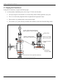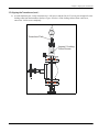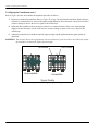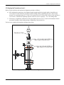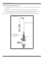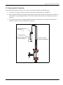
1
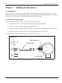
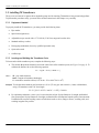
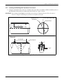
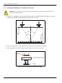
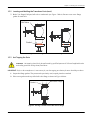
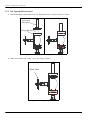
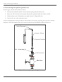
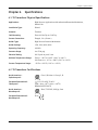
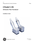
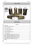
GE
Measurement & Control
Flow
Model T8
Ultrasonic Flow Transducer
Installation Guide
916-075 Rev. D
November 2014
GE
Measurement & Control
Model T8
Ultrasonic Flow Transducer
Installation Guide
916-075 Rev. D
November 2014
www.ge-mcs.com
©2014 General Electric Company. All rights reserved.
Technical content subject to change without notice.
[no content intended for this page]
ii
Preface
Information Paragraphs
Note: These paragraphs provide information that provides a deeper understanding of the situation, but is not
essential to the proper completion of the instructions.
IMPORTANT:
These paragraphs provide information that emphasizes instructions that are essential to proper setup of
the equipment. Failure to follow these instructions carefully may cause unreliable performance.
This symbol indicates a risk of potential minor personal injury and/or severe damage to
the equipment, unless these instructions are followed carefully.
CAUTION!
WARNING! This symbol indicates a risk of potential serious personal injury, unless these instructions
are followed carefully.
Safety Issues
WARNING! It is the responsibility of the user to make sure all local, county, state and national codes,
regulations, rules and laws related to safety and safe operating conditions are met for each
installation.
WARNING! For installations in potentially hazardous areas, be sure to read the Certification and
Safety Statements document at the end of this manual before beginning the installation.
Auxiliary Equipment
Local Safety Standards
The user must make sure that he operates all auxiliary equipment in accordance with local codes, standards,
regulations, or laws applicable to safety.
Working Area
WARNING! Auxiliary equipment may have both manual and automatic modes of operation. As
equipment can move suddenly and without warning, do not enter the work cell of this equipment
during automatic operation, and do not enter the work envelope of this equipment during manual
operation. If you do, serious injury can result.
WARNING! Make sure that power to the auxiliary equipment is turned OFF and locked out before
you perform maintenance procedures on the equipment.
Model T8 Installation Guide
iii
Preface
Qualification of Personnel
Make sure that all personnel have manufacturer-approved training applicable to the auxiliary equipment.
Personal Safety Equipment
Make sure that operators and maintenance personnel have all safety equipment applicable to the auxiliary equipment.
Examples include safety glasses, protective headgear, safety shoes, etc.
Unauthorized Operation
Make sure that unauthorized personnel cannot gain access to the operation of the equipment.
Environmental Compliance
Waste Electrical and Electronic Equipment (WEEE) Directive
GE Measurement & Control Solutions is an active participant in Europe’s Waste Electrical and Electronic Equipment
(WEEE) take-back initiative, directive 2012/19/EU.
The equipment that you bought has required the extraction and use of natural resources for its production. It may
contain hazardous substances that could impact health and the environment.
In order to avoid the dissemination of those substances in our environment and to diminish the pressure on the natural
resources, we encourage you to use the appropriate take-back systems. Those systems will reuse or recycle most of the
materials of your end life equipment in a sound way.
The crossed-out wheeled bin symbol invites you to use those systems.
If you need more information on the collection, reuse and recycling systems, please contact your local or regional
waste administration.
Visit http://www.ge-mcs.com/en/about-us/environmental-health-and-safety/1741-weee-req.html for
take-back instructions and more information about this initiative.
iv
Model T8 Installation Guide
Contents
Chapter 1. Installing the Transducers
1.1
Introduction . . . . . . . . . . . . . . . . . . . . . . . . . . . . . . . . . . . . . . . . . . . . . . . . . . . . . . . . . . . . . . . . . . . . . . . . . . . . . . . . . . . . . . . . . . . . 1
1.2
Transducer Construction. . . . . . . . . . . . . . . . . . . . . . . . . . . . . . . . . . . . . . . . . . . . . . . . . . . . . . . . . . . . . . . . . . . . . . . . . . . . . . . . 1
1.3
Installing T8 Transducers . . . . . . . . . . . . . . . . . . . . . . . . . . . . . . . . . . . . . . . . . . . . . . . . . . . . . . . . . . . . . . . . . . . . . . . . . . . . . . . 2
1.4
1.3.1
Equipment Needed . . . . . . . . . . . . . . . . . . . . . . . . . . . . . . . . . . . . . . . . . . . . . . . . . . . . . . . . . . . . . . . . . . . . . . . . . . . . . 2
1.3.2
Locating and Welding the Transducer Ports . . . . . . . . . . . . . . . . . . . . . . . . . . . . . . . . . . . . . . . . . . . . . . . . . . . . . . 2
1.3.3
Hot Tapping the Ports . . . . . . . . . . . . . . . . . . . . . . . . . . . . . . . . . . . . . . . . . . . . . . . . . . . . . . . . . . . . . . . . . . . . . . . . . . . 5
1.3.4
Positioning the Transducer . . . . . . . . . . . . . . . . . . . . . . . . . . . . . . . . . . . . . . . . . . . . . . . . . . . . . . . . . . . . . . . . . . . . . . 8
1.3.5
Attaching the Hydraulic Cylinder . . . . . . . . . . . . . . . . . . . . . . . . . . . . . . . . . . . . . . . . . . . . . . . . . . . . . . . . . . . . . . .13
1.3.6
Inserting the Transducer . . . . . . . . . . . . . . . . . . . . . . . . . . . . . . . . . . . . . . . . . . . . . . . . . . . . . . . . . . . . . . . . . . . . . . .16
1.3.7
Adjusting the Safety Alignment Collar. . . . . . . . . . . . . . . . . . . . . . . . . . . . . . . . . . . . . . . . . . . . . . . . . . . . . . . . . . .19
1.3.8
Removing the Hydraulic Cylinder . . . . . . . . . . . . . . . . . . . . . . . . . . . . . . . . . . . . . . . . . . . . . . . . . . . . . . . . . . . . . . .21
Resetting or Storing the Hydraulic Cylinder . . . . . . . . . . . . . . . . . . . . . . . . . . . . . . . . . . . . . . . . . . . . . . . . . . . . . . . . . . . . .24
Chapter 2. Aligning the Transducers
2.1
Introduction . . . . . . . . . . . . . . . . . . . . . . . . . . . . . . . . . . . . . . . . . . . . . . . . . . . . . . . . . . . . . . . . . . . . . . . . . . . . . . . . . . . . . . . . . . .27
2.2
Preparing for Transducer Alignment . . . . . . . . . . . . . . . . . . . . . . . . . . . . . . . . . . . . . . . . . . . . . . . . . . . . . . . . . . . . . . . . . . . .27
2.3
Aligning the Transducers . . . . . . . . . . . . . . . . . . . . . . . . . . . . . . . . . . . . . . . . . . . . . . . . . . . . . . . . . . . . . . . . . . . . . . . . . . . . . .28
Chapter 3. Removing the Transducers
3.1
Introduction . . . . . . . . . . . . . . . . . . . . . . . . . . . . . . . . . . . . . . . . . . . . . . . . . . . . . . . . . . . . . . . . . . . . . . . . . . . . . . . . . . . . . . . . . . .33
3.2
Attaching the Hydraulic Cylinder . . . . . . . . . . . . . . . . . . . . . . . . . . . . . . . . . . . . . . . . . . . . . . . . . . . . . . . . . . . . . . . . . . . . . . .33
3.3
Removing the Transducer. . . . . . . . . . . . . . . . . . . . . . . . . . . . . . . . . . . . . . . . . . . . . . . . . . . . . . . . . . . . . . . . . . . . . . . . . . . . . .35
3.4
Disconnecting the Hydraulic Cylinder . . . . . . . . . . . . . . . . . . . . . . . . . . . . . . . . . . . . . . . . . . . . . . . . . . . . . . . . . . . . . . . . . .39
Chapter 4. Specifications
4.1
T8 Transducer Physical Specifications . . . . . . . . . . . . . . . . . . . . . . . . . . . . . . . . . . . . . . . . . . . . . . . . . . . . . . . . . . . . . . . . . .41
4.2
T8 Transducer Certifications . . . . . . . . . . . . . . . . . . . . . . . . . . . . . . . . . . . . . . . . . . . . . . . . . . . . . . . . . . . . . . . . . . . . . . . . . . .41
Model T8 Installation Guide
v
Contents
[no content intended for this page]
vi
Model T8 Installation Guide
Chapter 1. Installing the Transducers
Chapter 1.
Installing the Transducers
1.1 Introduction
The T8 Ultrasonic Flow Transducer is used exclusively with the GE Sensing line of ultrasonic flowmeters. These
transducers measure the flow rate of sonically-conductive gases through pipes having diameters from 4 in. (100 mm) to
36 in. (90 cm). Such measurements are typically independent of the pipe material.
1.2 Transducer Construction
Each T8 transducer assembly (see Figure 1 below) consists of the following:
•
A metallic body with a 1/2” NPT male thread for attaching an electrical junction box
•
A body flange that is welded or machined to the transducer body
•
A transducer with a piezoelectric element mounted on a wedge and wired to a BNC style electrical connector
•
A BNC style electrical connector for use in connecting the transducer to the flowmeter
The T8 is available in various lengths from 12 in. (30 cm) to 72 in. (180 cm).
Transducers
BNC Connector
180
o
Metallic Body
45o
30o
Junction Box
Figure 1: T8 Transducer Assembly
Model T8 Installation Guide
1
Chapter 1. Installing the Transducers
1.3 Installing T8 Transducers
The pressure mechanism is a piston-driven hydraulic pump used for inserting T8 transducers into pressurized pipelines.
To perform this procedure safely, you must follow all the instructions in this chapter very carefully.
1.3.1 Equipment Needed
To properly install the T8 transducers, you must provide the following items:
•
Pipe marker
•
Spiral-wound gaskets (6)
•
Adjustable torque wrench with a 3.75-19 ft-lb (5-20 N-m) range and a socket drive
•
Standard and deep sockets
•
Hot-tapping mechanism (for use by qualified personnel only)
•
Open-end wrench
•
Oscilloscope
1.3.2 Locating and Welding the Transducer Ports
To locate and weld the transducer ports, complete the following steps:
1. The variable H equals the distance between the center lines of the transducer ports (see Figure 2 on page 3). To
calculate the distance H, use the following equation:
H = 2 [ ( ID + 0.325 ) • tan θ + U ]
where:
ID = pipe inside diameter
tan θ = tangent of transducer head angle
U = transducer centerline offset (0.155 for θ = 30° or 0.067 for θ = 45o)
Example: To calculate the transducer port locations on a 30 in. (75 cm) pipe with a 0.40 in. (1 mm) wall thickness,
using a T8 transducer with a 30° head angle:
H = 2 * [(29.2 + 0.325) * tan 30° + 0.155] = 34.40 in.
2. For optimum performance, select a port location that has at least 20 pipe diameters of straight, undisturbed
flow upstream and 10 pipe diameters of straight, undisturbed flow downstream from the point of measurement.
Undisturbed flow means avoiding sources of turbulence such as valves, flanges, elbows; avoiding swirl; and
avoiding irregular flow profiles.
2
Model T8 Installation Guide
Chapter 1. Installing the Transducers
1.3.2 Locating and Welding the Transducer Ports (cont.)
3. Using the calculated H value, mark two crosshairs on the pipe where you intend to weld the transducer ports, so
that the distance between the two marks equals the H value (see Figure 2 below).
IMPORTANT: Port locations should NOT be located directly on the top or bottom of the pipe. Place the ports at
between 15 degrees and 90 degrees from the vertical plane of the pipe.
= 15° min. to 90° max.
θ
Transducer Port
Centerline
Vertical Plane
H ± 0.01“
Example:
H = 34.40“
See Detail A
U
2θ
θ
0.325“
Detail A
Figure 2: Locating the Transducer Ports
Model T8 Installation Guide
3
Chapter 1. Installing the Transducers
1.3.2 Locating and Welding the Transducer Ports (cont.)
WARNING! Only qualified personnel should weld bosses and nozzles, using a suitable ASME IX
qualified welding procedure.
4. Weld the 2 in., schedule 80 nozzles with pipe flanges to the two marked locations on the pipe. Be careful to
maintain perpendicularity and parallelism as shown in Figure 3 below.
2θ
θ
Figure 3: Welding the Nozzles with Flanges to the Pipe
5. Inspect the flange gaskets. They must not be previously used, warped, pitted or scratched.
6. Place one gasket on the top of each pipe nozzle flange, as shown in Figure 4 below.
Gasket
Pipe Nozzle Flange
Pipe
Figure 4: Placing a Gasket on a Pipe Nozzle Flange
4
Model T8 Installation Guide
Chapter 1. Installing the Transducers
1.3.2 Locating and Welding the Transducer Ports (cont.)
7. Bolt a 2 in. flanged, full-port, ball valve to each nozzle (see Figure 5 below). Be sure to use a new flange
gasket for each valve.
Ball Valve
Gasket
Figure 5: Mounting a Ball Valve onto the Flange
1.3.3 Hot Tapping the Ports
WARNING! Hot tapping should only be performed by qualified personnel. Follow all applicable code
and safety practices during these procedures.
IMPORTANT: Refer to the manufacturer’s instructions for your hot-tapping mechanism for more detailed procedures.
1. Inspect the flange gaskets. They must not be previously used, warped, pitted or scratched.
2. Place a new gasket on the top of the ball valve flange, as shown in Figure 6 below.
Gasket
Ball Valve Flange
Figure 6: Placing a Gasket on the Ball Valve Flange
Model T8 Installation Guide
5
Chapter 1. Installing the Transducers
1.3.3 Hot Tapping the Ports (cont.)
3. Bolt the hot-tapping mechanism to the 2 in. flanged ball valve, as shown in Figure 7 below.
Hot-Tapping
Mechanism
Flanged Ball Valve
Figure 7: Securing the Hot-Tapping Mechanism
4. Make sure the ball valve is fully “open” (see Figure 8 below).
Open Valve
Figure 8: Checking the Open Valve
6
Model T8 Installation Guide
Chapter 1. Installing the Transducers
1.3.3 Hot Tapping the Ports (cont.)
5. Drill a 1.75 in. diameter hole through the pipe wall, as shown in Figure 9 below.
Valve
Open
Recommended
D = 1.75“ to 1.93”
D = 1.68“ min. to 2.067” max.
Figure 9: Drilling a Hole Through the Pipe Wall
6. Retract the drill bit of the hot-tapping mechanism and “close” the ball valve (see Figure 10 below).
Close Valve
Figure 10: Closing the Ball Valve
Model T8 Installation Guide
7
Chapter 1. Installing the Transducers
1.3.3 Hot Tapping the Ports (cont.)
7. Unbolt the hot-tapping mechanism from the ball valve and remove the mechanism from the port (see Figure 11
below).
Remove
Hot-Tapping
Mechanism
Flanged Ball Valve
Valve
Closed
Figure 11: Removing the Mechanism from the Port
8. Repeat steps 1 through 7 to hot tap the other port.
1.3.4 Positioning the Transducer
Complete the steps in this section to position the T8 transducer in the hot-tapped port.
Note: Keep the cover for the safety collar loosely around the transducer to allow for proper alignment.
1. Measure the transducer length (“DD”) from the center of the transducer head to the end of the BNC connector.
DD = Center of the Transducer Head
to the End of the BNC Connector.
DD
Figure 12: Measuring the Transducer Length
8
Model T8 Installation Guide
Chapter 1. Installing the Transducers
1.3.4 Positioning the Transducer (cont.)
2. Make sure the transducer head is fully retracted into the Low Pressure Assembly (LPA). If the transducer is not
fully retracted, loosen all the screws of the locking collar and manually retract the transducer into the LPA (see
Figure 13 below).
Locking Collar Detail
1/4-20 x 1.375 LG SOC HD SCREW (2)
10-32 x 3/4 SOC HD SCREW (4)
Fully Retracted
Transducer Head
Figure 13: Transducer Head Fully Retracted
3. Rotate the transducer barrel until the transducer face points in the general direction of the other port. Then,
tighten the locking collar screws with a torque wrench to fasten the transducer in place. Use the maximum
torque shown in Figure 14 below, but do not overtighten the screws. Alternate the tightening sequence of the
six screws to properly “seat” the locking collar.
IMPORTANT: The long flat or the flat marked “F” is in line with the transducer face (see Figure 14 below). To aid the
installation, make a mark on the flange indicating the direction of the transducer face.
Locking Collar Detail
1/4-20 x 1.375 LG SOC HD SCREW (2)
Max Torque 5 ft-lb (6.8 N-m)
Transducer Head
10-32 X 3/4 SOC HD SCREW (4)
max Torque 3.75 ft-lb (5 N-m)
Long Flat or Flat Marked “F”
Use the transducer barrel to rotate
the transducer head in the general
direction of the other port.
This Mark Indicates
the Transducer Face Direction
Figure 14: Rotating the Transducer Barrel
Model T8 Installation Guide
9
Chapter 1. Installing the Transducers
1.3.4 Positioning the Transducer (cont.)
4. Inspect the flange gaskets. They must not be previously used, warped, pitted or scratched.
5. Place a new gasket on the top of the ball valve flange (see Figure 15 below).
Ball Valve Flange
New Gasket
Valve
Closed
Figure 15: Placing a New Gasket on the Flange
6. Bolt the LPA mechanism to the 2 in. flanged ball valve, as shown in Figure 16 below.
Valve
Closed
Valve
Closed
Figure 16: Bolting the LPA Mechanism to the Ball Valve
10
Model T8 Installation Guide
Chapter 1. Installing the Transducers
1.3.4 Positioning the Transducer (cont.)
7. Measure the “A” dimension, which is the distance from the outside surface of the pipe wall to the end of the
BNC connector on the transducer (see Figure 17 below). Then, calculate the insertion distance (“I”) by using
the following equation:
I = A + W – ( C + DD )
where:
A = distance from the pipe wall to the end of the BNC connector on the transducer
W = pipe wall thickness
C = 0.325 in. (a constant)
DD = distance from the center of the transducer head to the end of the BNC connector, as measured in step 1.
A
Valve
Closed
Pipe Wall Thickness
Figure 17: Measuring the “A” Dimension
Model T8 Installation Guide
11
Chapter 1. Installing the Transducers
1.3.4 Positioning the Transducer (cont.)
8. Mark the insertion distance on the shaft of the transducer, using one layer of colored electrical tape around the
circumference so that the ends overlap (see Figure 18 below). Alternatively, apply any mark that is waterproof
and easily identifiable.
Insertion Depth Marker
Use this Edge
(bottom edge of tape)
Insertion Distance
Valve
Closed
Insertion Distance
I = A + W - C - DD
Figure 18: Marking the Insertion Distance
9. Repeat steps 1 through 8 to position the other transducer in the other port.
12
Model T8 Installation Guide
Chapter 1. Installing the Transducers
1.3.5 Attaching the Hydraulic Cylinder
The next step in the transducer installation process is to attach the hydraulic cylinder to one of the transducer ports.
1. Install the connector protector on the 1/2” NPT thread of the transducer shaft until it is finger-tight (see
Figure 19 below).
Connector
Protector
Connector
Protector
Transducer Shaft
Valve
Closed
Valve
Closed
Figure 19: Installing the Connector Protector
Model T8 Installation Guide
13
Chapter 1. Installing the Transducers
1.3.5 Attaching the Hydraulic Cylinder (cont.)
2. Refer to Figure 20 below and attach the hydraulic cylinder to the four studs of the LPA with four 3/8-16 hex
nuts. Tighten the nuts to a maximum torque of 19 ft-lb (25 N-m).
IMPORTANT: If the piston of the hydraulic cylinder touches the connector protector before the hydraulic cylinder can
seat properly onto the studs, remove the hydraulic cylinder from the LPA. Connect the hydraulic pump to
the hydraulic cylinder, and refer to “Resetting or Storing the Hydraulic Cylinder” on page 24 to move
the piston to the appropriate position.
Piston
Hydraulic Cylinder
3/8 - 16 Hex Nuts (4)
Max. Torque
19 ft-lb (25 N-m)
LPA
Valve
Closed
Valve
Closed
Figure 20: Attaching the Hydraulic Cylinder
14
Model T8 Installation Guide
Chapter 1. Installing the Transducers
1.3.5 Attaching the Hydraulic Cylinder (cont.)
3. Refer to Figure 21 below and attach the hose of the hydraulic pump to the hydraulic cylinder at the pipe
coupler.
Note: The 2 in. ball valve should be closed and the locking collar should be tightly secured to the transducer shaft.
Pipe Coupler
Hose
Hydraulic Cylinder
Hydraulic Pump
Locking Collar
Tightly Secured
Valve
Closed
Figure 21: Attaching the Hydraulic Pump
Model T8 Installation Guide
15
Chapter 1. Installing the Transducers
1.3.6 Inserting the Transducer
After attaching the hydraulic cylinder, you are now ready to insert the T8 transducer.
1. To prepare for pumping, rotate the side knob of the hydraulic pump clockwise to tighten it (see Figure 22
below).
2. Slowly pump the handle of the pump until you feel resistance, then stop pumping. The resistance indicates that
the piston is applying pressure to the transducer.
Piston Touching
Connector Protector
Tighten Side Knob
Clockwise
Pump Handle
Stop pumping when
you feel resistance.
Valve
Closed
Figure 22: Tightening the Hydraulic Pump Side Knob
16
Model T8 Installation Guide
Chapter 1. Installing the Transducers
1.3.6 Inserting the Transducer (cont.)
3. There are four 10-32 x 3/4 socket head screws and two 1/4-20 x 1 3/8 socket head screws on the locking collar
(see Figure 23 below). Evenly loosen these screws. just enough so that the transducer can move freely.
Locking Collar Detail
1/4-20 x 1.375 LG SOC HD SCREW (2)
10-32 X 3/4 SOC HD SCREW (4)
LPA Purge
Valve Closed
Valve
Closed
Figure 23: Loosening the Socket Head Screws
4. Before opening the ball valve do the following:
•
Make sure the LPA purge valve (see Figure 23 above) is in the “Closed” position.
•
Verify that the hydraulics are engaged and the transducer shaft has pressure applied (there should be
resistance when the pump handle is pumped).
WARNING! Make sure you perform the above checks before opening the ball valve, otherwise
personal injury or damage to the equipment may occur.
Model T8 Installation Guide
17
Chapter 1. Installing the Transducers
1.3.6 Inserting the Transducer (cont.)
5. Slowly open the 2 in. ball valve and check for gas leaks:
•
If you discover any leaks, close the ball valve and fix the leaks.
•
If you do not detect any leaks, proceed to the next step.
6. See Figure 24 below and slowly pump the hydraulic pump handle until the transducer moves to the pre-marked
insertion depth, as indicated by the edge of the electrical tape touching the edge of the locking collar. You will
feel resistance on the hydraulic pump handle as you insert the transducer against the line pressure.
Insert to Here
10-32 X 3/4 SOC HD SCREW (4)
Max Torque 3.75 ft-lb (5 N-m)
1/4-20 x 1.375 LG SOC HD SCREW (2)
Max Torque 5 ft-lb (6.8 N-m)
Valve
Open
Figure 24: Pumping the Hydraulic Pump Handle
7. Tighten the locking collar screws with a torque wrench to fasten the transducer in place. Use the maximum
torque listed in Figure 24 above, but do not overtighten the screws.
Note: Alternate the tightening sequence of the six screws to properly “seat” the locking collar.
18
Model T8 Installation Guide
Chapter 1. Installing the Transducers
1.3.7 Adjusting the Safety Alignment Collar
The next step in the transducer installation procedure is to adjust the safety alignment collar.
1. Locate the safety alignment collar that was shipped with the T8 transducer.
2. Use an Allen wrench to remove the two socket head cap screws and the set screw from the safety alignment
collar (see Figure 25 below).
Set Screw
Safety Alignment
Collar
Socket Head Cap Screw
Figure 25: Preparing the Safety Alignment Collar for Installation
3. Using the socket head cap screws, loosely attach the safety alignment collar to the barrel of the transducer (see
Figure 26 below).
Safety
Alignment
Collar
Transducer Small
Diameter Slot
Cover for Safety Collar
1/4-20 X 5/8 Socket
Head Cap Screws
Figure 26: Attaching the Collar to the Transducer Barrel
Model T8 Installation Guide
19
Chapter 1. Installing the Transducers
1.3.7 Adjusting the Safety Alignment Collar (cont.)
4. Slide the safety alignment collar into the safety collar cover and position both collars so that they are touching
the safety plate (see Figure 27 below).
Note: If necessary, adjust the height of both screws on the safety collar cover to allow the safety alignment collar to
fit into it.
1/4-28 x 5/8
Socket Screws
Safety
Alignment
Collar
Safety Plate
Safety Collar Cover
1/4-20 x 5/8 Socket
Head Cap Screws
Figure 27: Positioning the Safety Alignment Collar
5. Secure the safety alignment collar by tightening the two 1/4-28 x 5/8 socket head screws with an Allen wrench.
Then, install the set screw in the threaded hole of the safety adjustment collar (see Figure 28 below).
1/4-28 x 5/8 Socket Head Screws
Max Torque 9.17 ft-lb (12.4 N-m)
1/4-20 x 3/8 Set Screws
Max Torque 5 ft-lb (6.8 N-m)
Figure 28: Securing the Safety Alignment Collar
20
Model T8 Installation Guide
Chapter 1. Installing the Transducers
1.3.8 Removing the Hydraulic Cylinder
The final step in the T8 transducer installation process is the removal of the hydraulic cylinder from the port.
1. Verify that the screws on the locking and safety alignment collars are tightened to the appropriate torque. Then,
very slowly turn the side knob of the hydraulic pump counterclockwise to release the pressure of the hydraulic
cylinder on the transducer shaft (see Figure 29 below).
Slowly turn side knob
counterclockwise
to release pressure.
Verify screws are torqued.
Figure 29: Releasing the Hydraulic Cylinder Pressure
Model T8 Installation Guide
21
Chapter 1. Installing the Transducers
1.3.8 Removing the Hydraulic Cylinder (cont.)
2. See Figure 30 below and remove the hydraulic cylinder by unscrewing the four 3/8-16 stainless steel hex nuts.
Quick Disconnect
Unscrew hex
nuts and remove
hydraulic cylinder.
Remove connector
protector.
Figure 30: Removing the Hydraulic Cylinder
3. Unscrew and remove the connector protector (see Figure 30 above).
Note: Disconnecting the hydraulic pump at the quick-disconnect pipe coupler simplifies the hydraulic cylinder
removal.
22
Model T8 Installation Guide
Chapter 1. Installing the Transducers
1.3.8 Removing the Hydraulic Cylinder (cont.)
4. Attach the pipe adapter to the 1/2” NPT thread of the transducer, and then attach the junction box to the pipe
adapter. Use a wrench on the flats of the transducer body to prevent transducer rotation when installing the
junction box (see Figure 31 below).
Junction Box
Pipe Adapter
Coaxial Cable
Flats for Wrench
Figure 31: Installing the Junction Box and Transducer Cable
5. Connect a coaxial cable to the transducer to complete the installation for this port (see Figure 31 above).
Note: Use a junction box with a straight-through hub when submersible/waterproof cable is connected to the
transducer.
6. Connect the transducer to your flowmeter electronics console, as described in the flowmeter User’s Manual.
Repeat the procedures described in this chapter to install the second T8 transducer. After both transducers have been
installed, proceed to the next section.
Model T8 Installation Guide
23
Chapter 1. Installing the Transducers
1.4 Resetting or Storing the Hydraulic Cylinder
To prepare the hydraulic cylinder for its next use or for storage, you must retract the piston.
1. Remove the safety pin and attach the guide for the push rod to the hydraulic cylinder with four 3/8-16 hex nuts
(see Figure 32 below). Save the safety pin for future use.
Remove Safety Pin
Push Rod Guide
Attach with 3/8 - 16 Hex Nuts (4)
Figure 32: Retracting the Piston
2. If it was previously removed, re-attach the hydraulic pump to the hydraulic cylinder at the pipe coupler (see
Figure 33 below).
Hydraulic Pump
Pipe Coupler
Hydraulic Cylinder
Figure 33: Reattaching the Hydraulic Pump
24
Model T8 Installation Guide
Chapter 1. Installing the Transducers
1.4 Resetting or Storing the Hydraulic Cylinder (cont.)
3. Turn the side knob of the hydraulic pump counterclockwise to release the oil pressure (see Figure 34 below).
Turn side knob
counterclockwise.
Figure 34: Releasing the Oil Pressure
4. Hold the cylinder with one hand, and push the rod with the other hand until the piston bottoms out inside the
cylinder (see Figure 35 below).
Hold here with other hand.
Push Rod
Hold here with one hand.
Figure 35: Pushing the Rod into the Cylinder
5. Do one of the following:
•
If you are ready to insert a transducer into a port, proceed to the appropriate section of this chapter.
•
If you have already installed both transducers, proceed to step 6 on the next page.
Model T8 Installation Guide
25
Chapter 1. Installing the Transducers
1.4 Resetting or Storing the Hydraulic Cylinder (cont.)
6. Position the 0.28 in. diameter hole of the push rod to align with the 0.28 in. diameter hole of the push rod
guide. Then, push the safety pin through the holes to secure the cylinder, push rod and push rod guide assembly
(see Figure 36 below).
Align holes here.
Safety Pin
Push or Pull
Safety Pin
Push Rod
Push Rod Guide
Hydaulic Cylinder
Figure 36: Aligning the Push Rod and Guide
After both transducers are installed and the hydraulic cylinder has been stored, proceed to the next chapter to align your
T8 transducers.
26
Model T8 Installation Guide
Chapter 2. Aligning the Transducers
Chapter 2.
Aligning the Transducers
2.1 Introduction
After you finish installing the T8 transducers, as described in the previous chapter, you must fine tune the transducer
alignment using the procedures in this chapter.
IMPORTANT: Alignment is not necessary for the T8 transducer with a 180° head. Skip this chapter.
2.2 Preparing for Transducer Alignment
To prepare for alignment of the T8 transducers, complete the following steps:
1. Make sure the flowmeter electronics console is powered ON and that the transducers are properly connected to
the flowmeter.
2. From the Diagnostic menu on the flowmeter, display the transducer signal strength on the electronics console.
If necessary, refer to your flowmeter Service Manual for instructions.
3. As described in your flowmeter Service Manual, connect an oscilloscope to the transducer terminals.
4. Find the signal strength, quality and amplitude limits in the troubleshooting/diagnostics section of the
flowmeter Service Manual. You will need to know these limits to complete the alignment procedure.
Model T8 Installation Guide
27
Chapter 2. Aligning the Transducers
2.3 Aligning the Transducers
To align the T8 transducers, complete the following steps:
1. At each transducer installation point, refer to Figure 37 below and verify that:
•
The safety alignment collar and the cover for the safety collar are firmly against the safety plate
•
The screws on the safety alignment collar are tightened to the appropriate torque
•
Each transducer is positioned at the correct insertion depth
•
The transducer face points directly toward the other transducer (check the flat and the flange mark)
1/4-28 x 5/8 Socket Head Screws
Max Torque 9.17 ft-lb (12.4 N-m)
Safety Plate
1/4-20 x 3/8 Set Screws
Max Torque 5 ft-lb (6.8 N-m)
Collars are “butting”
against safety plate.
Correct Insertion
Depth
Transducer
Direction Mark
This transducer faces opposite transducer.
Figure 37: Aligning the Transducers
28
Model T8 Installation Guide
Chapter 2. Aligning the Transducers
2.3 Aligning the Transducers (cont.)
2. At each transducer port, evenly loosen the two 1/4-20 screws and the four 10-32 screws just enough to free the
locking collar from the transducer shaft (see Figure 38 below). If the locking collar will not come loose,
remove the 1/4-20 screws completely.
Transducer Flats
Loosen 6 Locking
Collar Screws
Figure 38: Freeing the Locking Collar
Model T8 Installation Guide
29
Chapter 2. Aligning the Transducers
2.3 Aligning the Transducers (cont.)
Refer to Figure 39 below and continue the alignment procedure as follows:
3. Position a wrench on the transducer flats (see Figure 38 on page 29) and rotate the transducer about one degree
clockwise or counterclockwise. Observe the signal strength displayed on the flowmeter console for at least two
or three readings or observe the receive signal on the oscilloscope.
4. Rotate the other transducer about one degree clockwise or counterclockwise. Observe the signal strength
displayed on the flowmeter console for at least two or three readings or observe the receive signal on the
oscilloscope.
5. Alternately rotate the two transducers until the signal strength, signal amplitude and the signal quality are
optimized.
IMPORTANT: You can only observe the signal quality with an oscilloscope. If you do not have an oscilloscope, adjust
the transducers to obtain the highest signal strength.
1st Packet
Unacceptable
2nd Packet
Acceptable
Signal Quality
Figure 39: Observing the Signal Strength
30
Model T8 Installation Guide
Chapter 2. Aligning the Transducers
2.3 Aligning the Transducers (cont.)
Refer to Figure 40 below and continue the alignment procedure as follows:
6. After adjusting the transducers for the highest signal strength and the best signal quality, reinstall the two
1/4-20 screws at each transducer port and secure the locking collar by tightening the screws with a torque
wrench. Use a maximum torque of 3.75 ft-lb (5 N-m) on the four 10-32 screws and 5 ft-lb (6.8 N-m) on the two
1/4-20 screws. Alternate the tightening sequence of the six screws to properly “seat” the locking collar.
7. If necessary, re-tighten the junction box to the pipe adapter. Be sure to use a wrench on the transducer flats to
prevent the transducer from rotating during re-tightening of the junction box.
You have now completed the transducer alignment procedure.
Transducer Flats
1/4-20 x 1.375 LG SOC HD SCREW (2)
Max Torque 5 ft-lb (6.8 N-m)
10-32 X 3/4 SOC HD SCREW (4)
Max Torque 3.75 ft-lb (5 N-m)
Figure 40: Completing the Transducer Alignment Procedure
Model T8 Installation Guide
31
Chapter 2. Aligning the Transducers
[no content intended for this page]
32
Model T8 Installation Guide
Chapter 3. Removing the Transducers
Chapter 3.
Removing the Transducers
3.1 Introduction
To safely remove the T8 transducers from the process line, you must follow the instructions in this chapter very
carefully.
WARNING! Make sure the flowmeter power is disconnected before performing the procedures in this
chapter.
3.2 Attaching the Hydraulic Cylinder
Begin the transducer removal process by referring to Figure 41 below and completing the following steps:
1. Disconnect the coaxial cable from the transducer.
2. Use a wrench on the flats of the pipe adapter to prevent it from rotating, and remove the junction box from the
pipe adapter.
Disconnect
Coaxial Cable
Pipe Adapter Flats
Transducer Flats
Figure 41: Preparing to Remove a Transducer
Model T8 Installation Guide
33
Chapter 3. Removing the Transducers
3.2 Attaching the Hydraulic Cylinder (cont.)
3. Use a wrench on the flats of the transducer body to prevent the transducer from rotating, and disconnect the
pipe adapter.
4. Place the connector protector onto the 1/2” NPT thread of the transducer shaft and finger-tighten it.
5. Attach the hydraulic cylinder to the four studs on the LPA, using four 3/8-16 stainless steel nuts (see Figure 42
below). Tighten the four 3/8-16 stainless steel hex nuts to a maximum torque of 19 ft-lb (25 N-m).
Note: Disconnecting the hydraulic pump at the “quick disconnect” will simplify attaching the hydraulic cylinder.
Quick Disconnect
Hydraulic Cylinder
3/8 - 16 Hex Nuts (4)
Max. Torque
19 ft-lb (25 N-m)
LPA
Figure 42: Attaching the Hydraulic Cylinder
34
Model T8 Installation Guide
Chapter 3. Removing the Transducers
3.3 Removing the Transducer
After attaching the hydraulic cylinder, refer to Figure 43 below and complete the following steps:
1. To prepare for pumping, rotate the side knob of the hydraulic pump clockwise to tighten it.
2. Slowly pump the handle of the pump to bring the piston into contact with the connector protector. When you
feel resistance, stop pumping the handle. The resistance indicates that the piston is touching the connector
protector.
3. Verify that the hydraulics are engaged and that the transducer shaft has pressure applied, as indicated by a
feeling of resistance when the pump handle is pumped).
Tighten side knob
clockwise.
Pump Handle
Stop pumping when
you feel resistance.
Piston touching
connector protector.
Figure 43: Pumping to Move the Piston
Model T8 Installation Guide
35
Chapter 3. Removing the Transducers
3.3 Removing the Transducer (cont.)
Refer to Figure 44 below and continue as follows:
4. Use an Allen wrench to remove the set screw from the safety alignment collar.
5. Evenly loosen the two 1/4-28 x 5/8 socket head cap screws with an Allen wrench just enough to slide the safety
alignment collar out of the cover.
6. Remove the alignment collar from the transducer by removing the two 1/4-28 x 5/8 socket head cap screws.
Note: Alternatively, you may mark the spot with a waterproof pen.
1/4-28 x 5/8 Socket Head
Cap Screws
Remove screws
and then remove
collar.
Remove
1/4-20 x 3/8 Set Screw
Figure 44: Removing the Alignment Collar
36
Model T8 Installation Guide
Chapter 3. Removing the Transducers
3.3 Removing the Transducer (cont.)
7. Refer to Figure 45 below and check the condition of the insertion depth marker. If it was erased or otherwise
damaged, replace the marker with one layer of colored electrical tape around the transducer circumference
until the ends overlap. Place the edge of the tape against the edge of the locking collar.
Insertion Depth
Marker
The edge of the tape
and the locking collar
meet here.
Figure 45: Checking the Insertion Depth Marker
8. Make sure the piston of the hydraulic cylinder is still applying positive pressure to the connector protector (see
Figure 46 below). Then, evenly loosen the screws in the locking collar just enough to free the collar from the
transducer shaft.
Make sure pressure is still applied.
Evenly loosen locking
collar screws (6).
Figure 46: Loosening Locking Collar Screws
Model T8 Installation Guide
37
Chapter 3. Removing the Transducers
3.3 Removing the Transducer (cont.)
Refer to Figure 47 below and continue as follows:
9. After the locking collar is loose, very slowly turn the side knob of the hydraulic pump counterclockwise to
release the pressure and allow the transducer to slowly slide out of the flange.
10. After the transducer head is completely retracted inside the LPA, turn the 2 in. flanged ball valve to its closed
position.
Proceed to the next section to complete the removal procedure.
Loosen side knob
counterclockwise.
When transducer is
retracted, close ball valve.
Figure 47: Releasing the Pressure
38
Model T8 Installation Guide
Chapter 3. Removing the Transducers
3.4 Disconnecting the Hydraulic Cylinder
To remove the hydraulic cylinder, refer to Figure 48 below and complete the following steps:
1. Tighten the locking collar screws with a torque wrench to secure the transducer in place. Use the maximum
torque listed in Figure 48 above, but do not overtighten the screws.
IMPORTANT: Alternate the tightening sequence of the six screws to properly “seat” the locking collar.
2. Open the purge valve to vent and release the gas pressure trapped inside the LPA.
Open Purge
Valve
10-32 X 3/4 SOC HD SCREW (4)
Max Torque 3.75 ft-lb (5 N-m)
1/4-20 x 1.375 LG SOC HD SCREW (2)
Max Torque 5 ft-lb (6.8 N-m)
Figure 48: Preparing to Remove the Hydraulic Cylinder
Model T8 Installation Guide
39
Chapter 3. Removing the Transducers
3.4 Disconnecting the Hydraulic Cylinder (cont.)
Refer to Figure 49 below and continue as follows:
1. Disconnect the hydraulic cylinder from the hydraulic pump at the quick disconnect.
2. Remove the four 3/8-16 hex nuts to detach the hydraulic cylinder from the four studs of the LPA.
3. Unbolt and remove the LPA/transducer assembly from the 2” flanged ball valve.
4. Unscrew and remove the connector protector.
You have completed the removal procedure for this transducer. If necessary, repeat the process to remove the other
transducer. After both transducers have been removed, properly store the hydraulic cylinder for future use.
Quick Disconnect
Hydraulic Cylinder
Connector Protector
3/8 - 16 Hex Nuts (4)
LPA/Transducer
Ball Valve
Figure 49: Removing the Hydraulic Cylinder
40
Model T8 Installation Guide
Chapter 4. Specifications
Chapter 4.
Specifications
4.1 T8 Transducer Physical Specifications
Applications:
High-Pressure Applications with anInsertion/Retraction Mechanism,
Natural Gas
Installation Type:
Wetted
Material:
Titanium
Field Mounting:
Flowcell, Hot Tap or Cold Tap
Process Connection:
Flanged, 2 in. (50 mm )
Holder Type:
High-Pressure Insertion Mechanism
Holder Ratings:
150#, 300#, 600#, 900#
Operating Frequency:
100 kHz
Pressure Range:
0 to 2700 psig
Electrical Rating:
200 V peak-to-peak, 5 mA
Ambient Temperature Range:
Europe: –40°F to +140°F (–40°C to +60°C)
North America: –4°F to +140°F (–20°C to +60°C)
Process Temperature Range:
–58°F to +302°F (–50°C to +150°C)
4.2 T8 Transducer Certifications
North American Explosion proof:
European/International Flameproof:
Class I, Division 1, Group C, D
II 2 G Ex d IIC T6 60°C
Tamb –40 to +60oF (–40 to +140oC)
KEMA02ATEX2283X
North American Weatherproof:
European/International Weatherproof:
Model T8 Installation Guide
IP66, TYPE 4X, 200Vpp, 5mA
IP 66
41
Chapter 4. Specifications
[no content intended for this page]
42
Model T8 Installation Guide
Warranty
Warranty
Each instrument manufactured by GE Sensing is warranted to be free from defects in material and workmanship.
Liability under this warranty is limited to restoring the instrument to normal operation or replacing the instrument, at
the sole discretion of GE Sensing. Fuses and batteries are specifically excluded from any liability. This warranty is
effective from the date of delivery to the original purchaser. If GE Sensing determines that the equipment was
defective, the warranty period is:
•
one year from delivery for electronic or mechanical failures
•
one year from delivery for sensor shelf life
If GE Sensing determines that the equipment was damaged by misuse, improper installation, the use of unauthorized
replacement parts, or operating conditions outside the guidelines specified by GE Sensing, the repairs are not covered
under this warranty.
The warranties set forth herein are exclusive and are in lieu of all other warranties whether
statutory, express or implied (including warranties or merchantability and fitness for a
particular purpose, and warranties arising from course of dealing or usage or trade).
Return Policy
If a GE Sensing instrument malfunctions within the warranty period, the following procedure must be completed:
1. Notify GE Sensing, giving full details of the problem, and provide the model number and serial number of the
instrument. If the nature of the problem indicates the need for factory service, GE Sensing will issue a
RETURN AUTHORIZATION NUMBER (RAN), and shipping instructions for the return of the instrument to
a service center will be provided.
2. If GE Sensing instructs you to send your instrument to a service center, it must be shipped prepaid to the
authorized repair station indicated in the shipping instructions.
3. Upon receipt, GE Sensing will evaluate the instrument to determine the cause of the malfunction.
Then, one of the following courses of action will then be taken:
•
If the damage is covered under the terms of the warranty, the instrument will be repaired at no cost to the owner
and returned.
•
If GE Sensing determines that the damage is not covered under the terms of the warranty, or if the warranty has
expired, an estimate for the cost of the repairs at standard rates will be provided. Upon receipt of the owner’s
approval to proceed, the instrument will be repaired and returned.
Model T8 Installation Guide
43
Warranty
[no content intended for this page]
44
Model T8 Installation Guide
GE
Sensing
DECLARATION
OF
CONFORMITY
DOC-0028, Rev. G
GE Sensing
1100 Technology Park Drive
Billerica, MA 01821
USA
We,
declare under our sole responsibility that the
Models T3, T5, T8, T11, T14 and T17 Wetted Ultrasonic Flow Transducers
Series BWT1 / F...PA / XAMP... Ultrasonic Flowmeter Transducer Assembly
to which this declaration relates, are in conformity with the following standards:
• EN 60079-0: 2012
• EN 60079-1: 2007
• II 2 G Ex d IIC T6...615°C Gb T3: KEMA06ATEX0052, T5: KEMA01ATEX2045X,
T8: KEMA02ATEX2283X,
T11: KEMA02ATEX2252, T14: KEMA04ATEX2054X, T17: KEMA01ATEX2045X
Series BWT1 / F...PA / XAMP...: KEMA01ATEX2051X; IEC Ex KEM09.0010X
(DEKRA, Ultrechtseweg, 310 Arnhem, The Netherlands - NoBo 0344)
• EN 61326-1: 2006, Class A, Table 2, Industrial Locations
• EN 61326-2-3: 2006
• EN 61010-1: 2012, Overvoltage Category II
Other standards used:
• EN 50014: 1997 + A1, A2
• EN 50018: 2000
following the provisions of the 2004/108/EC EMC and 94/9/EC ATEX Directives.
Where products were initially assessed for compliance with the Essential Health and Safety Requirements of the
ATEX Directive 94/9/EC using earlier harmonized standards, a subsequent review has determined that “technical
knowledge” is unaffected by the current harmonized standards listed above.
The units listed above and any ancillary equipment supplied with them do not bear CE marking for the Pressure
Equipment Directive. They are supplied in accordance with Article 3, Section 3 (sound engineering practices and
codes of good workmanship) of the Pressure Equipment Directive 97/23/EC for DN<25.
Billerica - January 2014
Issued
Mr. Gary Kozinski
Certification & Standards, Lead Engineer
[no content intended for this page]
Customer Support Centers
U.S.A.
The Boston Center
1100 Technology Park Drive
Billerica, MA 01821
U.S.A.
Tel: 800 833 9438 (toll-free)
978 437 1000
E-mail: [email protected]
Ireland
Sensing House
Shannon Free Zone East
Shannon, County Clare
Ireland
Tel: +353 (0)61 470200
E-mail: [email protected]
An ISO 9001:2008 Certified Company
www.ge-mcs.com/en/about_us/quality.html
www.ge-mcs.com
©2014 General Electric Company. All rights reserved.
Technical content subject to change without notice.
916-075 Rev. D