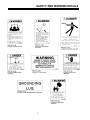
1
NIGHT-LITE 6330 AND 8330 OPERATOR’S MANUAL ALLMAND BROS. INC P.O. BOX 888 HOLDREGE, NE 68949 PHONE: 308/995-4495, 1-800/562-1373 ALLMAND FAX: 308/995-5887 ALLMAND PARTS FAX: 308/995-4883 NIGHT- LITE SERIES For Parts and Updates visit Allmand on the Web at www.allmand.com 1 INSPECTION CHECK LIST FOR PREPARING THE NIGHT-LITE 6330 FOR DELIVERY OR RENTAL The NIGHT-LITE 6330 requires service as well as proper operation in order to provide the performance and safety it has been designed for. Never deliver or put a machine into service with known defects or missing instructions or decals. Always instruct the customer in the proper operation and safety procedures as described in the operator’s manual. Always provide the manual with the equipment for proper and safe operation. CHECK LIST: Visually inspect the equipment to ensure that all instructions and decals are in place and legible. Inspect the tower latch and knob assembly which locks the tower in the vertical position for proper operation Check the hitch assembly and safety tow chains Check the outriggers and jacks to make sure they operate properly Inspect the light assemblies for damage and test for proper operation Inspect the electrical wiring for signs of damage Check the ground rod cable and the ground lug. Make sure they are clean, undamaged, and functional. Inspect the tires to ensure good condition and proper inflation Check oil, fuel, coolant levels, and hydraulic fluid levels. Check to make sure the operator’s manual is with the equipment. Inspect the machine physically for damage and repair if necessary. NOTE: See appropriate section of manual for scheduled maintenance intervals. After completing the inspection check list, operate the tower through a complete operation cycle, following the operating instructions in the operator’s manual. ! WARNING NEVER ALLOW ANYONE TO OPERATE THE EQUIPMENT WITHOUT PROPER TRAINING! ALWAYS READ THE INSTRUCTIONS FIRST! 2 TABLE OF CONTENTS INSPECTION CHECK LIST ..................................................................................................... 2 TABLE OF CONTENTS ........................................................................................................... 3 INTRODUCTION ...................................................................................................................... 4 SAFETY SYMBOL INFORMATION .......................................................................................... 4 SAFETY AND WARNING DECALS ...................................................................................... 5-7 MANUAL WINCH MAST OPERATION .................................................................................. 8-9 ELECTRIC WINCH MAST OPERATION ............................................................................10-11 SPECIFICATIONS ............................................................................................................. 12-13 SERIAL NUMBER LOCATION ............................................................................................... 14 SPECIFICATIONS ............................................................................................................. 15-17 CONTROLS AND COMPONENTS ................................................................................... 18-25 ROUTINE MAINTENANCE SCHEDULE ............................................................................... 26 LISTER-PETTER LPW-3 ROUTINE MAINTENANCE SCHEDULE ............................................................................... 27 KUBOTA D905 D1105 AND PERKINS 103-10 TROUBLESHOOTING ........................................................................................................... 28 ASSEMBLY PARTS AND ACCESSORIES ........................................................................... 29 3 INTRODUCTION This manual provides the information necessary for the safe operation of the Allmand Bros., Inc., NIGHT-LITE 6330 light tower. The NIGHT-LITE 6330 standard tower configuration is operated by a two manual crank winches or single electric winch used to erect, extend, and lower the tower. Specific operating instructions and specifications are contained in this publication to familiarize the operator and maintenance personnel with the correct and safe procedures necessary to maintain and operate the equipment. Take time to read this book thoroughly. If you are uncertain about any of the information presented in the manual, contact the factory or your dealer for clarification before operation. SAFETY SYMBOLS The purpose of the SAFETY INFORMATION SYMBOL shown below is to attract your special attention to safety related information contained in the text. ! DANGER ! WARNING ! CAUTION FAILURE TO UNDERSTAND AND COMPLY WITH SAFETY RELATED INFORMATIONAL INSTRUCTIONS MAY RESULT IN INJURY TO OPERATOR OR OTHERS. IF YOU DO NOT UNDERSTAND ANY PART OF THIS INFORMATION CONTACT YOUR DEALER FOR CLARIFICATION PRIOR TO OPERATING EQUIPMENT. NOTE The word NOTE is used to bring your attention to supplementary information in relation to various aspects of proper operation and maintenance. NOTE: Keep this manual accessible during operation to provide convenient reference. NOTE: Any reference in this manual to LEFT or RIGHT shall be determined by looking at the trailer from the rear. 4 SAFETY AND WARNING DECALS ! SAFETY WARNING Refer to these representations of the safety warning decals used on the MAXI-LITE to insure correct ordering if replacing becomes necessary. ALWAYS REPLACE ANY SAFETY AND INSTRUCTION DECALS THAT BECOME DAMAGED, PAINTED, OR OTHERWISE ILLEGIBLE. PART NO. D-151 Location: Inside left hand door panel of Lister Petter engine units. PART NO. D-249 Location: Inside left hand door panel of Kubota engine units. 5 PART NO. D-264 Location: Inside left hand door panel. SAFETY AND WARNING DECALS 6 SAFETY AND WARNING DECALS 7 MANUAL WINCH MAST OPERATION DESCRIPTION OF OPERATION The Allmand NIGHT-LITE 6330 tower assembly consists of a three section telescoping mast which can be raised and extended by operating two hand crank winches. One winch, mounted with the handle extending through the side of the trailer frame, raises and lowers the mast from the horizontal towing position, the vertical position, and back. The second winch mounted on the tower extends the telescopic sections. The three section mast assembly can be rotated from the ground by loosening a knob and rotating the entire assembly 360° to aim the lights as necessary. ! SAFETY WARNING ALWAYS CHECK FOR OVERHEAD OBSTRUCTIONS BEFORE RAISING AND LOWERING MAST. ALLOW 35' CLEARANCE. AVOID ALL OVERHEAD ELECTRICAL WIRES. TO PREVENT INSTABILITY AND HELP ENSURE SAFE OPERATION, ALWAYS PROVIDE PROPER GROUND SUPPORT BEFORE RAISING MAST. BEFORE RAISING MAST, VISUALLY INSPECT EQUIPMENT FOR DAMAGE OR WEAR. FAMILIARIZE YOURSELF WITH THE LOCATION AND FUNCTION OF ALL OPERATING PARTS BY STUDYING THIS MANUAL. OBSERVE ALL CAUTION DECALS LOCATED ON EQUIPMENT NOTE: The latch locks the mast in the vertical position and disengages the sections allowing the tower assembly to be rotated to position the lights. 8 TO ERECT MAST AND RAISE LIGHTS 1. Extend both side outrigger jacks, rear jack and tongue jack to stabilize and level the trailer. NOTE: Jacks should be placed only on firm footing. ! SAFETY WARNING WHEN EXTENDING REAR JACK, WATCH TO ENSURE YOU ARE CLEAR OF THE OVERHANGING ENDS OF THE MAST BEFORE YOU STAND UP. THE SUPPLEMENTAL GROUND ROD IS A SAFETY DEVICE THAT MAY REDUCE THE CHANCE OF PERSONAL INJURY FROM STRAY ELECTRICAL CURRENT. Therefore, Allmand recommends using the ground rod. However, it is the user’s responsibility to determine the requirements and/or applicability of local, state, or national electrical code which governs the use of the ground rod. 2. Attach the ground rod to the grounding lug, and drive the ground rod fully for adequate electrical ground, as required by local, state, or national code. 3. Release the pin that secures the mast to the rear mast support. 4. Operate the hand crank on the side of the trailer to raise the mast from horizontal to vertical. 5. Turn black knob counterclockwise and engage latch in strike plate. Retighten black knob. 6. Operate the hand crank winch on the tower clockwise to raise the lights vertically. 7. To rotate the lights, release the black knob and turn the tower assembly with the handles provided. 8. To turn on lights, flip the breaker switches to the up position. (SEE FIG. 1) MANUAL WINCH MAST OPERATION ! SAFETY WARNING 6. Operate the hand crank on the side of the trailer counterclockwise to fold the mast down into the towing position. IF THE TOWER CANNOT BE ROTATED AFTER LOOSENING THE BLACK KNOB, CHECK TO ASSURE THE LOWER LATCH IS ENGAGED IN THE STRIKE PLATE. THIS DOUBLE LATCH FEATURE PREVENTS THE TOWER FROM BEING ROTATED IF THE LATCH IS NOT ENGAGED. ! NOTE: Sufficient load (75 lb. min ) must be applied to the cable to overcome internal resistance and operate the brake properly. Insufficient load will not turn the reel thus continual turning without sufficient load will remove the winch handle from the shaft. SAFETY WARNING 7. Secure light cords into hook on the rear tower support for towing. 8. Secure pin locking mast to rear tower support. 9. Remove ground rod from earth. Disconnect wire from ground lug and secure in trailer 10. Raise jacks and rear stand, retract outriggers and secure for towing VISUALLY INSPECT EQUIPMENT FOR DAMAGE BEFORE OPERATING. ALLOW ADEQUATE CLEARANCE AROUND TRAILER FOR TOWER AND INSURE THAT NO PERSONS ARE STANDING IN FRONT OF OR BEHIND UNIT WHEN LOWERING. TO LOWER MAST AND LIGHTS NOTE: Ensure the detent pins are properly engaged in the outriggers before towing. 1. 2. Turn off lights. Release black knob and rotate tower until winch handle points to the front of the trailer and retighten knob. 3. Operate hand crank winch on tower counterclockwise to lower the lights to the lowest vertical position 4. Operate hand crank winch on side of trailer clockwise to take up any cable slack. 5. Turn the black knob counterclockwise and lift to release the latch from the strike plate. Retighten the knob with the latch disengaged from the strike plate. NOTE: Visually inspect the flood light mounting yokes for loose hardware. This could prevent a broken fixture during towing. 9 STRONG ARM ELECTRIC WINCH MAST OPERATION DESCRIPTION OF OPERATION The Allmand NIGHT-LITE 6330 tower assembly consists of a three section telescoping mast which can be raised and extended by operating a single electric winch mounted inside the enclosure. A single three position toggle switch mounted on the control panel is used to raise and lower the mast. The winch and cable are protected by an integral clutch and a circuit breaker. The clutch is designed to slip when the mast reaches full extension. The circuit breaker is a safeguard for the clutch. If the clutch is misadjusted or inoperative the circuit breaker should trip to protect the system from overload. The electric winch operates off the 120 volt circuit breaker along with 120 volt receptacle thus requiring that the 120 volt circuit breaker switch must be on to operate the winch. The three section mast assembly can be rotated from the ground by loosening a knob and rotating the entire assembly 360° to aim the lights as necessary. ! SAFETY WARNING! ALWAYS CHECK FOR OVERHEAD OBSTRUCTIONS BEFORE RAISING AND LOWERING MAST. ALLOW 35' CLEARANCE. AVOID ALL OVERHEAD ELECTRICAL WIRES. TO PREVENT INSTABILITY AND HELP ENSURE SAFE OPERATION, ALWAYS PROVIDE PROPER GROUND SUPPORT BEFORE RAISING MAST. NOTE: The latch locks the mast in the vertical position and disengages the sections allowing the tower assembly to be rotated to position the lights 10 BEFORE RAISING MAST, VISUALLY INSPECT EQUIPMENT FOR DAMAGE OR WEAR. FAMILIARIZE YOURSELF WITH THE LOCATION AND FUNCTION OF ALL OPERATING PARTS BY STUDYING THIS MANUAL. OBSERVE ALL CAUTION DECALS LOCATED ON EQUIPMENT TO ERECT MAST AND RAISE LIGHTS 1. Extend both side outrigger jacks, rear jack and tongue jack to stabilize and level the trailer. NOTE: Jacks should be placed only on firm footing. ! SAFETY WARNING WHEN EXTENDING REAR JACK, WATCH TO ENSURE YOU ARE CLEAR OF THE OVERHANGING ENDS OF THE MAST BEFORE YOU STAND UP. THE SUPPLEMENTAL GROUND ROD IS A SAFETY DEVICE THAT MAY REDUCE THE CHANCE OF PERSONAL INJURY FROM STRAY ELECTRICAL CURRENT. Therefore, Allmand recommends using the ground rod. However, it is the user’s responsibility to determine the requirements and/or applicability of local, state, or national electrical code which governs the use of the ground rod. 2. Attach the ground rod to the grounding lug, and drive the ground rod fully for adequate electrical ground, as required by local, state, or national code. 3. Release the pin that secures the mast to the rear mast support. 4. Operate the hand crank on the side of the trailer to raise the mast from horizontal to vertical. 5. Turn black knob counterclockwise and engage latch in strike plate. Retighten black knob. 6. Operate the hand crank winch on the tower clockwise to raise the lights vertically. 7. To rotate the lights, release the black knob and turn the tower assembly with the handles provided. 8. To turn on lights, flip the breaker switches to the up position. (SEE FIG. 1) STRONG ARM ELECTRIC WINCH MAST OPERATION ! SAFETY WARNING IF THE TOWER CANNOT BE ROTATED AFTER LOOSENING THE BLACK KNOB, CHECK TO ASSURE THE LOWER LATCH IS ENGAGED IN THE STRIKE PLATE. THIS DOUBLE LATCH FEATURE PREVENTS THE TOWER FROM BEING ROTATED IF THE LATCH IS NOT ENGAGED. ! SAFETY WARNING VISUALLY INSPECT EQUIPMENT FOR DAMAGE BEFORE OPERATING. ALLOW ADEQUATE CLEARANCE AROUND TRAILER FOR TOWER AND INSURE THAT NO PERSONS ARE STANDING IN FRONT OF OR BEHIND UNIT WHEN LOWERING. TO LOWER MAST AND LIGHTS 6. Operate the hand crank on the side of the trailer counterclockwise to fold the mast down into the towing position. NOTE: Sufficient load (75 lb. min ) must be applied to the cable to overcome internal resistance and operate the brake properly. Insufficient load will not turn the reel thus continual turning without sufficient load will remove the winch handle from the shaft. 7. Secure light cords into hook on the rear tower support for towing. 8. Secure pin locking mast to rear tower support. 9. Remove ground rod from earth. Disconnect wire from ground lug and secure in trailer 10. Raise jacks and rear stand, retract outriggers and secure for towing NOTE: Ensure the detent pins are properly engaged in the outriggers before towing. 1. 2. Turn off lights. Release black knob and rotate tower until winch handle points to the front of the trailer and retighten knob. 3. Operate hand crank winch on tower counterclockwise to lower the lights to the lowest vertical position 4. Operate hand crank winch on side of trailer clockwise to take up any cable slack. 5. Turn the black knob counterclockwise and lift to release the latch from the strike plate. Retighten the knob with the latch disengaged from the strike plate. NOTE: Visually inspect the flood light mounting yokes for loose hardware. This could prevent a broken fixture during towing. 11 SPECIFICATIONS NOTE. In testing the Lister-Petter engine at the factory, the manufacturer uses an oil for moderate and low temperatures. This oil is specially formulated to assist in the break in period, and we would like it to be left in the engine for the first 100 hours. Additional information on fuel and lubrication specifications is found in the Lister Petter Industrial Engine Operators Handbook. See the KUBOTA 905 EBG1 or 1105 EBG1 Engine Operators Handbook or the PERKINS 103-10 Engine Operators Handbook for information on oil and fuel requirements. TOWING INSTRUCTIONS Before towing the NIGHT-LITE 6330 the trailer should be inspected visually to insure that the following operations have been completed. 1. 2. 3. 4. 5. 6. 7. 8. Hitch is securely attached to towing vehicle (safety chain secure). All outriggers and jacks are retracted and secured. Tower is lowered and the rear tower support pin is in place. Light fixtures are positioned for transport. Doors are closed and secure. Check for adequate tire pressure. Taillights are connected and operating (if equipped). Ground rod is removed from ground and secured in the trailer GROUND ROD INSTRUCTIONS 1. 2. 3. 4. 5. Remove ground rod stowed aside the left door (attached to the lower frame) Unroll the electrical wire lead from the ground rod. Attach the ground rod lead to the grounding lug located near the ballast compartment. Drive the ground rod a minimum of 2 1/2 FT into the earth for adequate electrical grounding. If this is not possible consult your local qualified electrician. AFTER SHUTDOWN OF ENGINE: Remove the ground rod from the earth, remove lead from the trailer ground lug and store ground rod inside left door. 12 SPECIFICATIONS BEFORE STARTING 1. Fill the engine with the right grade of lubricating oil (see pg. 19) and to correct level (check dipstick). 2. Ensure there is an adequate supply of fuel. 3. Ensure that the air cleaner is firmly attached, the air canister seals and the hose clamps are properly sealed. Air cleaner element should be checked and replaced if necessary. 4. Install the ground rod. DESCRIPTION OF OPERATION By depressing the start assist switch, the fuel solenoid is energized. The solenoid plunger is drawn into the coil and activates the fue! control linkage to RUN position. When the engine starts, adequate engine oil pressure at the oil pressure switch will maintain the solenoid in the energized position. The start assist switch can be released as soon as the engine starts. A 10A inline fuse protects the solenoid from electrical damage. LOW OIL PRESSURE SHUTOFF SYSTEM Should a low oil pressure condition occur (less than 5 PSI), the pressure sending unit breaks the circuit between the battery and the fuel solenoid, allowing the spring load to immediately move the fuel control to the shutoff position. HIGH COOLANT TEMPERATURE SHUTOFF SYSTEM NOTE: At temperatures below 30 F. depress the preheat switch for approximately one minute before going on to step 3. 3. Depress start switch until the engine fires. Release start assist switch and start switch as soon as the engine starts. NOTE: To prevent equipment damage, do not hold start switch in for more thon 10 seconds Allow cool down time between cranking intervals. STOPPING THE LISTER PETTER ENGINE 1. Turn ON/OFF toggle switch to the down (OFF) position. STARTING THE KUBOTA AND PERKINS ENGINES NOTE: The Kubota and the Perkins engines includes a glow plug cold start system controlled by the ignition switch on the control panel. Glow plugs are not needed on a warm engine or if the ambient temperature is above 50 F. Do not use starting fluid or ether. 1. Turn the ignition switch to the PREHEAT position and hold until the glow plug lamp goes out. 2. Turn the ignition switch to the Start position until the engine starts. Release key as soon as the engine starts. 3. If engine fails to start it may be necessary to cycle the glow plugs again. Should a high coolant temperature condition occur, the temperature sending unit breaks the circuit between the battery and the fuel solenoid, allowing the spring NOTE: To prevent equipment damage, DO NOT load to immediately move the fuel control to the shutoff hold ignition switch for more than 10 seconds position. in the start position. If the engine does not start in 10 seconds, wait 30 seconds and try the start sequence again. Do not run the cell motor for STARTING/STOPPING INSTRUCTIONS more than 20 seconds continuously. Limit STARTING THE LISTER PETTER ENGINE engine cranking to 3 attempts with a 2 minute cooi-down between each. After 3 attempts allow NOTE: LPW-3 Lister includes a glow plug and cold to cool to ambient temperature. start system controlled by the start assist switch on the control panel. This switch also activates the fuel STOPPING THE KUBOTA AND PERKINS ENsolenoid for quick starts. Use the switch routinely GINES during engine starts. 1. Turn ON/OFF toggle switch to the up (ON) position. 2. Depress preheat, start-assist switch engaging the fuel solenoid and powering the glow plug. Hold in until step 3 (next column) has been completed 1. Turn the ignition switch to the OFF position. This breaks the circuit between the battery and the fuel solenoid, allowing the spring load to immediately move the fuel control to the shutoff position. 2. Disconnect the ground rod. 13 MODEL AND SERIAL NUMBERING SYSTEM SERIAL NUMBER LOCATION Trailer: All NIGHT-LITE 6330 models have a serial number plate located just below the rear tower support on the rear panel. Generator: Plate attached to the side of the generator housing. Engine: Plate attached to the engine. LPW – 3 Top of intake manifold. KUBOTA D905-BG and D1105-BG Left side, between manifold and starter. ISUZU 3LB1 and PERKINS 103-10: Upper right front corner behind injector pump DESCRIPTION OF MODELS AND OPTIONS The NIGHT-LITE 6330 light tower uses four 1000 Watt Metal Halide lamps with the exclusive Allmand SHO lighting system to produce a total of 334,204 lumens (83,551 lumens per fixture). Optional reflective visors and 6light units are available. The lights are mounted on either a manual winch or electric winch tower. The manual tower is operated by two hand crank winches. One winch, mounted on the trailer frame, erects the mast from the horizontal towing position to vertical. The second winch, mounted on the tower, extends the mast vertically to the desired height. The second tower is operated by a 120V electric winch located inside the trailer housing. The electric winch erects the mast from horizontal to vertical and by releasing a lock handle extends the mast vertically to the desired height. The tower power cords are available as either straight cord or a cord reel. Inside fixture storage is offered for the 4-light option. The heavy duty trailer shell has 12 gauge doors and roof panels. The shell houses the 15” wheels and tires inside the side panels. The front panels are rust proof ABS plastic. The NIGHT-LITE 6330 light tower is powered by either a Lister Petter LPW-3 16.5 hp water cooled engine, one of two Kubota water cooled engines, 10.5 hp or 13.6 hp., or an Isuzu water cooled 16 hp diesel engine. Each engine mounts to either the 6KW or 8KW generator. The trailer houses a 50 gallon poly fuel tank and an optional sound attenuation package. 14 SPECIFICATIONS ELECTRICAL Hard wired electrical circuits Easily serviceable componentized ballast assemblies. Ground rod. Hour meter. Voltmeter (optional) External 120V and 240V outlets (optional). FLOOD LIGHT ASSEMBLY Four or six 1000 watt lamp fixtures sealed for all weather use. Lamps can be either the SHO 1000 fixture, 1250 watt fixture or PowerLite fixture. SHO 1000 FIXTURE - BT-37 lamp, Metal Halide, Laboratory rated life is 10,000 hours. Lumen rating: 110,000 Warm-up time: 2-4 minutes Restart time: 10-15 minutes POWERLITE FIXTURE = BT=56 1000 watt Multi-Vapor lamp, Metal Halide, Laboratory rated life is 12,000 hours. Lumen rating: 110,000 Warm-up time: 2-4 minutes Restart time: 10-15 minutes POWERLITE FIXTURE - E-25 1000 watt High Pressure Sodium lamp (often referred to as H.P.S), Laboratory rated life is 24,000 hours. Lumen rating: 140,000 Warm-up time: 4-6 minutes Restart time: 1 minute NOTE: A trailer equipped with Metal Halide lights and a trailer equipped with High Pressure Sodium lights use different ballasts and starters. Therefore, it is not advisable to interchange bulb types. MAST Three-section steel tube mast, which extends to 30 feet. The mast is extended with either two manual winches or one Dutton-Lainson electric winch. The assembly includes self-lubricating nylon guide rollers and 360° rotating light bar. TRAILER The complete generator is housed in a lockable enclosure with the frame fabricated from heavy gauge steel mounted on a twowheel, leaf spring axle. The design enables the trailer to contain the outriggers in a simple compact position. When the mast is in the operating position it is located in the middle of a four point outrigger system for optimum balance and stability. This system was engineered to allow the light plant to remain operational in sustained winds of 65 MPH with the mast extended to full height and the outriggers in position. The design includes an adjustable-height reversible hitch, which includes a 2” ball and pintle hook hitch. STABILIZERS Four (4) point outrigger design. with tower center mounted between two (2) retractable side outriggers, tongue and rear jack. 15 SPECIFICATIONS NIGHT-LITE 6330 DIMENSIONS Height lowered: Height extended: Length: Width: Outrigger width: Trailer: Wheels & tires: 6’6" (1.98 m) 30’ (9.14 m) 14’9” (4.49 m) 6’4”(1.92 m) 11’6”(3.5 m) Structural steel frame Leaf spring axle 15" FUEL AND LUBRICATING OIL The temperatures mentioned in the table are the ambient temperatures at the time the engine is started. 16 However, if the running ambient temperatures are much higher than the starting temperatures, a compromise must be made and a higher viscosity oil used (provided starting is satisfactory). Multigrade oils overcome the problem, provided they have a suitable specification. DOMESTIC SHIPPING WEIGHT Fixtures: Trailer with mast: Total weight: 15 Ibs. ea. = 60 Ibs. 1,990 Ibs. (902.7 kg) 2,050 Ibs. (929.9 kg) SPECIFICATIONS LPW-3 ENGINE KUBOTA D 1105-EBG1 ENGINE LISTER LPW-3 Alpha Series, direct injection 3 Cylinder Kubota D1105-EBG1, indirect injection 3 Cylinder Displacement: Displacement: Bore: Stroke: Power output: Power output derating: 85.13 cu. (1396.13 cc) 3.38 in. (8.6 cm) 3.15 in.(8.0 cm) 16.5 BHP continuous 3.5% for every 1000 ft 68.53 cu. (1.1 cm) Bore: 3.07 in. (78 mm) Stroke: 3.09 in. (78.4 mm) Power output: 13.6 @ 1800 rpm Power output derating: 3.0% for every1000 ft. altitude (305 m) above sea level Air inlet temp: 2% per lO°F (5.6C) above 85° F(29.4C) Fuel: Diesel Fuel consumption: 1.25 ga (4.7L/hr) at less than 75%load Oil sump capacity (excluding filter): 4.0 US qt. (3.8L) Starting: 12 volt electric Low oil pressure shutdown, high engine temp. shutdown, and glow plug cold start assist are standard. KUBOTA D905-EBG1 ENGINE Kubota D905-EBG1, indirect injection 3 Cylinder Displacement: 54.80 cu. in.(898 cm) Bore: 2.83 in. (72 mm) Stroke: 2.90 in. (73.6 mm) Power output: 10.5 BHP@ 1800 rpm Power output derating: 3.0% for every1000 ft. altitude (305 m) above sea level Ambient temp: 1% per 10° F (5.6°C) above 77°F (25°C) Fuel: Diesel Fuel consumption: 0.63 US gal (2.39 L/hr) Starting: Glow plugs needed below 45' F. 12V electric Oil sump capacity (excluding filter) 5.40 US qt. (5.14L) Low oil pressure shutdown, high engine temp. shutdown, and glow plug cold start assist are standard. altitude (305 m) above 360 ft. Ambient temp: 1% per 10°F (5.6°C) above 77°F (25°C) Fuel: Diesel Fuel consumption: Starting: .63 gal (2.39 L)/hr Glow plugs needed below 45 F. 12\/ electric Oil sump capacity (excluding filter): 5.4 US qt. (5.14 L) Low oil pressure shutdown, high engine temp. shutdown, and glow plug cold start assist are standard. PERKINS 103.10 ENGINE Perkins 103.10, Indirect injection 3 Cylinder Displacement: Bore: Stroke: Power output: Power output derating: 58.3 cu. in. (954 cc) . 75 mm 72 mm 10.7 BHP@ 1800 RPM 3.5% for every 1000 ft altitude (305 m) above sea level Air Inlet Temp: 1% per 10°F (5.6C) above 77° F (25°C) Fuel: Diesel Oil sump capacity: Fill to correct level Starting: 12 volt electric Low oil pressure shutdown, high engine temp. shutdown, and glow plug cold start assist are standard. 17 CONTROLS AND COMPONENTS NOTE: COMPONENTS SHOWN ARE STANDARD. PICTURES MAY VARY WITH DIFFERENT OPTIONS. FIGURE 1 FIGURE 2 FIG. 1. A.C. CONTROL PANEL FIG. 2. D.C. CONTROL PANEL 1. Switch, Circuit Breaker (Lights 1 through 4) 2. Switch, Circuit Breaker (24OV Receptacle) 3. Switch, Circuit Breaker (120\/ Receptacles) ! SAFETY WARNING FAILURE TO UNDERSTAND AND COMPLY WITH SAFETY RELATED INFORMATION AND INSTRUCTIONS MAY RESULT IN INJURY TO THE OPERATOR OR OTHERS. IF YOU DO NOT UNDERSTAND ANY PART OF THIS CONTACT YOUR DEALER FOR CLARIFICATION PRIOR TO OPERATING EQUIPMENT. 18 4. Voltmeter (optional) Indicates charging circuit voltage 5. Hour Meter Shows total elapsed hours of engine operation. 6. Momentary Contact Switch (Electric Winch Model) Lift up to raise and extend the tower. Press down to Iower and fold the tower. 7. Ignition ON/OFF Switch 8. Start Assist Switch Push to activate fuel solenoid and glow plug prior to and while depressing start switch. 9. Start Switch Push to start. 10. 1.5 AMP Circuit Breaker (Electric Winch Model) CONTROLS AND COMPONENTS NOTE: COMPONENTS SHOWN ARE STANDARD. PICTURES MAY VARY WITH DIFFERENT OPTIONS. FIG. 3 BALLAST PANEL 11. Ballast, Capacitors 1 through 4 12. Ballast, Transformers 1 through 4 ! FIG. 4 CONVENIENCE PANEL 13. 120 Volt/ 15 Amp Outlet Receptacles (Ground fault) 14. 240 Volt/ 15 Amp D.C. Outlet Receptacle 15. Power Cord Access Hole SAFETY WARNING FAILURE TO UNDERSTAND AND COMPLY WITH SAFETY RELATED INFORMATION AND INSTRUCTIONS MAY RESULT IN INJURY TO THE OPERATOR OR OTHERS. IF YOU DO NOT UNDERSTAND ANY PART OF THIS CONTACT YOUR DEALER FOR CLARIFICATION PRIOR TO OPERATING EQUIPMENT 19 CONTROLS AND COMPONENTS NOTE: COMPONENTS SHOWN ARE STANDARD. PICTURES MAY VARY WITH DIFFERENT OPTIONS. FIG. 5 GROUND ROD 16. Ground Rod Ground rod should be attached to grounding lug with wire provided and ground rod and then driven fully into the earth for adequate electrical ground, as required by local, state, or national electrical code. FIG. 6 ENGINE (Left Side) 17. Air Cleaner 18. Fuel Filter 19. Fuel Lift Pump 20. Fuse (10 Amp) 21. Oil fill 22. Stop Solenoid 23. Oil Filter FIG. 7 ENGINE (Right Side) 24. Fuel Return Line 25. Fuel Suction Line 26. Starter 27. Glow Plug 20 CONTROLS AND COMPONENTS NOTE: COMPONENTS SHOWN ARE STANDARD. PICTURES MAY VARY WITH DIFFERENT OPTIONS. FIG. 8 REAR JACK 28. RearJack ! SAFETY WARNING WHEN EXTENDING REAR JACK, WATCH TO INSURE YOU ARE CLEAR OF THE OVERHANGING ENDS OF THE MAST BEFORE FIG. 9 OUTRIGGER JACK 29. Pin--Retains outrigger in retracted position for towing 30. Jack Pin--Pull to allow jack to rotate 31. Outrigger Jack 32 Jack Handle--Crank handle to raise and lower foot of jack to level trailer. FIG. 10 REAR TOWER SUPPORT 33. Pin—Locks tower into rear tower support 34. Rear Tower Support 21 CONTROLS AND COMPONENTS NOTE: COMPONENTS SHOWN ARE STANDARD. PICTURES MAY VARY WITH DIFFERENT OPTIONS. FIG. 11 TONGUE ASSEMBLY 35. Taillight Wiring Harness 36. Safety Tow Chains 37. Reversible Hitch (2” Ball and Pintle Hitch) FIG. 12 FORKLIFT POCKETS 38. Forklift Pockets 39. Lifting Eye FIG. 13 DOOR PROP 40. Door Prop—Locks Door Panel in Open Position 22 CONTROLS AND COMPONENTS NOTE: COMPONENTS SHOWN ARE STANDARD. PICTURES MAY VARY WITH DIFFERENT OPTIONS. FIG. 14 KICKOUT SPRING 41. Kickout Spring—Tilts mast off center when folding mast down FIG. 15 TOWER LOCKING BAR LATCH 42. Mast Locking Bar Latch --Locks mast in vertical position and allows tower to rotate. NOTE: Tower must be positioned with the two black triangles on the tower assembly, near the mast handles, pointing at each other. Then the locking bar can be released from the strike plate allowing the tower to rotate toward horizontal towing position. FIG. 16 MANUAL WINCH HANDLE 43. Winch Handle--Use to raise and fold mast. 23 CONTROLS AND COMPONENTS NOTE: COMPONENTS SHOWN ARE STANDARD. PICTURES MAY VARY WITH DIFFERENT OPTIONS. FIG. 17 TOWER CONTROLS 44. Manual Winch —Use to extend and lower mast.. 45. Tower Winch Handle 46. Alignment Arrows—Must be aligned to unlock the tower. 47. Lock Knob—Locks tower in position. 48.Mast Handles—Use to rotate tower and lights. FIG. 18 Cord Reel 49. Cord reel —Available on either Electric or Manual winch models FIG. 19 Cord Reel 50. Lamp Connector Lead—For quick connecting/disconnecting of the lamp fixtures 24 CONTROLS AND COMPONENTS NOTE: COMPONENTS SHOWN ARE STANDARD. PICTURES MAY VARY WITH DIFFERENT OPTIONS. FIG. 20 Electric Winch 51. Dutton-Lainson Strong Arm Winch—Used to raise and extend, lower and fold mast. 52. Slack Limit Switch—Shuts off winch when cable slack is sensed by sensor arm. NOTE: See pages 10-11, Strong Arm Electric Winch Mast Operation, for correct operating procedures. FIG. 21 Electric Mast 53. Mast Handle—Use to rotate mast. 54. Lock Handle—Pull to unlock tower sections when raising tower. 55. Lock Pin—Prevents accidental release of lock when rotating mast. 25 ROUTINE MAINTENANCE SCHEDULE LISTER-PETTER LPW-3 INSPECTION AND LUBRICATION SCHEDULE Check condition of the steel cable and make sure it is properly secured. Check hydraulic fluid level. Lubrication grease specifications: N.G.L.I. consistency #2, high temperature anti-friction bearing lubricating grease. Service intervals shown below have been established for operation under normal conditions. Where equipment is operated under severe conditions (very dusty, extreme heat or cold, etc.) affected items should be serviced more frequently. INTERVAL Daily or 10 Hr. 125 Hr. ITEM Fuel level Lubricating oil Air Cleaner All 10 Hr. items Air Cleaner Battery Engine Generator assembly All 125 Hr. items 250 Hr. Engine lubricating oil system Fuel Injector Nozzles Fuel Filter 500 Hr. All 250 Hr. Items Fuel Filter All 500 Hr. Items Engine Service Engine Valves 1000 hr. or yearly Engine Service Cable pulley at the bottom of the front mast support Cable pulleys on mast Axle wheel bearings Fuel System 26 PROCEDURE Check and fill as necessary. Check level and condition. Clean under very dusty conditions. As above Change element if necessary or clean under moderately dusty conditions. Check level of electrolyte. Check for fuel and lubricating oil leaks. As above Drain lubricating oil, flush out system, renew filter element and refill with correct grade and type oil. Clean if the exhaust is dirty Renew filter element if fuel not perfectly clean. As above Renew filter element. As above Decarbonize if the engine shows loss of compression or blow-by past the piston. Do not disturb otherwise. Adjust clearance. Clean the cylinder and cylinder head finning under dusty conditions if necessary. Remove, clean, and grease. Inspect for wear. Clean and lubricate. Clean and repack. Clean sediment from tank. ROUTINE MAINTENANCE SCHEDULE KUBOTA D905 and D1105 and PERKINS 103-10 INSPECTION AND LUBRICATION SCHEDULE Check condition of the steel cable and make sure it is properly secured. Check hydraulic fluid level. LUBRICATION GREASE SPECIFICATIONS: N.G.L.I. consistency #2, high temperature anti-friction bearing lubricating grease. Service intervals shown below have been established for operation under normal conditions. Where equipment is operated under severe conditions (very dusty, extreme heat or cold, etc.) affected items should be serviced more frequently. KUBOTA AND ISUZU IN T E R V A L D a ily o r 1 0 H r . IT E M PROCEDURE F u e l le v e l L u b r ic a tin g o il C h e c k a n d f ill a s n e c e s s a r y C h e c k le v e l a n d c o n d it io n A ll 1 0 H r . it e m s A s a bo ve S e r v ic e a s r e q u ir e d . S e r v ic e r e q u ir e m e n t s m a y b e a c c e le r a t e d C h e c k le v e l o f e le c tr o ly te C h e c k f o r f u e l a n d lu b r ic a t in g o il le a k s A s a bo ve D r a in lu b r ic a tin g o il, f lu s h o u t s y s t e m , r e n e w f ilte r e le m e n t a n d r e f ill w ith c o r r e c t g r a d e a n d t y p e o il C h e c k le v e l a n d c o n d it io n R e p la c e w it h n e w . A s a bo ve C h e c k te n s io n a n d c o n d it io n C le a n o u t f in s w ith w a t e r o r a ir A s a bo ve A d ju s t c le a r a n c e A ir C le a n e r 1 0 0 H r. B a tt e r y E n g in e G e n e r a to r a s s e m b ly A ll 1 0 0 H r . ite m s 2 0 0 H r. 4 0 0 H r. 5 0 0 H r. 1 0 0 0 h r . o r y e a r ly E n g in e lu b r ic a t in g o il s y s te m C o o la n t F u e l F ilt e r A ll 2 0 0 H r . I te m s F a n b e lt R a d ia t o r A ll 5 0 0 H r . I te m s E n g in e V a lv e s C a b le p u lle y a t t h e b o tt o m o f th e fro n t m a s t s u p p o rt C a b le p u lle y s o n m a s t A x le w h e e l b e a r in g s F u e l S y s te m PERKINS ONLY 27 R e m o v e , c le a n , a n d g r e a s e I n s p e c t f o r w e a r . C le a n a n d lu b r ic a t e C le a n a n d r e p a c k C le a n s e d im e n t f ro m ta n k TROUBLESHOOTING ! SAFETY WARNING DANGER! HIGH VOLTAGE! DO NOT ATTEMPT TO TEST AND REPAIR GENERATOR AND BALLAST ELECTRICAL SYSTEMS UNLESS YOU UNDERSTAND AND ARE QUALIFIED TO WORK ON SUCH SYSTEMS. When one lamp does not light, TURN OFF THE GENERATOR and test the lamp by switching leads with a lamp that DOES light. DO NOT WEAR JEWELRY WHILE WORKING WITH ELECTRICITY! If the following procedures do not solve your problem, have the circuit tested by a licensed electrician. DO NOT attempt to test generator voltage or ballast electrical systems unless you are a qualified electrician. Consult the factory for voltage specifications and test procedures PROBLEM POSSIBLE CAUSE ONE OR MORE LIGHTS DO NOT LIGHT UP. 1. Circuit breakers in the outlet box are not turned on or have tripped. 2. Lamps are not allowed time to cool after last being lit. You must allow 15 minutes between the time the lights are shut off and the time they are restarted. 3. The lam or lamps are burned out or broken. 4. One or more of the lamps are not screwed in securely. 5. Plug and socket at light bar not securely pushed together and locked. 6. The temperature of the ballast is below –20 degrees F. the efficiency of the capacitors in the ballast is not enough to ignite the lamps. For operations where the temperatures of the ballasts falls below –20 degrees F. some means of warming the ballast must be used. 7. Low electrical system voltage. 8. A loose connection in the back of the lamp socket in the lamp holder. 9. A circuit breaker or breakers are defective. 10. A loose connection on the terminal board. 11. The engine and generator are not running up to speed (1800 RPM) 12. A wrong style replacement lamp (requiring a different ballast) has been installed. 13. Too much power is being drawn from the auxiliary outlets. 14. Capacitor or transformer have failed. 15. Corrosion has occurred on the lamp bases. 28