1
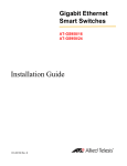
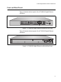
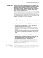
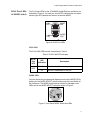
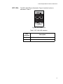
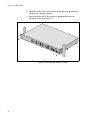
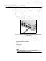
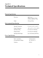
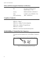
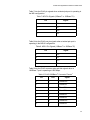
AT-9000/28 Managed Layer 2 GE ecoSwitch Installation Guide 613-001058 Rev. A Copyright 2008 Allied Telesis, Inc. All rights reserved. No part of this publication may be reproduced without prior written permission from Allied Telesis, Inc. Allied Telesis and the Allied Telesis logo are trademarks of Allied Telesis, Incorporated. All other product names, company names, logos or other designations mentioned herein are trademarks or registered trademarks of their respective owners. Allied Telesis, Inc. reserves the right to make changes in specifications and other information contained in this document without prior written notice. The information provided herein is subject to change without notice. In no event shall Allied Telesis, Inc.be liable for any incidental, special, indirect, or consequential damages whatsoever, including but not limited to lost profits, arising out of or related to this manual or the information contained herein, even if Allied Telesis, Inc. has been advised of, known, or should have known, the possibility of such damages. Electrical Safety and Emissions Standards This product meets the following standards. U.S. Federal Communications Commission Radiated Energy Note: This equipment has been tested and found to comply with the limits for a Class A digital device pursuant to Part 15 of FCC Rules. These limits are designed to provide reasonable protection against harmful interference when the equipment is operated in a commercial environment. This equipment generates, uses, and can radiate radio frequency energy and, if not installed and used in accordance with this instruction manual, may cause harmful interference to radio communications. Operation of this equipment in a residential area is likely to cause harmful interference in which case the user will be required to correct the interference at his own expense. Note: Modifications or changes not expressly approved of by the manufacturer or the FCC, can void your right to operate this equipment. Industry Canada This Class A digital apparatus complies with Canadian ICES-003. Cet appareil numérique de la classe A est conforme à la norme NMB-003 du Canada. RFI Emissions FCC Class A, EN55022 Class A, VCCI Class A, C-TICK, CE Warning: In a domestic environment this product may cause radio interference in which case the user may be required to take adequate measures. EMC (Immunity) EN55024, EN61000-3-2, EN61000-3-3 Electrical Safety EN60950-1 (TUV), UL 60950-1 (CULUS) Laser Safety EN60825 3 Translated Safety Statements Important: The indicates that a translation of the safety statement is available in a PDF document titled “Translated Safety Statements” (613-000990) posted on the Allied Telesis website at www.alliedtelesis.com. This document is also included with the documentation CD that is shipped with the product. 4 Contents Contents ...............................................................................................................................................................................5 Preface ..................................................................................................................................................................................7 Safety Symbols Used in this Document..................................................................................................................................8 Where to Find Web-based Guides .........................................................................................................................................9 Contacting Allied Telesis ......................................................................................................................................................10 Online Support ..............................................................................................................................................................10 Email and Telephone Support .......................................................................................................................................10 Returning Products........................................................................................................................................................10 For Sales or Corporate Information ...............................................................................................................................10 Warranty ........................................................................................................................................................................10 Management Software Updates ....................................................................................................................................10 Chapter 1: Overview ..........................................................................................................................................................11 Switch Features ....................................................................................................................................................................12 Front and Back Panels .........................................................................................................................................................13 Gigabit Ethernet Ports ..........................................................................................................................................................14 Twisted Pair Ports .........................................................................................................................................................14 Uplink Ports ...................................................................................................................................................................15 RS-232 Console Port ....................................................................................................................................................15 LEDs .....................................................................................................................................................................................16 System LEDs.................................................................................................................................................................16 RJ-45 Port LEDs & MODE Switch.................................................................................................................................17 SFP LEDs......................................................................................................................................................................19 ecoSwitch .............................................................................................................................................................................20 Ethernet Switching Basics ....................................................................................................................................................21 MAC Address Table ......................................................................................................................................................21 Duplex Mode .................................................................................................................................................................22 Auto MDI/MDI-X ............................................................................................................................................................................22 Store and Forward.........................................................................................................................................................22 Back Pressure and Flow Control ...................................................................................................................................22 Chapter 2: Installing the Switch .......................................................................................................................................25 Reviewing Safety Precautions ..............................................................................................................................................26 Selecting a Site.....................................................................................................................................................................28 Twisted Pair and Fiber Optic Cable Specifications...............................................................................................................29 Twisted Pair Cable Specifications .................................................................................................................................29 Optional Transceiver Cable Specifications....................................................................................................................29 Unpacking the Switch ...........................................................................................................................................................30 Installing the Switch in a Rack ..............................................................................................................................................31 Installing Optional Transceivers............................................................................................................................................33 Installing an SFP Transceiver .......................................................................................................................................33 Cabling the Twisted Pair or Fiber Optic Ports.......................................................................................................................35 Applying AC Power...............................................................................................................................................................36 Starting a Local Management Session .................................................................................................................................37 Warranty Registration ...........................................................................................................................................................39 5 Contents Chapter 3: Troubleshooting ..............................................................................................................................................41 Power LED is Off ..................................................................................................................................................................42 Twisted Pair Port Link LED is Off..........................................................................................................................................43 Fiber Optic Port Link LED is Off............................................................................................................................................44 Cannot Establish a Local (Out-of-Band) Management Session ...........................................................................................45 Appendix A: Technical Specifications .............................................................................................................................47 Physical Specifications .........................................................................................................................................................47 Environmental Specifications................................................................................................................................................47 Power Specifications.............................................................................................................................................................47 Safety and Electromagnetic Emissions Certifications...........................................................................................................48 Compliance Standards..........................................................................................................................................................48 10/100/1000Base-T Twisted Pair Port Connectors...............................................................................................................48 Console Port Pinouts ............................................................................................................................................................50 6 Preface This guide provides the hardware installation instructions for you to install the AT-9000/28 Gigabit Ethernet ecoSwitch. This preface contains the following sections: “Safety Symbols Used in this Document” on page 8 “Where to Find Web-based Guides” on page 9 “Contacting Allied Telesis” on page 10 7 Preface Safety Symbols Used in this Document This document uses the safety symbols defined in Table 1. Table 1. Safety Symbols Symbol 8 Meaning Description Caution Performing or omitting a specific action may result in equipment damage or loss of data. Warning Performing or omitting a specific action may result in electrical shock. AT-9000/28 Gigabit Ethernet ecoSwitch Installation Guide Where to Find Web-based Guides The installation and user guides for all Allied Telesis products are available in portable document format (PDF) on our web site at www.alliedtelesis.com. You can view the documents online or download them onto a local workstation or server. 9 Preface Contacting Allied Telesis This section provides Allied Telesis contact information for technical support as well as sales or corporate information. Online Support You can request technical support online by accessing the Allied Telesis Knowledge Base from the following web site: www.alliedtelesis.com/support. You can use the Knowledge Base to submit questions to our technical support staff and review answers to previously asked questions. Email and Telephone Support For Technical Support via email or telephone, refer to the Allied Telesis web site: www.alliedtelesis.com. Select your country from the list displayed on the website. Then select the appropriate menu tab. Returning Products Products for return or repair must first be assigned a Return Materials Authorization (RMA) number. A product sent to Allied Telesis without a RMA number will be returned to the sender at the sender’s expense. To obtain an RMA number, contact the Allied Telesis Technical Support group at our web site: www.alliedtelesis.com/support/rma. Select your country from the list displayed on the website. Then select the appropriate menu tab. For Sales or Corporate Information Warranty Management Software Updates You can contact Allied Telesis for sales or corporate information at our web site: www.alliedtelesis.com. Select your country from the list displayed on the website. Then select the appropriate menu tab. The AT-9000/28 Gigabit Ethernet ecoSwitch has a Lifetime Warranty (two years fan and PSU). Go to www.alliedtelesis.com/warranty for the specific terms and conditions of the warranty and for warranty registration. New releases of management software for our managed products are available from either of the following Internet sites: Allied Telesis web site: www.alliedtelesis.com Allied Telesis FTP server: ftp://ftp.alliedtelesis.com If you prefer to download new software from the Allied Telesis FTP server from your workstation’s command prompt, you will need FTP client software and you must log in to the server. Enter “anonymous” for the user name and your email address for the password. 10 Chapter 1 Overview The AT-9000/28 Gigabit Ethernet ecoSwitch is designed to simplify the task of creating or expanding an Ethernet, Fast Ethernet, or Gigabit Ethernet network. This chapter contains the follows sections: “Switch Features” on page 12 “Front and Back Panels” on page 13 “Gigabit Ethernet Ports” on page 14 “LEDs” on page 16 “Ethernet Switching Basics” on page 21 11 Overview Switch Features The features of the AT-9000/28 Gigabit Ethernet ecoSwitch include: 12 28 10/100/1000Base-T copper ports with RF-45 connectors 4 SFP slots RS232 Console port with RJ-45 connector Port status LEDs Low power mode push-button ecoSwitch MODE selection switch Auto MDI/MDI-X on the twisted pair ports IEEE 802.3i, 3u, and 3z compliant IEEE 802.3x flow control in full-duplex operation; back pressure in half-duplex operation and pause frame flow control in full duplex mode Store and forward switching mode MAC address table capacity of up to 8K addresses with automatic aging 16MB flash memory with 128MB RAM AT-S100 Management Software with a command line interface for local or remote management and a web browser interface for remote management Compliant with European, China and other RoHS standards AT-9000/28 Gigabit Ethernet ecoSwitch Installation Guide Front and Back Panels Figure 1 illustrates the front panel of the AT-9000/28 Gigabit Ethernet ecoSwitch. 25 27 25R 27R AT-9000/28 Gigabit Ethernet Switch with 4 Combo SFP Ports MODE PWR COL SYS SPD CONSOLE DUP ACT SELECT 26 28 26R 28R RS-232 1451 Figure 1. AT-9000/28 Gigabit Ethernet ecoSwitch Front Panel Figure 2 illustrates the back panel of the AT-9000/28 Gigabit Ethernet ecoSwitch. 100-240 VAC~ 1452 Figure 2. AT-9000/28 Gigabit Ethernet ecoSwitch Back Panel 13 Overview Gigabit Ethernet Ports The AT-9000/28 Gigabit Ethernet ecoSwitch features 24 twisted pair 10/ 100/1000Base-T ports, and four combo SFP/copper ports. Twisted Pair Ports The twisted pair ports feature 8-pin RJ-45 connectors. (For the port pinouts, refer to “10/100/1000Base-T Twisted Pair Port Connectors” on page 48.) The ports on the AT-9000/28 Gigabit Ethernet ecoSwitch are 1000Base-T, 100Base-TX and 10Base-T compliant and are capable of 1000 megabits per second (Mbps), 100 Mbps and 10 Mbps speeds. The ports are IEEE 802.3u Auto-Negotiation compliant. With AutoNegotiation enabled, the switch automatically matches the highest possible common speed between each switch port and each end node. For example, if an end node is capable of only 1000 Mbps, the switch sets the port connected to the end node to 1000 Mbps. The default setting for the twisted pair ports is Auto-Negotiate, which automatically determines the duplex mode setting. Each twisted pair port on the switches is capable of operating in either half- or full-duplex mode. Note In order for the switch to set the duplex mode for each port correctly, the end nodes that you connect to the switch ports should also use Auto-Negotiation. Otherwise, a duplex mode mismatch can occur, affecting network performance. For further information, refer to “Duplex Mode” on page 21. Each twisted pair port has a maximum operating distance of 100 m (328 feet). For 10 Mbps operation, Category 3 or better 100 ohm shielded or unshielded twisted pair cabling is required. For 100 or 1000 Mbps operation, Category 5 and Enhanced Category 5 (5E) or better 100 ohm shielded or unshielded twisted pair cabling is required. For cable specifications, go to “Twisted Pair and Fiber Optic Cable Specifications” on page 29 14 AT-9000/28 Gigabit Ethernet ecoSwitch Installation Guide Uplink Ports The switch has four combo pairs of uplink ports, each consisting of one slot for a SFP transceiver and an redundant 10/100/1000 Base-T twisted pair port .The ports are numbered 25 through 28 on the AT-9000/28 Gigabit Ethernet ecoSwitch. The twisted pair ports in each of the combo pairs are identified with the letter “R” for “Redundant” as part of their number on the front faceplate of the unit. In each combo pair, you can use one port pair at a time. A link on an SFP transceiver takes precedence over a link on the corresponding redundant twisted pair port. If an SFP transceiver is installed and has a link to an end node, the twisted pair port in the pair is inactive. If the SFP slot is empty or if an SFP module is inserted and does not have an active link, the 10/100/ 1000Base-T twisted pair port of the pair will be active. Note When the copper port is inactive, it may have a link to its end node. However, the port will not pass traffic in this mode. Follow these guidelines when using these SFP slots and reduncant ports: Only one port in a pair can be active at a time — either the SFP module or its corresponding twisted pair port. The twisted pair port is the active port when its SFP slot is empty, or when a SFP module is installed but has not established a link to an end node. A twisted pair port automatically changes to the inactive mode when a SFP module in the corresponding slot establishes a link with an end node. A twisted pair port automatically transitions back to the active status when the link is down on the corresponding SFP module. In nearly all cases, a twisted pair port and a SFP module share the same configuration settings, including port settings, VLAN assignments, access control lists, and spanning tree. An exception to the shared settings is port speed. If you disable AutoNegotiation on a twisted pair port and set the speed and duplex mode manually, the speed reverts to Auto-Negotiation when a SFP module establishes a link with an end node. RS-232 Console Port The RS-232 Console port uses the management cable supplied with the switch. Through the Console port you can connect to the switch and use the CLI-based AT-S100 Mangement Software user interface. 15 Overview LEDs System LEDs There are two system LEDs, the Power LED and SYS LED as shown in the following figure: PWR SYS Figure 3 Power and System LEDs The power supply port and system LED indications are described in the following table: Table 2 Power Supply LED Indications LED Description Power SYS 16 LED Indication Description Green System is powered up (power on) Off System is not powered up (power off) Green System is operational AT-9000/28 Gigabit Ethernet ecoSwitch Installation Guide RJ-45 Port LEDs & MODE Switch The RJ-45 port LEDs for the AT-9000/28 Gigabit Ethernet ecoSwitch are illustrated in Figure 4. On each port, the left LED indicates the Link status and the right LED indicates the status of a selected MODE. LINK LED MODE LED LINK LED MODE LED 1467 Figure 4. RJ-45 Port LEDs LINK LED The RJ-45 LINK LED function is described in Table 3: Table 3. RJ-45 LINK LED Indication RJ-45 Port LED Left LED LED Indication Solid Green Off Description A link is established on the port. No link is established on the port. MODE LED You can choose the port parameter displayed on the port MODE LED by pushing the the MODE SELECT switch located next to the ecoSwitch on the front panel. The MODE function that is selected is indicated on the LEDs next to the MODE SELECT switch as shown in Figure 5.. AT-900 Gigabit Etherne MODE COL SPD DUP ACT SELECT Figure 5. Front Panel MODE Switch and LEDs 17 Overview The RJ-45 Port Mode LED indications are described in Table 4. Each port MODE is selected by the MODE SELECT switch . Table 4 RJ-45 Port LED MODE Indications RJ-45 Port LED Port MODE LED Indication Solid Green COL Right LED SPD Off Data collisions are occurring on the port. No data collisions are occurring on the port. Solid Green Link is established at 1000Mbps. Solid Amber Link is established at 100Mbps. Off Link is established in 10Mbps. Solid Green A Full Duplex mode connection is established. FDX Off A Half Duplex mode connection is established. ACT Flashing Green Off 18 Description Port is transmitting and/or receiving data (default mode). No activity is established. AT-9000/28 Gigabit Ethernet ecoSwitch Installation Guide SFP LEDs The SFP LINK LEDs are illustrated in Figure 6 and their function is described in Table 5: 25 27 26 28 LINK LEDs Figure 6. SFP LINK LEDs Table 5. SFP LINK LED Indication LED Indication Solid Green Off Description A link is established on the port. No link is established on the port. 19 Overview ecoSwitch The ecoSwitch button on the front panel of the AT-9000/28 Gigabit Ethernet ecoSwitch enables the low power mode. This mode allows you to conserve power by turning off the port and MODE LEDs when they are not required. To toggle the LEDs on or off, press the ecoSwitch button illustrated in Figure 7 next to the SELECT MODE button. The LPM feature does not affect the network operations of the switch or the Power and Sys LEDs. AT-900 Gigabit Etherne MODE COL SPD DUP ACT SELECT 1465 Figure 7. Front Panel ecoSwitch 20 AT-9000/28 Gigabit Ethernet ecoSwitch Installation Guide Ethernet Switching Basics An Ethernet switch interconnects network devices, such as workstations, printers, routers, and other Ethernet switches, so that they can communicate with each other by sending and receiving Ethernet frames. MAC Address Table Every hardware device on your network has a unique MAC address. This address is assigned to the device by the device’s manufacturer. For example, when you install a Network Interface Card (NIC) in a computer so that you can connect it to the network, the NIC already has a MAC address assigned to it by its manufacturer. The MAC address table in the AT-9000/28 Gigabit Ethernet ecoSwitch can store up to 8K MAC addresses. The switch uses the table to store the MAC addresses of the network end nodes connected to the ports, along with the port number on which each address was learned. A switch learns the MAC addresses of the end nodes by examining the source address of each packet received on a port. It adds the address and port on which the packet was received to the MAC table if the address had not already been entered in the table. The result is a table that contains all the MAC addresses of the devices that are connected to the switch’s ports, and the port number where each address was learned. When the switch receives a packet, it also examines the destination address and, by referring to its MAC address table, determines the port on which the destination end node is connected. It then forwards the packet to the appropriate port and on to the end node. This increases network bandwidth by limiting each frame to the appropriate port when the intended end node is located, freeing the other switch ports for receiving and transmitting data. If the switch receives a packet with a destination address that is not in the MAC address table, it floods the packet to all the ports on the switch. If the ports have been grouped into virtual LANs, the switch floods the packet only to those ports which belong to the same VLAN as the port on which the packet was received. This prevents packets from being forwarded into inappropriate LAN segments, decreasing network security. When the destination end node responds, the switch adds its MAC address and port number to the table. If the switch receives a packet with a destination address that is on the same port on which the packet was received, it discards the packet without forwarding it on to any port. Since both the source end node and the destination end node for the packet are located on the same port on the switch, there is no reason for the switch to forward the packet. 21 Overview Duplex Mode Duplex mode refers to how an end node receives and transmits data. If an end node can receive or transmit data, but not both simultaneously, it is operating in what is referred to as half-duplex mode. If an end node can both receive and transmit data simultaneously, the end node is said to be operating in full-duplex mode. Naturally, an end node capable of operating in full-duplex can handle data much faster than an end node that can only operate in half-duplex mode. The twisted pair ports on the AT-9000/28 Gigabit Ethernet ecoSwitch can operate in either half-or full-duplex mode. They are IEEE 802.3ucompliant and use Auto-Negotiation to set the duplex mode setting for you automatically. For Auto-Negotiation to operate properly on a switch, the end nodes connected to the switch should also use Auto-Negotiation. If an end node does not have this feature and has a fixed duplex mode of full-duplex, the result will be a duplex mode mismatch between the end node and a switch port. A port on the Gigabit Ethernet switch connected to an end node with a fixed duplex mode of full-duplex will operate at only half-duplex. This results in the end node using full-duplex and the switch port using halfduplex. This can produce network performance problems. If you encounter this situation, you must configure the port on the end node to use Auto-Negotiation or, if it lacks that feature, to half-duplex. Auto MDI/MDI-X The auto-MDI/MDI-X feature on the twisted pair ports automatically configures the MDI/MDI-X setting when a link is established with an end node. Available when a port is at the default setting of Auto-Negotiation, this feature allows you to use a straight-through twisted pair cable when connecting any type of network device to a port. Disabling Auto-Negotiation on a port and setting the speed and duplex mode manually also disables the auto-MDI/MDI-X feature. A port where Auto-Negotiation has been disabled defaults to MDI-X. Disabling AutoNegotiation may require manually configuring a port’s MDI/MDI-X setting or using a crossover cable. For instructions on how to configure a port, refer to the AT-S100 Management Software User’s Guide. Store and Forward Back Pressure and Flow Control 22 The AT-9000/28 Gigabit Ethernet ecoSwitch uses store and forward as the method for receiving and transmitting frames. When a Ethernet frame is received on a switch port, the switch does not retransmit the frame out the destination port until it has received the entire frame and stored the frame in a port buffer. It then examines the frame to determine if it is a valid frame. Invalid frames, such as fragments or runts, are discarded by the switch. This insures that only valid frames are transmitted out the switch ports and that damaged frames are not propagated on your network. To maintain the orderly movement of data between the end nodes, an Ethernet switch may periodically need to signal an end node to stop AT-9000/28 Gigabit Ethernet ecoSwitch Installation Guide sending data. This can occur under several circumstances. For example, if two end nodes are operating at different speeds, the switch, while transferring data between the end nodes, might need to instruct the faster end node to stop transmitting data to allow the slower end node to catch up. An example of this would be when a server operating at 100 Mbps is sending data to a workstation operating at only 10 Mbps. How a switch signals an end node to stop transmitting data differs depending on the speed and duplex mode of the end node and switch port. A twisted pair port operating at 100 Mbps and half-duplex mode will stop an end node from transmitting data by forcing a collision. A collision on an Ethernet network occurs when two end nodes attempt to transmit data using the same data link at the same time. A collision causes end nodes to stop sending data. When the switch needs to stop a 100 Mbps, half-duplex end node from transmitting data, it forces a collision on the data link, which stops the end node. When the switch is ready to receive data again, the switch stops forcing collisions. This is referred to as back pressure. A port operating at 100 Mbps and full-duplex mode uses PAUSE frames, as specified in the IEEE 802.3x standard, to stop the transmission of data from an end node. Whenever the switch wants an end node to stop transmitting data, it issues this frame. The frame instructs the end node to cease transmission. The switch continues to issue PAUSE frames until it is ready again to receive data from the end node. This is referred to as flow control. The AT-9000/28 Gigabit Ethernet ecoSwitch supports back pressure flow control in half duplex mode and pause frame flow control in full duplex mode. 23 Overview 24 Chapter 2 Installing the Switch This chapter contains the installation procedures for the switch. The chapter contains the following sections: “Reviewing Safety Precautions” on page 26 “Selecting a Site” on page 28 “Twisted Pair and Fiber Optic Cable Specifications” on page 29 “Unpacking the Switch” on page 30 “Installing the Switch in a Rack” on page 31 “Installing Optional Transceivers” on page 33 “Cabling the Twisted Pair or Fiber Optic Ports” on page 35 “Applying AC Power” on page 36 “Starting a Local Management Session” on page 37 “Warranty Registration” on page 39 25 Chapter 2 - Installing the Switch Reviewing Safety Precautions Please review the following safety precautions before you begin to install the switch or any of its components. Note The indicates that a translation of the safety statement is available in a PDF document titled “Translated Safety Statements” (613-000990) posted on the Allied Telesis website at www.alliedtelesis.com. This document is also included with the documentation CD that is shipped with the product. Note Refer to the documentation that comes with an SFP module to determine whether it is a Class 1 LED or a Class 1 Laser product. Warning: Class 1 Laser product. L1 Warning: Do not stare into the laser beam. L2 Warning: Class 1 LED product. L3 Warning: To prevent electric shock, do not remove the cover. No user-serviceable parts inside. This unit contains hazardous voltages and should only be opened by a trained and qualified technician. To avoid the possibility of electric shock, disconnect electric power to the product before connecting or disconnecting the LAN cables. E1 Warning: Do not work on equipment or cables during periods of lightning activity. E2 Warning: Power cord is used as a disconnection device. To deenergize equipment, disconnect the power cord. E3 Warning: Class I Equipment. This equipment must be earthed. The power plug must be connected to a properly wired earth ground socket outlet. An improperly wired socket outlet could place hazardous voltages on accessible metal parts. E4 26 AT-9000/28 Gigabit Ethernet ecoSwitch Installation Guide Pluggable Equipment. The socket outlet shall be installed near the equipment and shall be easily accessible. E5 Caution: Air vents must not be blocked and must have free access to the room ambient air for cooling. E6 Warning: Operating Temperature. This product is designed for a maximum ambient temperature of 40° degrees C. E7 All Countries: Install product in accordance with local and National Electrical Codes. E8 Circuit Overloading: Consideration should be given to the connection of the equipment to the supply circuit and the effect that overloading of circuits might have on overcurrent protection and supply wiring. Appropriate consideration of equipment nameplate ratings should be used when addressing this concern. E21 Warning: Mounting of the equipment in the rack should be such that a hazardous condition is not created due to uneven mechanical loading. E25 If installed in a closed or multi-unit rack assembly, the operating ambient temperature of the rack environment may be greater than the room ambient temperature. Therefore, consideration should be given to installing the equipment in an environment compatible with the manufacturer’s maximum rated ambient temperature (Tmra). E35 Caution: Installation of the equipment in a rack should be such that the amount of air flow required for safe operation of the equipment is not compromised. E36 Warning: Reliable earthing of rack-mounted equipment should be maintained. Particular attention should be given to supply connections other than direct connections to the branch circuits (e.g., use of power strips). E37 Caution: The unit does not contain serviceable components. Please return damaged units for servicing. 27 Chapter 2 - Installing the Switch Selecting a Site Observe the following requirements when choosing a site for the switch. 28 If you plan to install the switch in an equipment rack, check to be sure the rack is safely secured and will not tip over. Devices in a rack should be installed starting at the bottom, with the heavier devices near the bottom of the rack. If you are installing the switch on a table, be sure the table is level and secure. The power outlet for the switch should be located near the unit and be easily accessible. The site should provide easy access to the ports on the front of the switch. This will make it easy for you to connect and disconnect cables, as well as view the switch’s LEDs. To allow proper cooling of the switch, air flow around the unit and through its vents on the side and rear should be unrestricted. Do not place objects on top of the switch. Do not expose the switch to moisture or water. Make sure that the site is a dust-free environment. Use dedicated power circuits or power conditioners to supply reliable electrical power to the network devices. AT-9000/28 Gigabit Ethernet ecoSwitch Installation Guide Twisted Pair and Fiber Optic Cable Specifications Twisted Pair Cable Specifications Table 6 lists the cabling specifications for the 10/100/1000Base-T twisted pair ports. Table 6. Twisted Pair Cabling and Distances Speed Optional Transceiver Cable Specifications Cable Type Maximum Operating Distance 10 Mbps Standard TIA/EIA 568-B-compliant Category 3 or better shielded or unshielded cabling with 100 ohm impedance and a frequency of 16 MHz. 100 m (328 ft) 100 Mbps Standard TIA/EIA 568-A-compliant 100 m (328 ft) Category 5 or TIA/EIA 568-Bcompliant Enhanced Category 5 (Cat 5e) shielded or unshielded cabling with 100 ohm impedance and a frequency of 100 MHz. 1000 Mbps Standard TIA/EIA 568-A-compliant 100 m (328 ft) Category 5 or TIA/EIA 568-Bcompliant Enhanced Category 5 (Cat 5e) shielded or unshielded cabling with 100 ohm impedance and a frequency of 100 MHz. The cable specifications for the optional SFP transceivers can be found in the installation guide shipped with the transceiver. 29 Chapter 2 - Installing the Switch Unpacking the Switch To unpack the switch, perform the following procedure: 1. Remove all components from the shipping package. Note Store the packaging material in a safe location. You must use the original shipping material if you need to return the unit to Allied Telesis. 2. Place the switch on a level, secure surface. 3. Make sure the following components are included in your switch package. If any item is missing or damaged, contact your Allied Telesis sales representative for assistance. 30 One AT-9000/28 Gigabit Ethernet ecoSwitch Two rack-mount brackets Eight flathead Phillips rack-mount bracket screws AC power cord (AC switches only; Americas, EU, Australia, and UK only) Management cable for local management Documentation CD AT-9000/28 Gigabit Ethernet ecoSwitch Installation Guide Installing the Switch in a Rack Perform the following procedure to install the switch in a standard 19-inch rack: Note Steps 1, 2, and 3 are optional. They remove the snap-on plastic feet from the bottom of a switch. The feet can be left on. 1. Place the unit upside down on a level, secure surface. 2. Using a flat-head screwdriver, remove the snap-on plastic feet from the bottom of the switch, as shown in Figure 8. Figure 8. Removing the Feet 3. Turn the switch over. 4. Attach a rack-mount bracket to one side of the switch using four of the screws that come with the switch, as shown in . 25 27 25R 27R 26 28 26R PWR MOD SYS COL AT-9 00 E Gig SPD 28R abit Eth ern 0/28 et Swi tch DUP SEL with CON SOL E ACT 4 Com bo SFP Por ts ECT RS- 232 1462 Figure 9. Attaching Rack-Mount Brackets 31 Chapter 2 - Installing the Switch 5. Install the second rack-mount bracket on the other side of the switch using the four remaining screws. 6. Mount the switch in the 19-inch rack using standard screws (not provided), as shown in Figure 10. 25 27 25R 27R 26 28 PWR 26R SYS 28R AT9 MO DE Gig COL SPD 000 /2 ern et Sw 8 abi t Eth itch DUP ACT SEL with CONS OL E 4 Co mb o SF P Po rts ECT RS-23 2 1463 Figure 10. Mounting the Switch in a Rack 32 AT-9000/28 Gigabit Ethernet ecoSwitch Installation Guide Installing Optional Transceivers Review the following guidelines before installing an optional SFP transceiver in the switch: A transceiver can be hot-swapped. The switch can be powered on when you install a transceiver. Install the transceiver before connecting its network cable. Fiber optic transceivers are dust sensitive. When a fiber optic cable is not installed, or when you store the transceiver, always keep the plug in the optical bores. When you do remove the plug, keep it for future use. Unnecessary removal or insertion of a transceiver can lead to premature failure. The SFP slots are paired with twisted pair ports. For operational information, refer to “Twisted Pair Ports” on page 14. Warning A transceiver can be damaged by static electricity. Be sure to observe all standard electrostatic discharge (ESD) precautions, such as wearing an antistatic wrist strap, to avoid damaging the device. Installing an SFP Transceiver To install an SFP transceiver in the AT-9000/28 Gigabit Ethernet ecoSwitch, perform the following procedure: 1. Remove the transceiver from its shipping container and store the packaging material in a safe location. 2. Position the transceiver with the label facing up. 33 Chapter 2 - Installing the Switch 3. Slide the transceiver into the slot until it clicks into place as shown in Figure 11. 25 27 25R 27R 26 28 PWR 26R SYS MO DE COL AT G iga SPD DUP 28R ACT SEL ECT 1456 Figure 11. Inserting the Transceiver 4. Remove the dust plug from a transceiver slot on the switch, as shown in Figure 12. 25 27 25R 27R 26 28 PWR 26R SYS MO DE COL AT G iga SPD 28R DUP ACT SEL ECT 1457 Figure 12. Removing the SFP Dust Cap 5. Verify that the handle on the SFP transceiver is in the upright position, as shown in Figure 12, to prevent inadvertently removing the transceiver. 6. Repeat this procedure to install another SFP transceiver or go to “Cabling the Twisted Pair or Fiber Optic Ports” on page 35. For SFP optical and cabling specifications, consult the documentation shipped with the module. 34 AT-9000/28 Gigabit Ethernet ecoSwitch Installation Guide Cabling the Twisted Pair or Fiber Optic Ports Observe the following guidelines when connecting a twisted pair or fiber optic cable to a port on the switch: The connector on the cable should fit snugly into the port on the switch. The tab on the connector should lock the connector into place. Because the twisted pair ports on the switch are auto-MDI/MDI-X, any type of network device can be connected to a port on the switch using a straight-through twisted pair cable. If you disable Auto-Negotiation on the port, the port defaults to MDI-X. For instructions on how to configure a port, refer to the AT-S100 Management Software User’s Guide. If your network topology contains a loop where two or more network devices can communicate with each other over more than one network path, do not connect the network cables forming the loop until after you have activated a spanning tree protocol on the switch. Data loops can adversely affect network performance. For background information on the different types of spanning tree protocols supported by the switch, refer to the AT-S100 Management Software User’s Guide. If you are creating a port trunk, you must configure the switch’s management software before connecting the cables of the trunk to the switch. Otherwise, a network loop will result which can adversely affect network performance. For background information on the types of port trunks supported by the switch, refer to the AT-S100 Management Software User’s Guide. In order for a switch port to successfully Auto-Negotiate its duplex mode with an end node, the end node should also be using AutoNegotiation. Otherwise, a duplex mode mismatch can occur. A switch port using Auto-Negotiation defaults to half-duplex if it detects that the end node is not using Auto-Negotiation. This can result in a mismatch if the end node is operating at a fixed duplex mode of full-duplex. To avoid this problem, disable Auto-Negotiation on a switch port and set the port’s speed and duplex mode manually if the end node has a fixed duplex mode of full-duplex. 35 Chapter 2 - Installing the Switch Applying AC Power To apply AC power to the switch, perform the following procedure: 1. Plug the power cord into the AC power connector on the back panel of the unit (see Figure 13). Warning: Power cord is used as a disconnection device. To deenergize equipment, disconnect the power cord. E3 . 100 -240 VAC ~ 1461 Figure 13. Connecting the AC Power Cord 2. Connect the other end of the power cord to an appropriate AC power outlet. For power specifications for the switch, refer to “Power Specifications” on page 47. 3. When power is applied, the switch begins to load the AT-S100 Management Software. The loading process takes approximately 20 to 30 seconds to complete. The switch is now ready for network operations. No further installation steps are required if the default parameter settings of the switch, listed in the AT-S100 Management Software User’s Guide, are adequate for your network. If you want to manage the switch, refer to “Starting a Local Management Session” on page 37. 36 AT-9000/28 Gigabit Ethernet ecoSwitch Installation Guide Starting a Local Management Session The procedure in this section explains how to start a local (out-of-band) management session using the RJ-45 terminal port on the switch. You can use a local management session to configure the switch’s operating parameters and view performance and error statistics. To start a local management session, perform the following procedure: 1. Connect the RJ-45 end of the management cable included with the AT-9000/28 Gigabit Ethernet ecoSwitch to the Console Port on the front panel of the switch, as shown in Figure 14. 27 25R 27R 28 PWR 26R SYS MO DE COL AT90 Gig abit Eth SPD 28R DUP ACT 00/ ern et S 28 witc hw CON ith SOL E 4C om bo SFP SEL ECT RS-2 Port s 32 1460 Figure 14. Connecting the Management Cable to the RJ-45 Console Port on the Switch 2. Connect the other end of the cable to an RS-232 port on a terminal or a personal computer with a terminal emulation program. 3. Configure the terminal or terminal emulation program as follows: Baud rate: Default is 9600 bps Data bits: 8 Parity: None Stop bits: 1 Flow control: None Note The port settings are for a DEC VT100 or ANSI terminal, or an equivalent terminal emulator program. 37 Chapter 2 - Installing the Switch 4. Press Enter. You are prompted for a user name and password. 5. To configure the switch settings, enter “manager” as the user name. The default password for manager access is “friend.” To just view the settings, enter “operator” as the user name. The default password for operator access is “operator.” User names and passwords are case sensitive. 6. The local management session starts and the command line interface (CLI) prompt is displayed, as shown in Figure 15. Figure 15. CLI Prompt For information about the command line interface, refer to the AT-S100 Management Software User’s Guide. 38 AT-9000/28 Gigabit Ethernet ecoSwitch Installation Guide Warranty Registration For warranty information, go to “Warranty” on page 10 or the Allied Telesis web site at www.alliedtelesis.com. 39 Chapter 2 - Installing the Switch 40 Chapter 3 Troubleshooting This chapter contains information about how to troubleshoot the switch in the event a problem occurs. Note If you are unable to resolve a problem after following the instructions in this chapter, contact Allied Telesis Technical Support for assistance. Refer to “Contacting Allied Telesis” on page 13 for contact information. 41 Chapter 3 - Troubleshooting Power LED is Off Check the PWR LED on the front of the switch. If the LED is off, indicating that the unit is not receiving power, do the following: 42 Make sure the power cord is securely connected to the power source and to the AC connector on the back panel of the switch. Verify that the power outlet has power by connecting another device to it. Try connecting the unit to another power source. Try using a different power cord. Check that the voltage from the power source is within the required levels for your region. AT-9000/28 Gigabit Ethernet ecoSwitch Installation Guide Twisted Pair Port Link LED is Off When a twisted pair port on the switch is connected to a properly operating end node, the Link LED for the port should be on. If a Link LED is off, do the following: Verify that the ecoSwitch setting on the front panel is not set to the power saving mode by pressing the ecoSwitch push- button on the front panel. Verify that the end node connected to the port is powered ON and is operating properly. Check that the twisted pair cable is securely connected to the port on the switch and to the port on the end node. Make sure that the twisted pair cable does not exceed 100m (328 ft). Verify that you are using the appropriate category of twisted pair cable. For information, refer to Table 6 on page 29. Determine if a crossover cable is required. Since the twisted pair ports feature auto MDI/MDI-X, you should be able to use a straight-through cable regardless of the type of device you connect to a port. However, if you disable Auto-Negotiation on a port and set a port’s speed and duplex mode manually, the port defaults to MDI-X. Disabling AutoNegotiation may require manually configuring a port’s MDI/MDI-X setting or using a crossover cable. Make sure that the operating parameters of the port on the switch are compatible with the end node to which the port is connected. This may require using the switch’s management software. If a switch port is using Auto-Negotiation, the default setting, to set its speed and duplex mode settings, the end node connected to the port should also be using Auto-Negotiation to prevent a duplex mode mismatch. This can occur because a switch port that is using AutoNegotiation will default to the half-duplex mode if it detects that the end node is not using Auto-Negotiation. If the end node is operating at a fixed duplex mode of full-duplex, the result will be a mismatch of settings on the two devices, with the switch port using half-duplex and the end node using full-duplex. To avoid this problem, you should disable Auto-Negotiation on a switch port and set the port’s speed and duplex mode manually if the end node has a fixed duplex mode of full-duplex. The switch has a bad cable detection feature that enables it to determine if a twisted pair cable has a electrical short that might cause a network loop. If the switch detects a bad cable on a port, it does not establish a link on that port. Try replacing the cable. 43 Chapter 3 - Troubleshooting Fiber Optic Port Link LED is Off When a fiber optic port on the switch is connected to a properly operating end node, the Link LED for the port should be on. If a Link LED is off, do the following: 44 Verify that the ecoSwitch setting on the front panel is not set to the power saving mode by pressing the ecoSwitch push- button on the front panel. Verify that the end node connected to the port is powered ON and is operating properly. Check that the fiber optic cable is securely connected to the port on the switch and the port on the end node. Check to be sure that the SFP transceiver is firmly inserted into the slot on the switch. Make sure that you are using the appropriate type of fiber optic cable and that the cable length does not exceed the allowed maximum distance. For cable specifications for an SFP module, refer to the installation instructions that ship with the module. Use a fiber optic tester to test the attenuation on the cable and the strength of the optical signal. For the operating specifications of the SFP module, refer to the installation instructions shipped with the module. Check that the operating specifications (for instance, wavelength and maximum operating distance) of the fiber optic port on the remote end node are compatible with the fiber optic port on the switch. Check to be sure that the fiber optic ports on the switch and on the end node are operating at the same speed and duplex mode. A fiber optic cable contains two separate fiber strands. One strand is for receiving data and the other is for transmitting data. When you connect a fiber optic cable to a port, be sure that the receive fiber connector is connected to the transmit connector on the remote end node, and that the transmit fiber connector is connected to the receive connector on the remote node. AT-9000/28 Gigabit Ethernet ecoSwitch Installation Guide Cannot Establish a Local (Out-of-Band) Management Session If you are unable to establish a local (out-of-band) management session with the switch through the terminal port on the front panel, do the following: Check to be sure that the RJ-45 connector of the serial management cable is securely connected to the Console port on the switch and the DB-9 connector is connected to the RS-232 port on the terminal or personal computer. Check to be sure that the operating parameters on the terminal or the terminal emulation program have been set correctly. The default settings for the RJ-45 serial terminal port are located in “Starting a Local Management Session” on page 37. 45 Chapter 3 - Troubleshooting 46 Appendix A Technical Specifications Physical Specifications Dimensions: (W x D x H) 440 mm x 256 mm x 44 mm (17.33 in x 10.08 in x 1.73 in) Weight: 3.62 kg (8.00 lbs) Environmental Specifications Operating Temperature: 0° C to 40° C (32° F to 104° F) Storage Temperature: -25° C to 70° C (-13° F to 158° F) Operating Humidity: 5% to 90% non-condensing Storage Humidity: 5% to 95% non-condensing Operating Altitude Range: Up to 3,000 meters (9,843 feet) Power Specifications Power Consumption: 45 watts maximum AC Input Electrical Ratings: 100 - 240V AC, 1A Frequency: 50/60 Hz 47 Appendix A: Technical Specifications Safety and Electromagnetic Emissions Certifications EMI FCC Class A, CISPR 22 Class A, EN55022 Class A, C-TICK Immunity EN55024, EN61000-3-2, EN61000-3-3 Safety UL 60950-1 (CULUS), EN60950-1 (TUV) Quality and Reliability: MTBF – 340,000 hours Compliance Standards IEEE 802.3 – 10Base-T IEEE 802.3u – 100Base-TX with Auto-Negotiation IEEE 802.3ab – 1000Base-TX Gigabit Ethernet IEEE 802.3z – Full Duplex IEEE 802.3x – Flow Control, Symmetric and Asymmetric 10/100/1000Base-T Twisted Pair Port Connectors This section lists the pin signals for the 10/100/1000Base-T twisted pair ports. Figure 16 illustrates the pin layout to an RJ-45 connector and port. 8 1 8 1 Figure 16. RJ-45 Connector and Port Pin Layout 48 AT-9400 Series Gigabit Ethernet Switches Installation Guide Table 7 lists the RJ-45 pin signals when a twisted pair port is operating in the MDI configuration. Table 7. MDI Pin Signals (10Base-T or 100Base-TX) Pin Signal 1 TX+ 2 TX- 3 RX+ 6 RX- Table 8 lists the RJ-45 port pin signals when a twisted pair port is operating in the MDI-X configuration. Table 8. MDI-X Pin Signals (10Base-T or 100Base-TX) Pin Signal 1 RX+ 2 RX- 3 TX+ 6 TX- Table 9 lists the RJ-45 connector pins and their signals when a 1000Base-T port is operating at 1000 Mbps. Table 9. RJ-45 1000Base-T Connector Pinouts1 Pin Pair Signal 1 1 TX and RX+ 2 1 TX and RX- 3 2 TX and RX+ 4 3 TX and RX+ 5 3 TX and RX- 6 2 TX and RX- 7 4 TX and RX+ 8 4 TX and RX- 1. Bi-directional data on each pair. 49 Appendix A: Technical Specifications Console Port Pinouts Table 10 lists the pin signals on the RJ-45 style serial terminal port. Table 10 Console Port Pinouts Pin 50 Signal 4 Ground 3 Transmit Data 6 Receive Data 7 No Connection 5 Ground 2 No Connection 8 No Connection 1 No Connection


![Installation Guide: AT-TQ2450 [Rev A] (PDF Version)](http://vs1.manualzilla.com/store/data/005654085_1-f326a5d33793ff2ec849a19a13c1dba6-150x150.png)