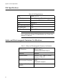
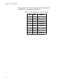
1
AT-GS900/8PS Gigabit Ethernet POE+ Switch AT-GS900/8PS Installation Guide PN 613-001687 Rev. A Copyright © 2012 Allied Telesis, Inc. All rights reserved. No part of this publication may be reproduced without prior written permission from Allied Telesis, Inc. Allied Telesis and the Allied Telesis logo are trademarks of Allied Telesis, Incorporated. All other product names, company names, logos or other designations mentioned herein are trademarks or registered trademarks of their respective owners. Allied Telesis, Inc. reserves the right to make changes in specifications and other information contained in this document without prior written notice. The information provided herein is subject to change without notice. In no event shall Allied Telesis, Inc. be liable for any incidental, special, indirect, or consequential damages whatsoever, including but not limited to lost profits, arising out of or related to this manual or the information contained herein, even if Allied Telesis, Inc. has been advised of, known, or should have known, the possibility of such damages. Electrical Safety and Emissions Standards This product meets the following standards. U.S. Federal Communications Commission Radiated Energy Note: This equipment has been tested and found to comply with the limits for a Class A digital device pursuant to Part 15 of FCC Rules. These limits are designed to provide reasonable protection against harmful interference when the equipment is operated in a commercial environment. This equipment generates, uses, and can radiate radio frequency energy and, if not installed and used in accordance with this instruction manual, may cause harmful interference to radio communications. Operation of this equipment in a residential area is likely to cause harmful interference in which case the user will be required to correct the interference at his own expense. Note: Modifications or changes not expressly approved of by the manufacturer or the FCC, can void your right to operate this equipment. Industry Canada This Class A digital apparatus meets all requirements of the Canadian Interference-Causing Equipment Regulations. Cet appareil numérique de la classe A respecte toutes les exigences du Règlement sur le matériel brouilleur du Canada. RFI Emissions FCC Part 15 Class A CISPR 22 Class A EN55022:2006/A:2007 Class A Warning: In a domestic environment this product may cause radio interference in which case the user may be required to take adequate measures. Immunity EN55024 Electrical Safety EN60950 (TUV) T-Mark UL 60950 (CULUS) C-TICK CE Environmental Compliance EU-RoHS compliant WEEE China RoHS compliant 3 Translated Safety Statements Important: The indicates that a translation of the safety statement is available in a PDF document titled “Translated Safety Statements” posted on the Allied Telesis website at www.alliedtelesis.com. 4 Contents Preface ................................................................................................................................................................................11 Symbol Conventions .....................................................................................................................................................12 Contacting Allied Telesis ...............................................................................................................................................13 Chapter 1: Overview ..........................................................................................................................................................15 Features ........................................................................................................................................................................16 General ..................................................................................................................................................................16 Twisted Pair Ports ..................................................................................................................................................16 LEDs ......................................................................................................................................................................16 PoE Ports ...............................................................................................................................................................16 SFP Slots ...............................................................................................................................................................16 Power over Ethernet ..............................................................................................................................................17 Installation Options.................................................................................................................................................17 Power Conservation ...............................................................................................................................................17 MAC Address Table ...............................................................................................................................................17 Dimensions ............................................................................................................................................................17 Operating Conditions .............................................................................................................................................17 Front and Back Panels ..................................................................................................................................................18 Twisted Pair Ports .........................................................................................................................................................19 Cable Specifications...............................................................................................................................................19 MDI/MDI-X Mode ...................................................................................................................................................19 Auto-Negotiation Mode ..........................................................................................................................................20 Flow Control and Back Pressure............................................................................................................................20 SFP Port ........................................................................................................................................................................21 LEDs..............................................................................................................................................................................22 Power Over Ethernet .....................................................................................................................................................25 PoE Standards .......................................................................................................................................................25 PoE Powered Device Classes ...............................................................................................................................26 PoE Power Budget .................................................................................................................................................26 PoE Port Prioritization ............................................................................................................................................27 PoE Guard Band ....................................................................................................................................................27 Exceeding PoE Power Budget ...............................................................................................................................27 Wiring Implementation ...........................................................................................................................................29 Power Supply ................................................................................................................................................................30 Chapter 2: Installation .......................................................................................................................................................31 Reviewing Safety Precautions.......................................................................................................................................32 Selecting a Site for the Switch.......................................................................................................................................34 Unpacking the Switch ....................................................................................................................................................35 Installing the Switch on a Desktop ................................................................................................................................37 Installing the Switch in an Equipment Rack...................................................................................................................38 Installing the Switch on a Wall.......................................................................................................................................40 Installing Optional SFP Transceiver ..............................................................................................................................43 Cabling the Switch.........................................................................................................................................................45 Powering On the Switch ................................................................................................................................................46 Chapter 3: Troubleshooting ..............................................................................................................................................47 Power LED OFF ............................................................................................................................................................47 Twisted Pair Port LINK/ACT LED Off ............................................................................................................................47 SFP Port LINK/ACT LED Off .........................................................................................................................................48 5 Contents Slow Network Performance ...........................................................................................................................................49 LINK/ACT LED Intermittently Blinking ...........................................................................................................................49 Powered Device Not Receiving Power ..........................................................................................................................50 Resetting Blinking PoE Port LED...................................................................................................................................51 Appendix A: Technical Specifications .............................................................................................................................53 Physical Specifications ..................................................................................................................................................53 Environmental Specifications.........................................................................................................................................53 Power Specifications .....................................................................................................................................................53 PoE Specifications.........................................................................................................................................................54 Safety and Electromagnetic Emissions Certifications....................................................................................................54 Connectors and Port Pinouts.........................................................................................................................................55 6 Figures Figure 1. AT-GS900/8PS Front Panel .................................................................................................................................18 Figure 2. Back Panel ...........................................................................................................................................................18 Figure 3. AT-GS900/8PS LEDs ...........................................................................................................................................22 Figure 4. AT-GS900/8PS Switch Items ...............................................................................................................................36 Figure 5. Attaching the Rubber Feet ...................................................................................................................................37 Figure 6. Attaching the Rack-Mount Brackets to the Switch................................................................................................38 Figure 7. Mounting the Switch in an Equipment Rack .........................................................................................................39 Figure 8. Attaching the Brackets to Install the Switch on a Wall..........................................................................................40 Figure 9. Marking the Screw Hole Locations .......................................................................................................................41 Figure 10. Securing the Switch to the Wall..........................................................................................................................42 Figure 11. Removing the Dust Plug from an SFP Slot ........................................................................................................43 Figure 12. Inserting the SFP................................................................................................................................................44 Figure 13. Plugging in the AC Power Cord..........................................................................................................................46 Figure 14. RJ-45 Connector and Port Pin Layout................................................................................................................55 7 Figures 8 Tables Table 1. Twisted Pair Cable Specifications for the AT-GS900/8PS ...................................................................................19 Table 2. System LED ..........................................................................................................................................................22 Table 3. Power over Ethernet LEDs ...................................................................................................................................22 Table 4. 10/100/1000Base-T Port LEDs .............................................................................................................................23 Table 5. SFP Slot LEDs ......................................................................................................................................................24 Table 6. IEEE Powered Device Classes .............................................................................................................................26 Table 7. Physical Specifications .........................................................................................................................................53 Table 8. Environmental Specifications ................................................................................................................................53 Table 9. Power Specifications ............................................................................................................................................53 Table 10. PoE Specifications ..............................................................................................................................................54 Table 11. Safety and Electromagnetic Emissions Certifications .........................................................................................54 Table 12. MDI Pin Signals (10Base-T or 100Base-TX) ......................................................................................................55 Table 13. MDI-X Pin Signals (10Base-T or 100Base-TX) ..................................................................................................55 Table 14. RJ-45 1000Base-T Connector Pinouts ...............................................................................................................56 9 Tables 10 Preface This guide contains the installation instructions for the AT-GS900/8PS Gigabit Ethernet POE+ Switch. This preface contains the following sections: “Symbol Conventions” on page 12 “Contacting Allied Telesis” on page 13 11 Preface Symbol Conventions This document uses the following conventions: Note Notes provide additional information. Caution Cautions inform you that performing or omitting a specific action may result in equipment damage or loss of data. Warning Warnings inform you that performing or omitting a specific action may result in bodily injury. Warning Warnings inform you that an eye and skin hazard exists due to the presence of a Class 1 laser device. 12 AT-GS900/8PS Switch Installation Guide Contacting Allied Telesis If you need assistance with this product, you may contact Allied Telesis technical support by going to the Support & Services section of the Allied Telesis web site at www.alliedtelesis.com/support. You can find links for the following services on this page: 24/7 Online Support - Enter our interactive support center to search for answers to your questions in our knowledge database, check support tickets, learn about RMAs, and contact Allied Telesis technical experts. USA and EMEA phone support - Select the phone number that best fits your location and customer type. Hardware warranty information - Learn about Allied Telesis warranties and register your product online. Replacement Services - Submit a Return Merchandise Authorization (RMA) request via our interactive support center. Documentation - View the most recent installation guides, user guides, software release notes, white papers and data sheets for your product. Software Updates - Download the latest software releases for your product. For sales or corporate contact information, go to www.alliedtelesis.com/purchase and select your region. 13 Preface 14 Chapter 1 Overview This chapter describes the AT-GS900/8PS Layer 2 Gigabit Ethernet Switch. The sections in the chapter are. “Features” on page 16 “Front and Back Panels” on page 18 “Twisted Pair Ports” on page 19 “SFP Port” on page 21 “LEDs” on page 22 “Power Over Ethernet” on page 25 “Power Supply” on page 30 15 Chapter 1: Overview Features Here are the hardware features of the AT-GS900/8PS Gigabit Ethernet Switch. General Supports 18 Gbps non-blocking switch fabric Transparent to VLAN packets Twisted Pair Ports 8 ports 10Base-TX, 100Base-T and 1000Base-T compliant IEEE 802.3u Auto-Negotiation compliant Auto-MDI/MDIX RJ-45 connectors 100 meters (328 feet) maximum operating distance IEEE 802.3x flow control in 10/100Base-TX full-duplex operation LEDs PoE Ports SFP Slots Support for jumbo frames up to 9216 bytes at 100% forwarding rate IEEE 802.3x back pressure in 10/100Base-TX half-duplex operation IEEE803.3z 1000Base-T flow control Speed and link/activity LEDs for the twisted pair ports Link/activity LEDs for the SFP slots PoE and PoE Limit LEDs Power LED PoE support for ports 1 - 4 Class 3 (IEEE 802 af) supported on four ports Class 4 (IEEE 802 at) supported on two ports One SFP slot Support 1000Base-SX/LX transceivers Note SFP transceivers must be purchased separately. For a list of supported transceivers, contact your Allied Telesis distributor or reseller. 16 AT-GS900/8PS Switch Installation Guide Power over Ethernet Installation Options Power Conservation MAC Address Table Dimensions Operating Conditions PoE and PoE+ supported on the 10/100/1000Base-T ports 1 - 4 on the AT-GS900/8PS switch Supports powered device classes 0 through 4 Max power limit of 75 watts for the switch Max power limit of 30 watts per port Port prioritization Alternative A Mode 19-inch equipment rack Desk or tabletop Wall High-efficiency internal power supply Power scaling based on traffic loads on ports operating at 1000 Mbps and cable length (port power scaling not available at 10 or 100 Mbps) Power shutdown/sleep mode on unconnected ports Up to 8 KB Automatic learning and aging Width - 280 mm (11.0 in), Depth - 180 mm (7.1 in), Height - 44 mm (1.7 in) Operating temperature range of 0° C to 40° C (32° F to 104° F) Operating humidity range of 5% to 90% non-condensing Storage humidity range of 5% to 95% non-condensing 17 Chapter 1: Overview Front and Back Panels Figure 1 illustrates the front panel of the AT-GS900/8PS Gigabit Ethernet Switch. AT-GS900/8 System PoE Limit LEDs Port LEDs PoE LEDs 10/100/1000Base-T Twisted Pair Ports Figure 1. AT-GS900/8PS Front Panel The switch back panel is illustrated in Figure 2. Figure 2. Back Panel 18 1000M SFP Slot AT-GS900/8PS Switch Installation Guide Twisted Pair Ports The AT-GS900/8PS Gigabit Ethernet Switch features 8 twisted pair ports, respectively, that are 10Base-T, 100Base-TX, and 1000Base-T compliant. The port speeds and duplex modes are determined automatically with IEEE 802.3u Auto-Negotiation. The ports have a maximum operating distance of 100 m (328 feet). The twisted pair ports feature 8-pin RJ-45 connectors. For the port pinouts, refer to “Connectors and Port Pinouts” on page 55. Cable Specifications The cable requirements for the ports on the AT-GS900/8PS are listed in Table 1. Table 1. Twisted Pair Cable Specifications for the AT-GS900/8PS Cable Type Standard TIA/EIA 568-Bcompliant Category 3 shielded or unshielded cabling with 100 ohm impedance and a frequency of 16 MHz. 10Mbps 100Mbps 1000Mbps Yes Yes No Standard TIA/EIA 568-AYes compliant Category 5 or TIA/ EIA 568-B-compliant Enhanced Category 5 (Cat 5e) shielded or unshielded cabling with 100 ohm impedance and a frequency of 100 MHz. Yes Yes Standard TIA/EIA 568-Bcompliant Category 6 or 6a shielded cabling. Yes Yes Yes Note The twisted pair ports on the switch feature auto-MDI when operating at 10, 100, or 1000 Mbps. A port is configured as MDI or MDI-X when it is connected to an end-node. Consequently, you can use a straight-through or cross-over twisted pair cable when connecting any type of network device to a port on the switch. MDI/MDI-X Mode The ports feature auto-MDI, which automatically configures the ports as MDI or MDI-X. This feature allows you to use straight-through or crossover twisted pair cables when connecting to the end-nodes. 19 Chapter 1: Overview Auto-Negotiation Mode Each AT-GS900/8PS switch port is configured for Auto-Negotiation mode which determines the speed and duplex mode. Each end-node connected to a twisted-pair port should also be configured for Auto-Negotiation mode. This insures that the speed and duplex mode is matched on each end. Note If an end-node connected to a AT-GS900/8PS twisted-pair port is set to a fixed speed and duplex, a speed and duplex mismatch may occur which can cause a reduction in the data flow. Flow Control and Back Pressure When two end-nodes are set to different speeds, an Ethernet switch with the slower data rate capability may randomly be flooded with more data than it can process and may need to signal the opposite end-node to stop sending data until it is ready again. How a switch signals an end-node to stop transmitting data differs depending on the duplex mode of the Ethernet ports. A port operating in full-duplex mode uses PAUSE frames, as specified in the IEEE 802.3x standard, to momentarily stop the transmission of data from an end-node. Whenever a switch port wants an end-node to stop transmitting data because it is being flooded by data, it issues a PAUSE frame. This frame instructs the end-node to temporarily cease transmission. The switch continues to issue PAUSE frames until it is ready to receive data again from the end-node. This is referred to as flow control. A twisted pair port operating at half-duplex mode stops its end-node from transmitting data by forcing a collision. A collision on an Ethernet network occurs when two end-nodes attempt to transmit data using the same data link at the same time. A collision causes the end-nodes to momentarily stop sending data. When a switch port has received more data than it can process, it needs to temporarily stop its end-node from transmitting data. The port does this by forcing a collision on the data link, which stops the opposite end-node from transmitting any more data. After the switch is ready to receive data again, the switch stops forcing collisions. This is referred to as back pressure. 20 AT-GS900/8PS Switch Installation Guide SFP Port The AT-GS900/8PS features one SFP uplink port (Port 9). This port is capable of supporting one 1000SX/LX SFP module. Refer to the ATGS900/8PS product data sheet for information concerning the specific SFP models supported and fiber cable specifications. See “Contacting Allied Telesis” on page 13 for a link to the AT-GS900/8PS product page. 21 Chapter 1: Overview LEDs The System, PoE, 10/100/1000Base-T and SFP LEDs are shown in Figure 3. Figure 3. AT-GS900/8PS LEDs Table 2 describes the system LED. Table 2. System LED LED State Solid Green POWER Off Description The input AC power is within the normal operating range. The switch is not receiving AC power. Table 3 describes the Power over Ethernet (PoE) LEDs: Table 3. Power over Ethernet LEDs LED State Solid Green PoE Blinking Green OFF 22 Description Power is supplied to the PD. Port is overloaded, short-circuited. Power is not supplied to the PD. AT-GS900/8PS Switch Installation Guide Table 3. Power over Ethernet LEDs Solid Green PoE Limit Blinking Green Off Total PoE delivered power is between 70 W and 75 W (Guard Band). While in this state, demand for PoE power to any additional PoE ports will be denied. The demand for PoE Power has exceeded the max PoE power limit (75 W). The low priority port(s) are disconnected as required so the total PoE power delivered is less than 75 W. Total PoE power delivered is below 70W. Table 4 describes the LEDs for the 10/100/1000Base-T ports. Table 4. 10/100/1000Base-T Port LEDs LED L/A (link/ activity) State Description Steady Green The port has established a link to a network device. Blinking Green The port is transmitting or receiving network packets. Off Steady Green SPD (speed) Off The port has not established a link with a network device. The operating speed of the port is 1000 Mbps. The operating speed of the port is 10 or 100 Mbps or the port has not established a link with a network device. 23 Chapter 1: Overview Table 5 describes the LEDs for the SFP slots. Table 5. SFP Slot LEDs LED L/A (link/ activity) State Description Solid Green The SFP transceiver has established a link with a network device, but is not transmitting or receiving network packets. Blinking Green Off 24 The SFP transceiver is transmitting or receiving network packets. The port on the SFP transceiver has not established a link with an end-node or the transceiver slot is empty. AT-GS900/8PS Switch Installation Guide Power Over Ethernet The AT-GS900/8PS switch features Power over Ethernet (PoE) only on ports 1 - 4. PoE is used to supply power to network devices over the same twisted pair cables that carry the network traffic. The main advantage of PoE is that it can make it easier to install a network. The selection of a location for a network device is often limited by whether there is a power source nearby. This often limits equipment placement or requires the added time and cost of having additional electrical sources installed. But with PoE, you can install PoE-compatible devices wherever they are needed without having to worry about whether there are power sources nearby. A device that provides PoE to other network devices is referred to as power sourcing equipment (PSE). The AT-GS900/8PS switch acts as a PSE unit by adding DC power to the network cable, thus functioning as a central power source for another network device. Devices that receive their power from a PSE are called powered devices (PD). Examples include wireless access points, IP telephones, webcams, and even other Ethernet switches. The switch automatically determines whether or not a device connected to a port is a powered device. PoE ports connected to network nodes that are not powered devices (that is, devices that receive their power from another power source) function as regular Ethernet ports, without PoE. The PoE feature remains activated on the ports but no power is delivered to the devices. PoE Standards The AT-GS900/8PS switch supports these PoE standards: PoE (IEEE 802.3af): This standard provides up to 15.4 watts at the switch port to support powered devices that require up to 12.95 watts. PoE+ (IEEE 802.3at): This standard provides up to 30.0 watts at the switch port to support powered devices that require up to 25.5 watts. 25 Chapter 1: Overview PoE Powered Device Classes Powered devices are grouped into the five classes listed in Table 6. The classes are based on the amount of power the devices require. The switches support all five classes. Table 6. IEEE Powered Device Classes PoE Power Budget Class Maximum Power Output from a Switch Port 0 15.4W 0.44W to 12.95W 1 4.0W 0.44W to 3.84W 2 7.0W 3.84W to 6.49W 3 15.4W 6.49W to 12.95W 4 30.0W 12.95W to 25.5W PD Power Range The AT-GS900/8PS switch has a power budget of 75 watts. This is the maximum amount of power the switch can provide at one time to the powered devices. The sum of the power requirements of each of the PoE devices connected to the switch determines the maximum number of devices that the switch can support at one time. So long as the total power requirements of the powered devices is less than the power budget of the switch, the switch can supply power to all of the devices. But if the total power requirements exceed the power budget, the switch denies power to one or more ports using a mechanism referred to as port prioritization. To determine whether the power requirements of the PoE devices you plan to connect to the switch exceed its power budget, refer to the documentation for the power requirement of each device and add the requirements together. The switch should be able to power all of the devices simultaneously as long as the total is below its power budget. If the total exceeds the available power budget, you should consider reducing the number of PoE devices so that all of the devices receive power. Otherwise, the switch powers a subset of the devices, based on port prioritization. The switch can handle different power requirements on different ports. This enables you to connect different classes of PoE equipment to the PoE ports on the switch. 26 AT-GS900/8PS Switch Installation Guide PoE Port Prioritization If the power requirements of the powered devices exceed the switch’s power budget (75 W), the switch denies power to one or more PoE ports based on a process called port prioritization. The port priority is based on the port number with the highest priority assigned to port 1 and the lowest priority assigned to port 4. For example, this occurs if your AT-GS900/8PS switch is powered off when you connect four powered devices to the PoE ports which require more than 75 W of combined power. When you turn the power on to the AT-GS900/8PS switch, the lowest priority PoE port(s) are denied power so that the total PoE power supplied does not exceed the 75 W power budget. You may use this mechanism to ensure that powered devices critical to the operations of your network are given preferential treatment by the switch. in the distribution of PoE power Should the demands of the devices exceed the available capacity of the switch, in the distribution of PoE power will go to those devices connected to the highest priority ports. PoE Guard Band The PoE Guard Band is defined as the range between 70 and 75 Watts of the total PoE power supplied to the switch ports. This power band is reached when the total PoE power requirements of all of the powered devices connected to the switch fall into this range. It is indicated on the front panel when the PoE Limit LED is ON. When this condition exists, the switch denies PoE power to any additional powered devices that may be connected to the switch. Note See “Power over Ethernet LEDs” on page 22 and 23 for a detailed description of the functions indicated by the PoE Limit LED. Exceeding PoE Power Budget If a port’s POE LED is blinking, the PoE power to that port is disabled indicating that the PoE power budget is exceeded. This condition occurs for one of two reasons: The demand for PoE power from the power device connected to the port is greater than 30 W. The maximum amount of power any port can supply by itself is 30 W. Power demands more than 30 W exceed the port’s ability to deliver PoE power and the PoE power delivered by that port is shut down. The total demand for PoE power on all ports is exceeding the 75 W maximum PoE power limit of the switch. This condition occurs when you connect an additional power device to a switch port and the switch attempts to deliver more than the maximum PoE power limit for the switch. When this situation occurs, the lowest priority port(s) is denied PoE power so that the combined PoE power delivered to all the power devices connected to the switch remains under 75 W. 27 Chapter 1: Overview Note To reset a blinking PoE port LED, see “Resetting Blinking PoE Port LED” on page 51. Note In addition, a blinking POE LED can indicate that a PoE port has a short circuit. 28 AT-GS900/8PS Switch Installation Guide Wiring Implementation The IEEE 802.3af standard defines two methods by which a PSE, such as the switch, can transmit DC power over twisted pair cables to PDs. These methods, known as Alternatives A and B, identify the wire strands the switch should use when sending DC power to a PD. The AT-GS900/8PS switch delivers power using Alternative A. Twisted pair cabling typically consists of eight strands. With 10Base-T and 100Base-TX devices, the strands connected to pins 1, 2, 3, and 6 on the RJ-45 connectors carry the network traffic while strands connected to pins 4, 5, 7, and 8 are unused. With 1000Base-T devices, all eight strands are used to carry network data. It takes four strands to deliver DC power to a PD. With Alternative A, the power is delivered on pins 1, 2, 3, and 6. With Alternative B, the power is provided over the strands connected to pins 4, 5, 7, and 8. The ports on the AT-GS900/8PS switch delivers the power using pins 1, 2, 3, and 6, which corresponds to Alternative A in the IEEE 802.3af standard. 29 Chapter 1: Overview Power Supply The switch has an internal power supply with a single AC power supply socket on the back panel and autoswitch AC inputs. To power the switch on or off, connect or disconnect the power cord provided with the switch. A power cord is supplied with the switch. Note For the power requirements, refer to the “Power Specifications” on page 53. 30 Chapter 2 Installation This chapter contains the following sections: “Reviewing Safety Precautions” on page 32 “Selecting a Site for the Switch” on page 34 “Unpacking the Switch” on page 35 “Installing the Switch on a Desktop” on page 37 “Installing the Switch in an Equipment Rack” on page 38 “Installing the Switch on a Wall” on page 40 “Installing Optional SFP Transceiver” on page 43 “Cabling the Switch” on page 45 “Powering On the Switch” on page 46 31 Reviewing Safety Precautions Please review the following safety precautions before you begin to install the chassis or any of its components. Note The indicates that a translation of the safety statement is available in a PDF document titled Translated Safety Statements. See “Contacting Allied Telesis” on page 13 Warning To prevent electric shock, do not remove the cover. No userserviceable parts inside. This unit contains hazardous voltages and should only be opened by a trained and qualified technician. To avoid the possibility of electric shock, disconnect electric power to the product before connecting or disconnecting the cables. E1 Warning Do not work on equipment or cables during periods of lightning activity. E2 Warning Power cord is used as a disconnection device. To de-energize equipment, disconnect the power cord. E3 Warning Class I Equipment. This equipment must be earthed. The power plug must be connected to a properly wired earth ground socket outlet. An improperly wired socket outlet could place hazardous voltages on accessible metal parts. E4 Pluggable Equipment. The socket outlet shall be installed near the equipment and shall be easily accessible. E5 Caution Air vents must not be blocked and must have free access to the room ambient air for cooling. E6 32 AT-GS900/8PS Switch Installation Guide Operating Temperature. This product is designed for a maximum ambient temperature of 40° degrees C. E7 All Countries: Install product in accordance with local and National Electrical Codes. E8 Circuit Overloading: Consideration should be given to the connection of the equipment to the supply circuit and the effect that overloading of circuits might have on overcurrent protection and supply wiring. Appropriate consideration of equipment nameplate ratings should be used when addressing this concern. E21 Warning Mounting of the equipment in the rack should be such that a hazardous condition is not created due to uneven mechanical loading. E25 If installed in a closed or multi-unit rack assembly, the operating ambient temperature of the rack environment may be greater than the room ambient temperature. Therefore, consideration should be given to installing the equipment in an environment compatible with the manufacturer’s maximum rated ambient temperature (Tmra). E35 Caution Installation of the equipment in a rack should be such that the amount of air flow required for safe operation of the equipment is not compromised. E36 Warning Reliable earthing of rack-mounted equipment should be maintained. Particular attention should be given to supply connections other than direct connections to the branch circuits (e.g., use of power strips). E37 33 Chapter 2: Installation Selecting a Site for the Switch Observe the following requirements when choosing a site for your switch: If you are installing the switch on a table, verify that the table is level and secure. The power outlet for the switch should be located near the unit and should be easily accessible. The site should provide for easy access to the ports on the front of the switch. This will make it easier for you to connect and disconnect cables, as well as view the switch’s LEDs. Air flow around the unit and through its vents on the side and rear should not be restricted so that the switch can maintain adequate cooling. Do not place objects on top of the switch. Do not expose the switch to moisture or water. Ensure that the site is a dust-free environment. 34 If you plan to install the switch in an equipment rack, verify that the rack is safely secured and will not tip over. Devices in a rack should be installed starting at the bottom, with the heavier devices near the bottom of the rack. You should use dedicated power circuits or power conditioners to supply reliable electrical power to the network devices. AT-GS900/8PS Switch Installation Guide Unpacking the Switch To unpack the switch, perform the following procedure: 1. Remove all of the components from the shipping package. Note Store the packaging material in a safe location. You must use the original shipping material if you need to return the unit to Allied Telesis. 2. Place the switch on a level, secure surface. 35 Chapter 2: Installation 3. Verify that the shipping container includes the AT-GS900/8PS Switch and the items shown below in Figure 4. Two equipment brackets (for wall or rack installation) Eight bracket screws (for wall or rack installation) Four wall anchors (for wall mount installation) Four screws and washers (for wall mount installation) Four rubber feet (for desktop installation) One regional AC power cord One SFP slot dust cover (pre-installed) Four screws (for rack mount installation) Figure 4. AT-GS900/8PS Switch Items 36 AT-GS900/8PS Switch Installation Guide Installing the Switch on a Desktop You may install the AT-GS900/8PS Switch on a desktop or in a standard 19-inch equipment rack. To install the switch in a rack, refer to “Installing the Switch in an Equipment Rack” on page 38. To place the switch on a desktop, perform the following procedure: 1. Remove all equipment from the package and store the packaging material in a safe place. 2. Turn the switch over and place it on a table. 3. Attach the four rubber feet to the bottom of the switch as shown in Figure 5. Figure 5. Attaching the Rubber Feet 4. Turn the switch over again and place it on a flat, secure surface (such as a desk or table) leaving ample space around the unit for ventilation. 5. Go to “Installing Optional SFP Transceiver” on page 43 or “Cabling the Switch” on page 45. 37 Chapter 2: Installation Installing the Switch in an Equipment Rack To install the switch in a standard 19-inch equipment rack, perform the following procedure: 1. If the rubber feet are attached to the bottom of the switch, remove them using a flat-head screwdriver. 2. Attach the two rack mount brackets to the sides of the switch using the eight bracket screws that are provided. There are four possible positions in which the brackets may be installed. Figure 6. Attaching the Rack-Mount Brackets to the Switch 3. Mount the switch in a standard 19-inch equipment rack using four equipment rack screws provided. 38 AT-GS900/8PS Switch Installation Guide Figure 7. Mounting the Switch in an Equipment Rack 4. Go to “Installing Optional SFP Transceiver” on page 43 or “Cabling the Switch” on page 45. 39 Chapter 2: Installation Installing the Switch on a Wall To install the switch on a wall, perform the following procedure: 1. Turn the switch over and place it on a table. 2. If the rubber feet are attached to the bottom of the switch, remove them using a flat-head screwdriver. 3. Orient the brackets against the sides of the switch as shown in Figure 8, and secure them to the unit with the eight bracket screws included with the switch. Figure 8. Attaching the Brackets to Install the Switch on a Wall 4. Have another person hold the switch at the wall location where the switch is to be installed, while you use a pencil or pen to mark the wall with the locations of the four holes in the brackets. The switch should be oriented such that its front faceplate is facing up and is level to the floor. See Figure 9 on page 41. 40 AT-GS900/8PS Switch Installation Guide Figure 9. Marking the Screw Hole Locations 5. Install the four plastic anchors included with the switch into the wall, at the locations marked in the previous step. The anchors require 0.635 mm (0.25 in.) holes. 6. While another person holds the switch at the wall location, secure it to the wall using the four wall mount screws and washers that are provided. See Figure 10 on page 42. 41 Chapter 2: Installation Figure 10. Securing the Switch to the Wall 7. Go to “Installing Optional SFP Transceiver” on page 43 or “Cabling the Switch” on page 45. 42 AT-GS900/8PS Switch Installation Guide Installing Optional SFP Transceiver To install an SFP transceiver, perform the following procedure: Note You should always install the transceiver before connecting the fiber optic cables to it. Note The transceiver can be hot-swapped; you do not need to power off the switch to install a transceiver. However, always remove the cables from the transceiver before removing it. 1. Remove the transceiver from its shipping container and store the packaging material in a safe location. Warning An SFP transceiver can be damaged by static electricity. Be sure to observe all standard electrostatic discharge (ESD) precautions, such as wearing an antistatic wrist strap, to avoid damaging the transceiver. 2. Remove the dust plug from an SFP slot. See Figure 11. Figure 11. Removing the Dust Plug from an SFP Slot 3. Position the SFP transceiver with the label facing up. 43 Chapter 2: Installation 4. With the handle on the transceiver oriented towards the top of the switch, slide the transceiver into the SFP slot until it clicks into place. See Figure 12 Figure 12. Inserting the SFP 5. Verify that the handle on the transceiver is in the upright position or oriented towards the top of the switch. This secures the transceiver and prevents it from being dislodged from the slot. Note SFP transceivers are dust sensitive. Always keep the protective plug in the optical bore when a fiber optic cable is not installed, or when storing the SFP. When you do remove the plug, keep it for future use. Note Unnecessary removal and insertion of an SFP can lead to premature failure. For information on the cable specifications of the SFP, consult the documentation shipped with the SFP. 6. Go to “Cabling the Switch” on page 45. 44 AT-GS900/8PS Switch Installation Guide Cabling the Switch Observe the following guidelines when connecting twisted pair and fiber optic cables to the ports on the switch: The cable specifications for the twisted pair ports are given in Table 1 on page 19 Refer to the cable specifications are included in the SFP module data sheet for the SFP module installed. The cable connector should fit snugly into the port on the switch. The tab on the connector should lock the connector into place. Because the twisted pair ports have auto-MDI/MDI-X, you may use straight-through or cross-over twisted pair cables to connect any type of Ethernet network devices to the switch. The default speed and duplex settings for the ports are determined with Auto-Negotiation. The end-nodes connected to the twistedpair ports should be configured for Auto-Negotiation to insure that both the speed and duplex modes are matched on each end. 45 Chapter 2: Installation Powering On the Switch To power on the switch, perform the following procedure: 1. Plug the power cord into the AC power connector on the back of the switch, as shown in Figure 13. Figure 13. Plugging in the AC Power Cord 2. Plug the other end of the power cord into a wall outlet. Warning: Power cord is used as a disconnection device. To deenergize equipment, disconnect the power cord. E3 Pluggable Equipment. The socket outlet shall be installed near the equipment and shall be easily accessible. E5 3. Verify that the POWER LED is green. If the LED is OFF, refer to Chapter 3, “Troubleshooting” on page 47. The switch is now powered on and ready for network operations. 46 AT-GS900/8PS Switch Installation Guide Chapter 3 Troubleshooting This chapter contains information on how to troubleshoot the switch if a problem occurs. The following problems are addressed: “Power LED OFF” “Twisted Pair Port LINK/ACT LED Off” “SFP Port LINK/ACT LED Off” on page 48 “Slow Network Performance” on page 49 “LINK/ACT LED Intermittently Blinking” on page 49 “Powered Device Not Receiving Power” on page 50 “Resetting Blinking PoE Port LED” on page 51 Note For further assistance, please contact Allied Telesis Technical Support at www.alliedtelesis.com/support. Power LED OFF Problem: The POWER LED on the front of the switch is off. Solutions: The unit is not receiving power. Try the following: Verify that the power cord is securely connected to the power source and to the AC connector on the back panel of the switch. Verify that the power outlet has power by connecting another device to it. Try connecting the unit to another power source. Try a different power cord. Verify that the voltage from the power source is within the required levels for your region. Twisted Pair Port LINK/ACT LED Off Problem: A twisted pair port on the switch is connected to a network device but the port’s LINK/ACT LED is off. Solutions: The port is unable to establish a link to a network device. Try 47 Chapter 3: Troubleshooting the following: Verify that the network device connected to the twisted pair port is powered on and is operating properly. Verify that the twisted pair cable is securely connected to the switch port and to the port on the remote network device. Verify that the port is connected to the correct twisted pair cable. This is to eliminate the possibility that the port is connected to the wrong network device, such as a powered off device. Try connecting another network device to the twisted pair port with a different cable. If the twisted pair port is able to establish a link, then the problem is with the cable or the other network device. Verify that the twisted pair cable does not exceed 100 meters (328 feet). Verify that you are using the appropriate category of twisted pair cable: Category 3 or better for 10 Mbps operation and Category 5 and Category 5E for 100 and 1000 Mbps operation. Note A 1000Base connection may require five to ten seconds to establish a link. SFP Port LINK/ACT LED Off Problem: The LINK/ACT LED for an SFP transceiver is off. Solutions: The fiber optic port on the transceiver is unable to establish a link to a network device. Try the following: 48 Verify that the network device connected to the fiber optic port is operating properly. Verify that the fiber optic cable is securely connected to the port on the media converter channel and to the port on the remote network device. Check that the SFP module is fully inserted in the slot. Verify that the operating specifications of the fiber optic ports on the SFP transceiver and the remote network device are compatible. Verify that the correct type of fiber optic cabling is being used. Verify that the port is connected to the correct fiber optic cable. This is to eliminate the possibility that the port is connected to the wrong remote network device, such as a powered off device. Try connecting another network device to the fiber optic port using AT-GS900/8PS Switch Installation Guide a different cable. If the port is able to establish a link, then the problem is with the cable or with the other network device. If the remote network device is a managed device, use its management firmware to determine whether its port is enabled. Test the attenuation on the fiber optic cable with a fiber optic tester to determine whether the optical signal is too weak (sensitivity) or too strong (maximum input power). Slow Network Performance Problem: Network performance between a twisted pair port on the switch and a network device is slow. Solution: There might be a duplex mode mismatch between the port and the network device. Since the AT-GS900/8PS copper ports are always configured for Auto-Negotiation, they will default to half duplex mode if the corresponding link partner is configured for a fixed duplex mode. This may slow the transfer of Ethernet traffic. If this is the cause of the problem, adjust the duplex mode of the port on the network device to AutoNegotiation so they can agree on the same duplex mode. LINK/ACT LED Intermittently Blinking Problem: A port’s LINK/ACT LED is intermittently blinking. Solutions: The link between the port and the network device is intermittent. Try the following: Connect another network device with a different cable to the port. If the Link LED remains steady on, then the problem is with the original cable or the network device. If the problem is with an SFP transceiver, check that the transceiver is fully inserted in the slot. 49 Chapter 3: Troubleshooting Powered Device Not Receiving Power Problem: Port’s PoE LED is OFF Solutions: If a powered device (PD) is not receiving power from the AT-GS900/8PS switch and the port’s PoE LED is off, do the following: Verify that the AT-GS900/8PS is has AC power and the Power LED is on. Verify that the port’s link L/A LED is either solid or blinking green. If the L/A LED is off, do the following: - Check the Ethernet connections between the AT-GS900/8PS port and the powered device. - For legacy PDs, check to be sure that it is designed to receive power over pins 1, 2, 3, and 6 on the RJ-45 port. This can be verified by reviewing the device’s documentation or data sheet. If it is not capable of receiving power on these pairs, it is incompatible with the AT-GS900/8PS. Note For an explanation of the PoE Guard Band, see “PoE Port Prioritization” on page 27. Problem: Port POE Status LED is Blinking If the Port PoE Status LED is blinking, it indicates one of the following problems: 50 There may be a short circuit in the Ethernet cable. You can verify that the Ethernet cable does not have a short by replacing it with a cable that you know is good. If the problem is resolved with the good cable, then the original cable has a fault. The power demand of the PD may be overloading the port. Check that the device’s power requirements does not exceed 30 W. This can be verified by reviewing the device’s documentation or data sheet. The demand for PoE power from the power device connected to the port is greater than 30 W. The maximum amount of power any port can supply by itself is 30 W. More than 30 W exceeds the port’s ability to deliver PoE power. The total demand for PoE power on all ports is exceeding the 75 W maximum PoE power limit of the switch. This condition occurs when you connect an additional power device to a switch port and the switch attempts to deliver more than the maximum PoE power limit for the switch. When this situation occurs, the lowest priority port(s) is denied PoE power so the combined PoE power delivered to all of the power devices remains under 75 W. AT-GS900/8PS Switch Installation Guide Resetting Blinking PoE Port LED To reset a blinking PoE port LED, perform the following steps: 1. Turn the switch power off by disconnecting the AC power cord. 2. If the total PoE power from all the powered devices connected to the switch is greater than 70 W, reduce the total PoE load until it is less than 70 W. 3. If a powered device connected to a specific port requires more than 30 W, disconnect it from the switch. 4. Turn on the switch by re-connecting the AC power cord. 51 Chapter 3: Troubleshooting 52 AT-GS900/8PS Switch Installation Guide Appendix A Technical Specifications The following specifications are for the AT-GS950/8 Gigabit Ethernet PoE switch. Physical Specifications Table 7. Physical Specifications Dimensions (H x W x D) 280 mm x 180 mm x 44 mm (11.0 in x 7.1 in x 1.7 in) Weight 1.52 kg (3.35 lbs) Environmental Specifications Table 8. Environmental Specifications Operating Temperature 0° C to 40° C (32° F to 113° F) Storage Temperature -25° C to 70° C (-13° F to 158° F) Operating Humidity 5% to 90% non-condensing Storage Humidity 5% to 95% non-condensing Operating Altitude Range Up to 3,000 m (9,843 ft) Power Specifications Table 9. Power Specifications Input Supply Voltage 100-240 VAC, 50 - 60 Hz Rated Input Current 1.7 A AT-GS900/8PS: 125.5 W 53 Appendix A: Technical Specifications PoE Specifications Table 10. PoE Specifications Ports Ports 1, 2, 3, 4 Port Priority: Port 1 (Highest) and Port 4 (Lowest) Standard Supports both IEEE 802.3at and IEEE 802.3af Mode Alternate A Max Power Limit per port 30W Max Power Limit 75W PoE Guard Band 70W to 75 W Note For an explanation of these PoE specifications, see “Power Over Ethernet” on page 25. Safety and Electromagnetic Emissions Certifications Table 11. Safety and Electromagnetic Emissions Certifications RFI Emissions FCC Part 15 Class A ISPR 22 Class A, EN55022:2006/A:2007 Class A Immunity EN55024 Electrical Safety EN60950 (TUV) T-Mark, UL 60950 (CULUS), C-TICK, CE Environmental Compliance Quality and Reliability (MTBF) 54 EU-RoHS compliant WEEE China RoHS compliant 800,000 Hours AT-GS900/8PS Switch Installation Guide Connectors and Port Pinouts This section lists the connectors and connector pinouts. Figure 14 illustrates the pin layout for an RJ-45 connector and port. Figure 14. RJ-45 Connector and Port Pin Layout Table 12 lists the RJ-45 pin signals when a twisted pair port is operating in the MDI configuration. Table 12. MDI Pin Signals (10Base-T or 100Base-TX) Pin Signal 1 TX+ 2 TX- 3 RX+ 6 RX- Table 13 lists the RJ-45 port pin signals when a twisted pair port is operating in the MDI-X configuration. Table 13. MDI-X Pin Signals (10Base-T or 100Base-TX) Pin Signal 1 RX+ 2 RX- 3 TX+ 6 TX- 55 Appendix A: Technical Specifications Table 14 lists the RJ-45 connector pins and their signals when a 1000Base-T port is operating at 1000 Mbps. Table 14. RJ-45 1000Base-T Connector Pinouts 56 Pin Pair Signal 1 1 TX and RX+ 2 1 TX and RX- 3 2 TX and RX+ 4 3 TX and RX+ 5 3 TX and RX- 6 2 TX and RX- 7 4 TX and RX+ 8 4 TX and RX-