1
AT-9000 Series Gigabit Ethernet Switches Installation Guide 613-001876 Rev. A AT-9000/12PoE AT-9000/28 AT-9000/28PoE AT-9000/28SP AT-9000/52 Copyright © 2013 Allied Telesis, Inc. All rights reserved. No part of this publication may be reproduced without prior written permission from Allied Telesis, Inc. Microsoft and Internet Explorer are registered trademarks of Microsoft Corporation. Netscape Navigator is a registered trademark of Netscape Communications Corporation. All other product names, company names, logos or other designations mentioned herein are trademarks or registered trademarks of their respective owners. Allied Telesis, Inc. reserves the right to make changes in specifications and other information contained in this document without prior written notice. The information provided herein is subject to change without notice. In no event shall Allied Telesis, Inc. be liable for any incidental, special, indirect, or consequential damages whatsoever, including but not limited to lost profits, arising out of or related to this manual or the information contained herein, even if Allied Telesis, Inc. has been advised of, known, or should have known, the possibility of such damages. Electrical Safety and Emissions Standards This product meets the following standards. U.S. Federal Communications Commission Radiated Energy Note: This equipment has been tested and found to comply with the limits for a Class A digital device pursuant to Part 15 of FCC Rules. These limits are designed to provide reasonable protection against harmful interference when the equipment is operated in a commercial environment. This equipment generates, uses, and can radiate radio frequency energy and, if not installed and used in accordance with this instruction manual, may cause harmful interference to radio communications. Operation of this equipment in a residential area is likely to cause harmful interference in which case the user will be required to correct the interference at his own expense. Note: Modifications or changes not expressly approved of by the manufacturer or the FCC, can void your right to operate this equipment. Industry Canada This Class A digital apparatus complies with Canadian ICES-003. Cet appareil numérique de la classe A est conforme à la norme NMB-003 du Canada. RFI Emissions: FCC Class A, EN55022 Class A, EN61000-3-2, EN61000-3-3, VCCI Class A, C-TICK, CE Warning: In a domestic environment, this product may cause radio interference, in which case, the user may be required to take adequate measures. EMC (Immunity): EN55024 Electrical Safety: EN60950-1 (TUV), UL 60950-1 (CULUS) Laser Safety EN60825 3 Translated Safety Statements Important: The indicates that a translation of the safety statement is available in a PDF document titled “Translated Safety Statements” posted on the Allied Telesis website at www.alliedtelesis.com. 4 Contents Preface ............................................................................................................................................................. 11 Document Conventions ........................................................................................................................................................12 Contacting Allied Telesis ......................................................................................................................................................13 Chapter 1: Overview ..........................................................................................................................................................15 Switch Models and Features ................................................................................................................................................16 AT-9000 Series Models .................................................................................................................................................16 10/100/1000 Mbps Twisted-Pair Ports ..........................................................................................................................16 Power over Ethernet......................................................................................................................................................17 SFP Slots ......................................................................................................................................................................17 Combo Ports .................................................................................................................................................................17 RS-232 Console Port ....................................................................................................................................................17 Port LEDs ......................................................................................................................................................................18 Installation Options ........................................................................................................................................................18 MAC Address Table ......................................................................................................................................................18 Management Software and Interfaces ..........................................................................................................................18 Management Methods...................................................................................................................................................18 AT-9000 Series Gigabit Ethernet Switches ..........................................................................................................................19 AT-9000/12POE Switch ................................................................................................................................................19 AT-9000/28 Switch ........................................................................................................................................................21 AT-9000/28POE Switch ................................................................................................................................................22 AT-9000/28SP Switch ...................................................................................................................................................23 AT-9000/52 Switch ........................................................................................................................................................24 10/100/1000Base-T Twisted-Pair Ports................................................................................................................................25 Speed ............................................................................................................................................................................25 Duplex Mode .................................................................................................................................................................25 Wiring Configuration ......................................................................................................................................................26 Maximum Distance ........................................................................................................................................................26 Power Over Ethernet .....................................................................................................................................................26 Cable Requirements......................................................................................................................................................26 Port Pinouts ...................................................................................................................................................................27 Power Over Ethernet ............................................................................................................................................................28 PoE Standards ..............................................................................................................................................................28 Powered Device Classes ..............................................................................................................................................29 Power Budget ................................................................................................................................................................29 Port Prioritization ...........................................................................................................................................................30 Wiring Implementation...................................................................................................................................................31 SFP Slots..............................................................................................................................................................................32 Combo Ports.........................................................................................................................................................................34 Console Port .........................................................................................................................................................................36 LEDs .....................................................................................................................................................................................37 System LEDs.................................................................................................................................................................37 RJ-45 Port LEDs & MODE LED SELECT Button ..........................................................................................................37 SFP LEDs......................................................................................................................................................................40 ecoFriendly Button................................................................................................................................................................41 Power Supplies.....................................................................................................................................................................42 Power Connectors ................................................................................................................................................................43 Chapter 2: Beginning the Installation ..............................................................................................................................45 Installation Procedures .........................................................................................................................................................46 5 AT-9000 Gigabit Ethernet Switch Installation Guide Reviewing Safety Precautions ..............................................................................................................................................47 Selecting a Site .....................................................................................................................................................................51 Unpacking the Switch ...........................................................................................................................................................52 Chapter 3: Installing the Switch on a Table or Rack ......................................................................................................53 Installing the Switch on a Table or Desktop..........................................................................................................................54 Installing the Switch in a Rack ..............................................................................................................................................55 Chapter 4: Cabling the Networking Ports ........................................................................................................................59 Chapter 5: Powering On the Switch .................................................................................................................................61 Applying AC Power ...............................................................................................................................................................62 Starting a Local Management Session .................................................................................................................................64 Management Methods ..........................................................................................................................................................66 Local Management ........................................................................................................................................................66 Telnet Management.......................................................................................................................................................66 Secure Shell Management ............................................................................................................................................67 Web Browser Management ...........................................................................................................................................67 SNMP ............................................................................................................................................................................68 Adding a Management IP Address .......................................................................................................................................69 Chapter 6: Troubleshooting ..............................................................................................................................................71 Power LED Is Off ..................................................................................................................................................................72 Twisted-Pair Port Link LED Is Off .........................................................................................................................................73 Cannot Establish a Local (Out-of-Band) Management Session ...........................................................................................75 All Port LEDs Are Off ............................................................................................................................................................76 Power Over Ethernet ............................................................................................................................................................77 Fiber Optic Transceivers.......................................................................................................................................................78 Slow Performance Between Switch and Host Device...........................................................................................................79 Appendix A: Technical Specifications .............................................................................................................................81 Physical Specifications .........................................................................................................................................................81 Environmental Specifications................................................................................................................................................82 Power Specifications.............................................................................................................................................................82 Safety and Electromagnetic Emissions Certifications...........................................................................................................83 Quality and Reliability ...........................................................................................................................................................83 Compliance Standards..........................................................................................................................................................83 10/100/1000Base-T Twisted-Pair Port Connectors ..............................................................................................................84 Console Port Pinouts ............................................................................................................................................................85 6 Figures Figure 1. AT-9000/28POE Switch........................................................................................................................................16 Figure 2. AT-9000/12POE Switch Front and Rear Panels ..................................................................................................20 Figure 3. AT-9000/28 Switch Front and Rear Panels ..........................................................................................................21 Figure 4. AT-9000/28POE Switch Front and Rear Panels ..................................................................................................22 Figure 5. AT-9000/28SP Switch Front and Rear Panels .....................................................................................................23 Figure 6. AT-9000/52 Switch Front and Rear Panels ..........................................................................................................24 Figure 7. Twisted-Pair Cable Port........................................................................................................................................25 Figure 8. Power and System LEDs......................................................................................................................................37 Figure 9. RJ-45 Port LEDs...................................................................................................................................................37 Figure 10. Front Panel MODE LED SELECT Button and LEDs ..........................................................................................39 Figure 11. SFP LINK/ACT LEDs..........................................................................................................................................40 Figure 12. Front Panel ecoFriendly Button ..........................................................................................................................41 Figure 13. Removing the Feet .............................................................................................................................................55 Figure 14. Attaching Brackets for Rack Mounting ...............................................................................................................56 Figure 15. Attaching Brackets for Rack Mounting (Continued)............................................................................................56 Figure 16. Mounting the Switch in a Rack ...........................................................................................................................57 Figure 17. Connecting the AC Power Cord .........................................................................................................................62 Figure 18. Connecting Management Cable to Switch RJ-45 Console Port .........................................................................64 Figure 19. RJ-45 Connector and Port Pin Layout................................................................................................................84 7 Figures 8 Tables Table 1. Twisted-Pair Cable for the 10/100/1000Base-T Ports ..........................................................................................27 Table 2. IEEE Powered Device Classes .............................................................................................................................29 Table 3. Combo Ports .........................................................................................................................................................32 Table 4. System LED States ..............................................................................................................................................37 Table 5. RJ-45 LINK LED States ........................................................................................................................................38 Table 6. AT-9000/12POE RJ-45 PoE LED States ..............................................................................................................38 Table 7. RJ-45 Port LED MODE States ..............................................................................................................................39 Table 8. SFP LINK/ACT LED States ..................................................................................................................................40 Table 9. Example of Adding a Management Address ........................................................................................................70 Table 10. Product Dimensions ............................................................................................................................................81 Table 11. Product Weights .................................................................................................................................................81 Table 12. Environmental Specifications ..............................................................................................................................82 Table 13. AC Power Consumption .....................................................................................................................................82 Table 14. AC Input Electrical Ratings .................................................................................................................................82 Table 15. MDI Pin Signals (10Base-T or 100Base-TX) ......................................................................................................84 Table 16. MDI-X Pin Signals (10Base-T or 100Base-TX) ..................................................................................................84 Table 17. RJ-45 1000Base-T Connector Pinouts ...............................................................................................................85 Table 18. Console Port Pinouts ..........................................................................................................................................85 9 Tables 10 Preface This manual is the installation guide for the AT-9000 Gigabit Ethernet Switches. The switch models included in this series are: AT-9000/12POE AT-9000/28 AT-9000/28POE AT-9000/28SP AT-9000/52 This preface contains the following sections: “Document Conventions” on page 12 “Contacting Allied Telesis” on page 13 11 AT-9000 Gigabit Ethernet Switch Installation Guide Document Conventions This document uses the following conventions: Note Notes provide additional information. Caution Cautions inform you that performing or omitting a specific action may result in equipment damage or loss of data. Warning Warnings inform you that performing or omitting a specific action may result in bodily injury. Warning Warnings inform you that an eye and skin hazard exists due to the presence of a Class 1 laser device. 12 Preface Contacting Allied Telesis If you need assistance with this product, you may contact Allied Telesis technical support by going to the Support & Services section of the Allied Telesis web site at www.alliedtelesis.com/support. You can find links for the following services on this page: 24/7 Online Support - Enter our interactive support center to search for answers to your questions in our knowledge database, check support tickets, learn about Return Merchandise Authorization (RMA), and contact Allied Telesis technical experts. USA and EMEA phone support - Select the phone number that best fits your location and customer type. Hardware warranty information - Learn about Allied Telesis warranties and register your product online. Replacement Services - Submit a Return Merchandise Authorization (RMA) request via our interactive support center. Documentation - View the most recent installation guides, user guides, software release notes, white papers and data sheets for your product. Software Updates - Download the latest software releases for your product. For sales or corporate contact information, go to www.alliedtelesis.com/purchase and select your region. 13 AT-9000 Gigabit Ethernet Switch Installation Guide 14 Chapter 1 Overview This chapter contains the following sections: “Switch Models and Features” on page 16 “AT-9000 Series Gigabit Ethernet Switches” on page 19 “10/100/1000Base-T Twisted-Pair Ports” on page 25 “Power Over Ethernet” on page 28 “SFP Slots” on page 32 “Combo Ports” on page 34 “Console Port” on page 36 “LEDs” on page 37 “ecoFriendly Button” on page 41 “Power Supplies” on page 42 “Power Connectors” on page 43 15 AT-9000 Gigabit Ethernet Switch Installation Guide Switch Models and Features AT-9000 Series Models The AT-9000 series offers the following models: AT-9000/12POE AT-9000/28 AT-9000/28POE AT-9000/28SP AT-9000/52 The AT-9000 series switches are environmentally friendly Gigabit Ethernet (GE) switches, equipped with 10/100/1000 Mbps twisted-pair copper ports, 100/1000 Mbps SFP slots, and LEDs. The Power over Ethernet (PoE) switches are capable of providing electrical power through the copper ports, excluding the copper side of the combo ports. Figure 1 illustrates an example of an AT-9000 series switch. Figure 1. AT-9000/28POE Switch 10/100/1000 Mbps TwistedPair Ports 16 Here are the basic features of the 10/100/1000 Mbps twisted-pair ports: 10Base-T, 100Base-TX, and 1000Base-T compliant IEEE 802.3u Autonegotiation compliant Auto-MDI/MDIX 100 meters (328 feet) maximum operating distance IEEE 802.3x flow control in 10/100Base-TX full-duplex mode IEEE 802.3x backpressure in 10/100Base-TX half-duplex mode IEEE 803.3z 1000Base-T flow control Support for jumbo frames up to 10KB RJ-45 connectors Chapter 1: Overview Power over Ethernet SFP Slots Here are the basic features of Power over Ethernet (PoE): PoE and PoE+ supported on the 10/100/1000Base-TX ports on the AT-9000/12POE and AT-9000/28POE switches Powered device classes 0 to 4 Power budgets of 125 watts for the AT-9000/12POE switch and 370 watts for the AT-9000/28POE switch Port prioritization Here are the basic features of the SFP slots: Four slots per switch Support 100Mbps 100Base-FX or 1000Mbps 1000Base-SX/LX transceivers Note On the AT-9000/12POE, AT-9000/28, AT-9000/28POE, and AT-9000/28SP switches, the SFP slots and 10/100/1000Base-TX twisted-pair ports are paired together to form combo ports. For information, refer to “Combo Ports” on page 34. Note SFP transceivers must be purchased separately. For a list of supported transceivers, contact your Allied Telesis distributor or reseller. Combo Ports RS-232 Console Port Here are the basic features of the combo ports: Supported on AT-9000/12POE, AT-9000/28, AT-9000/28POE, and AT-9000/28SP switches Four combo pairs of uplink ports Each pair consisting of one slot for an SFP transceiver and a redundant 10/100/1000 Base-T twisted-pair port The RS-232 Console port uses the management cable supplied with the switch. Through the Console port, you can connect to the switch and use the CLI based AlliedWare Plus Version 2.xxxx Management Software user interface. 17 AT-9000 Gigabit Ethernet Switch Installation Guide Port LEDs Here are the port LEDs: Duplex mode and link/activity LEDs for the twisted-pair ports PoE status for the twisted-pair ports on AT-9000/12POE and AT-9000/28POE switches Link/activity LEDs for the SFP slots ecoFriendly button turns off the LEDs to conserve electricity Note For more detail on the above LEDs and other LEDs on the switches, refer to “LEDs” on page 37. Installation Options MAC Address Table Management Software and Interfaces Management Methods 18 Here are the installation options: 19 inch equipment rack Desk or tabletop Here are the basic features of the MAC address tables of the switches: Storage capacity of 16,000 MAC address entries Automatic learning and aging Here are the management software and management interfaces: AlliedWare Plus Management Software Command line interface Web browser interface Here are the methods for managing the switches: Local management through the Console port Remote Telnet and Secure Shell management Remote HTTP and HTTPS web browser management SNMPv1, v2c, and v3 Chapter 1: Overview AT-9000 Series Gigabit Ethernet Switches All of the AT-9000 Managed Layer 2 Gigabit Ethernet Switches include the following features: AT-9000/12POE Switch RS-232 Console port with RJ-45 connector Port status LEDs Low power mode ecoFriendly push-button Auto MDI/MDI-X on the twisted-pair ports IEEE 802.3i, 3u, and 3z compliant IEEE 802.3x flow control in full-duplex operation; back pressure in half-duplex operation and pause frame flow control in full-duplex mode MAC address table capacity of up to 16K addresses with automatic aging 16MB flash memory with 128MB RAM Temperature-controlled fan Compliant with European and China RoHS standards Features specific to the AT-9000/12POE switch include: 12 port Gigabit Switch with 8 10/100/1000Base-T RJ-45 ports fixed configuration and 4 SFP/RJ-45 ports PoE and PoE+ supported on the 10/100/1000Base-TX ports Figure 2 on page 20 illustrates the front- and rear-panel features of the AT-9000/12POE switch. 19 AT-9000 Gigabit Ethernet Switch Installation Guide 10/100/1000 Base-T Ports SFP Ports ecoFriendly Button Console Port AC Power Connector Figure 2. AT-9000/12POE Switch Front and Rear Panels 20 Chapter 1: Overview AT-9000/28 Switch Features specific to the AT-9000/28 switch include: 28 port Gigabit Switch with 24 10/100/1000Base-T RJ-45 ports fixed configuration and 4 SFP/RJ-45 combo ports RJ-45 MODE LED selection button for status of collision, speed, duplex, or activity Figure 3 illustrates the front- and rear-panel features of the AT-9000/28 switch. MODE LED Button Console Port 10/100/1000 Base-T Ports SFP/RJ45 Combo Ports ecoFriendly Button AC Power Connector Figure 3. AT-9000/28 Switch Front and Rear Panels 21 AT-9000 Gigabit Ethernet Switch Installation Guide AT-9000/28POE Switch Features specific to the AT-9000/28POE switch include: 28 port Gigabit Switch with 24 10/100/1000Base-T RJ-45 ports fixed configuration and 4 SFP/RJ-45 combo ports PoE and PoE+ supported on the 10/100/1000Base-TX ports RJ-45 MODE LED selection button for status of PoE, speed, duplex or activity Figure 4 illustrates the front- and rear-panel features of the AT-9000/ 28POE switch. MODE LED Button Console Port 10/100/1000 Base-T Ports AC Power Connector SFP/RJ45 Combo Ports ecoFriendly Button AC Power Connector Figure 4. AT-9000/28POE Switch Front and Rear Panels 22 Chapter 1: Overview AT-9000/28SP Switch Features specific to the AT-9000/28SP switch include: 28 port Gigabit Switch with 24 Gigabit Ethernet small form-factor pluggable (SFP) transceiver slots and 4 SFP/RJ-45 combo ports RJ-45 MODE LED selection button for status of collision, speed, duplex or activity Figure 5 illustrates the front- and rear-panel features of the AT-9000/28SP switch. MODE LED Button Console Port 10/100/1000 Base-T Ports SFP/RJ45 Combo Ports ecoFriendly Button AC Power Connector Figure 5. AT-9000/28SP Switch Front and Rear Panels 23 AT-9000 Gigabit Ethernet Switch Installation Guide AT-9000/52 Switch Features specific to the AT-9000/52 switch include: 52 port Gigabit Switch with 48 10/100/1000Base-T RJ-45 ports fixed configuration and 4 SFP slots RJ-45 MODE LED selection button for status of collision, speed, duplex or activity Figure 6 illustrates the front- and rear-panel features of the AT-9000/52 switch. MODE LED Button 10/100/1000 Base-T Ports Console SFP Ports ecoFriendly Button AC Power Connector Figure 6. AT-9000/52 Switch Front and Rear Panels 24 Chapter 1: Overview 10/100/1000Base-T Twisted-Pair Ports A twisted-pair cable port is shown in Figure 7. Figure 7. Twisted-Pair Cable Port See Figure 19 on page 84 for the pin layout to a port and RJ-45 connector. Speed The ports can operate at 10, 100, or 1000 Mbps. The speeds may be set manually using the management software or automatically with Autonegotiation (IEEE 802.3u), the default setting. Note The ports must be set to Autonegotiation to function at 1000 Mbps. They are not compatible with devices that are not IEEE 802.3u compliant. Duplex Mode The twisted-pair ports can operate in either half- or full-duplex mode. The duplex modes, like port speeds, may be set manually using the management software or automatically with Autonegotiation (IEEE 802.3u), the default setting. The speed and duplex mode settings of a port may be set independently of each other. For example, a port may be configured such that its speed is set manually while its duplex mode is established through Autonegotiation. 25 AT-9000 Gigabit Ethernet Switch Installation Guide Note A switch port connected to a host device that does not support Autonegotiation, and has a fixed duplex mode of full-duplex, should not set its duplex mode with Autonegotiation. A duplex-mode mismatch in which a switch port and a host device operate at different duplex modes may occur. The duplex modes of switch ports that are connected to host devices that do not support Autonegotiation should be set manually through the management software. Wiring Configuration The wiring configuration of a port operating at 10 or 100 Mbps can be MDI or MDI-X. The wiring configurations of a switch port and a host device connected with straight-through twisted-pair cabling must be opposite, such that one device is using MDI and the other MDI-X. For instance, a switch port has to be set to MDI-X if it is connected to a host device set to MDI. You may set the wiring configurations of the ports manually or let the switch configure them automatically with auto-MDI/MDI-X (IEEE 802.3abcompliant). This feature enables the switch to automatically negotiate with host devices to establish the proper settings. The MDI and MDI-X settings do not apply when the ports are operating at 1000 Mbps. Maximum Distance Power Over Ethernet The ports have a maximum operating distance of 100 meters (328 feet). The 10/100/1000Base-T ports on the AT-9000/28, AT-9000/28SP, and AT-9000/52 switches do not support PoE. The AT-9000/12POE and AT-9000/28POE switches are equipped with PoE+ copper ports for a 10/100/1000BASE-T twisted-pair cable. Cable Requirements 26 The cable requirements of the ports are given in Table 1 on page 27. Chapter 1: Overview Table 1. Twisted-Pair Cable for the 10/100/1000Base-T Ports 10Mbps Cable Type NonPoE PoE 100Mbps PoE+ NonPoE PoE 1000Mbps PoE+ NonPoE PoE PoE+ Standard TIA/EIA 568B-compliant Category 3 shielded or unshielded cabling with 100 ohm impedance and a frequency of 16 MHz. Yes No No Yes No No No No No Standard TIA/EIA 568A-compliant Category 5 shielded or unshielded cabling with 100 ohm impedance and a frequency of 100 MHz. Yes Yes No Yes Yes No Yes No No Standard TIA/EIA 568B-compliant Enhanced Category 5 (Cat 5e) shielded or unshielded cabling with 100 ohm impedance and a frequency of 100 MHz. Yes Yes Yes Yes Yes Yes Yes Yes Yes Standard TIA/EIA 568B-compliant Category 6 or 6a shielded cabling. Yes Yes Yes Yes Yes Yes Yes Yes Yes Port Pinouts Refer to Table 15 on page 84, Table 17 on page 85, and Table 17 on page 85 for the port pinouts of the 10/100/1000Base-T twisted-pair ports. 27 AT-9000 Gigabit Ethernet Switch Installation Guide Power Over Ethernet The AT-9000/12POE and AT-9000/28POE switches feature Power over Ethernet (PoE) on the 10/100/1000Base-TX ports. PoE is used to supply power to host devices over the same twisted-pair cables that carry the network traffic. The main advantage of PoE is that it makes it easier to install a network. The placement of host devices is often limited by whether there are power sources nearby. This often limits equipment placement or requires the added time and cost of having additional electrical sources installed. But with PoE, you can install PoE compatible devices wherever they are needed without being concerned whether there are power sources nearby. A device that provides PoE to other host devices is called power sourcing equipment (PSE). The AT-9000/12POE and AT-9000/28POE switches act as PSE units by adding DC power to the network cable, thus functioning as a central power source for other host devices. A device that receives its power from a PSE is called a powered device (PD). Examples include wireless access points, IP telephones, webcams, and even other Ethernet switches. The switch automatically determines whether or not a device connected to a port is a powered device. Ports that are connected to network nodes that are not powered devices (that is, devices that receive their power from another power source) function as regular Ethernet ports, without PoE. The PoE feature remains activated on the ports, but no power is delivered to the devices. PoE Standards 28 The AT-9000/12POE and AT-9000/28POE switches support these PoE standards: PoE (IEEE 802.3af): This standard provides up to 15.4 watts at the switch port to support powered devices that require up to 12.95 watts. PoE+ (IEEE 802.3at): This standard provides up to 30.0 watts at the switch port to support powered devices that require up to 25.5 watts. Chapter 1: Overview Powered Device Classes Powered devices are grouped into the five classes listed in Table 2. The classes are based on the amount of power the devices require. The switches support all five classes. Table 2. IEEE Powered Device Classes Class Power Budget Maximum Power Output from a Switch Port PD Power Range 0 15.4W 0.44W to 12.95W 1 4.0W 0.44W to 3.84W 2 7.0W 3.84W to 6.49W 3 15.4W 6.49W to 12.95W 4 30.0W 12.95W to 25.5W The AT-9000/12POE switch has a power budget of 125 watts. The AT-9000/28POE switch has a power budget of 370 watts. These are the maximum amounts of power the switches can provide at one time to the powered devices. The AT-9000/28POE switch has two power supplies. Each power supply is responsible for providing 185 watts, or half, of the power budget. Both power supplies must be connected to AC power sources for the switch to provide the full 370 watts. The power budget is reduced to 185 watts if only one power supply is connected to a power source. The power requirements of the PoE devices determine the maximum number of devices the switch can support at one time. So long as the total power requirements of the powered devices is less than the power budget of the switch, the switch can supply power to all of the devices. If the total power requirements exceed the power budget, the switch denies power to one or more ports using port prioritization. To determine whether the power requirements of the PoE devices you plan to connect to the switch exceed its power budget, refer to the devices’ documentation for their power requirements and add the requirements together. The switch should be able to power all of the devices simultaneously as long as the total is below its power budget. If the total exceeds the available power budget, consider reducing the number of PoE devices so that all of the devices receive power. Otherwise, the switch powers a subset of the devices, based on port prioritization. 29 AT-9000 Gigabit Ethernet Switch Installation Guide The switch can handle different power requirements on different ports. This enables you to connect different classes of PoE equipment to the ports on the switch. Port Prioritization If the power requirements of the powered devices exceed the switch’s power budget, the switch denies power to some ports based on a system called port prioritization. You may use port prioritization to ensure that powered devices critical to the operations of your network are given preferential treatment by the switch in the distribution of power, should the demands of the devices exceed the available capacity. There are three priority levels: Critical High Low Ports set to the Critical level, the highest priority level, are guaranteed power before any of the ports assigned to the other two priority levels. Ports assigned to the other priority levels receive power only if all Critical ports are receiving power. Ports that are connected to the most critical powered devices should be assigned to this level. If there is not enough power to support all ports set to the Critical priority level, power is provided to the ports based on the port number, in ascending order. The High level is the second highest level. Ports set to this level receive power only if all ports set to the Critical level are already receiving power. If there is not enough power to support all ports set to the High priority level, power is provided to the ports based on the port number, in ascending order. The lowest priority level is Low. This is the default setting. Ports set to this level only receive power if all ports assigned to the other two levels are already receiving power. As with the other levels, if there is not enough power to support all ports set to the Low priority level, power is provided to the ports based on the port number, in ascending order. Power allocation is dynamic. Ports supplying power to powered devices may cease power transmission if the switch’s power budget is at maximum usage and new powered devices, connected to ports with higher priorities, become active. You can use port prioritization on dual power-supply PoE switches to protect your important networking devices from loss of power should one of the power supplies fail or lose power. By limiting the power requirements of the critical devices connected to a switch to less than 185 watts (the PoE power provided by a single power supply), a switch will have sufficient power to support the critical devices, even if it has only one functional power supply. 30 Chapter 1: Overview Wiring Implementation The IEEE 802.3af standard defines two methods by which a PSE, such as the switch, can transmit DC power over twisted-pair cables to PDs. These methods, known as modes A and B, identify the wire strands the switch should use when sending DC power to a PD. Twisted-pair cabling typically consists of eight strands. With 10Base-T and 100Base-TX devices, the strands connected to pins 1, 2, 3, and 6 on the RJ-45 connectors carry the network traffic, while strands connected to pins 4, 5, 7, and 8 are unused. With 1000Base-T devices, all eight strands are used to carry network data. It takes four strands to deliver DC power to a PD. With Mode A, the power is delivered on pins 1, 2, 3, and 6. These are the same pins in 10Base-T and 100Base-TX devices that carry the network data. With Mode B, the power is provided over the spare strands. The ports on the AT-9000/12POE and AT-9000/28POE switches deliver the power using pins 4, 5, 7, and 8, which corresponds to Mode B in the IEEE 802.3af standard. Powered devices that comply with the IEEE 802.3af standard are required to support both power delivery methods. Legacy devices that do not comply with the standard will work with the switch if they are powered on pins 4, 5, 7, and 8. 31 AT-9000 Gigabit Ethernet Switch Installation Guide SFP Slots The AT-9000/12POE, AT-9000/28, AT-9000/28POE, and AT-9000/28SP switches have four slots for 100Mbps 100Base-FX or 1000Mbps 1000Base-SX/LX fiber optic transceivers. The transceivers can be used to connect the switches to other host devices over large distances, build a high-speed backbone network between host devices, or connect highspeed devices, such as servers, to your network. The switches support a variety of short and long distance, 100 and 1000 Mbps fiber optic SFP modules. For a list of supported SFP modules, contact your Allied Telesis representative or visit our website. On the AT-9000/28, AT-9000/28POE, and AT-9000/28SP switches, the four SFP slots are paired with the four 10/100/1000Base-T ports. The combo ports are listed in Table 3. Table 3. Combo Ports 10/100/1000 Base-T Port SFP Slot 25R 25 26R 26 27R 27 28R 28 The rules for using the combo ports are listed here: 32 Only one port in a combo pair is active at a time. The twisted-pair port is the default active port. The SFP slot becomes active when an SFP transceiver establishes a link to another network node. The twisted-pair port of a combo pair remains deactivated so long as the SFP transceiver has a link to another host device. The switch automatically reactivates the twisted-pair port if the companion SFP module loses its network link. The twisted-pair port and SFP module of a combo port share the same settings, such as VLAN assignments, access control lists, and spanning tree. Chapter 1: Overview Port speed is an exception to the shared settings of the twisted-pair port and SFP slot of a combo port. If you disable Autonegotiation on the twisted-pair port (and set the speed and duplex mode manually), the switch will reactivate Autonegotiation when an SFP module establishes a link with an end node. 33 AT-9000 Gigabit Ethernet Switch Installation Guide Combo Ports The AT-9000/28, AT-9000/28POE, and AT-9000/28SP switches have four combo pairs of uplink ports, each consisting of one slot for an SFP transceiver and a redundant 10/100/1000 Base-T twisted-pair port. These combo ports are numbered 25 through 28 on the switches. The twistedpair ports in each of the combo pairs are identified with the letter “R” for “Redundant” as part of their number on the front faceplate of the unit. In each combo pair, only one port is active at a time. A link on an SFP transceiver takes precedence over a link on the corresponding redundant twisted-pair port. If an SFP transceiver is installed and has a link to an end node, the twisted-pair port in the pair is inactive. If the SFP slot is empty, or if an SFP module is inserted and does not have an active link, the 10/ 100/1000Base-T twisted-pair port of the pair will be active. Note When the RJ-45 port is inactive, it may have a link to its end node. However, the port will not pass traffic. These guidelines apply when using these SFP slots and redundant RJ-45 ports: Only one port in a pair can be active at a time — either the SFP module or its corresponding twisted-pair port. The twisted-pair port is the active port when its SFP slot is empty, or when an SFP module is installed but has not established a link to an end node. A twisted-pair port automatically changes to the inactive mode when an SFP module in the corresponding slot establishes a link with an end node. A twisted-pair port automatically transitions back to the active status when the link is down on the corresponding SFP module. In nearly all cases, a twisted-pair port and an SFP module share the same configuration settings, such as port settings, VLAN assignments, access control lists, and spanning tree. An exception to the shared settings is port speed. If you disable Autonegotiation on a twisted-pair port and set the speed and duplex mode manually, the speed reverts to Autonegotiation when an SFP module establishes a link with an end node. 34 Chapter 1: Overview Note For a list of supported SFP transceivers for the AT-9000 Series Managed Layer 2 Gigabit Ethernet Switches, contact your Allied Telesis sales representative. 35 AT-9000 Gigabit Ethernet Switch Installation Guide Console Port The Console port is used to configure the features and parameter settings of the switch. This type of management uses serial RS-232 and is commonly referred to as local or out-of-band management because it is not conducted over your network. To perform local management, you must be at the location of the switch and use the management cable included with the switch. To establish a local management session with the switch, connect a terminal or a personal computer with a terminal emulation program to the Console port, which has an RJ-45 style (8P8C) connector, using the provided management cable. The cable has RJ-45 RJ-style (8P8C) and DB-9 (D-sub 9-pin) connectors. The Console port is set to the following specifications: Default baud rate: 9600 bps (range is 9600 to 115200 bps) Data bits: 8 Parity: None Stop bits: 1 Flow control: None Note These settings are for a DEC VT100 or ANSI terminal, or an equivalent terminal emulation program. 36 Chapter 1: Overview LEDs Here are descriptions of the switch LEDs. System LEDs There are two system LEDs, the Power (PWR) LED and System (SYS) LED, as shown in Figure 8. Figure 8. Power and System LEDs The system LED states are described in Table 4. Table 4. System LED States LED Power SYS RJ-45 Port LEDs & MODE LED SELECT Button State Description Green System is powered up (power on) Off System is not powered up (power off) Green System is operational The RJ-45 port LEDs are illustrated in Figure 9. Link Mode/PoE Figure 9. RJ-45 Port LEDs On each port, the left LED indicates the Link status. Depending on the switch, the right LED indicates the status as follows: AT-9000/12POE: PoE. The AT-9000/12POE does not have a MODE LED SELECT button. 37 AT-9000 Gigabit Ethernet Switch Installation Guide AT-9000/28, AT-9000/28SP, AT-9000/52: either collision, speed, duplex, or activity, depending on the selected mode. AT-9000/28POE: either PoE, speed, duplex, or activity, depending on the selected mode. LINK LED The RJ-45 LINK LED states are described in Table 5. Table 5. RJ-45 LINK LED States Switch Model All AT-9000/12POE LED State Description Solid Green A link is established on the port Off No link is established on the port Flashing Green Port is transmitting or receiving data PoE LED On the AT-9000/12POE switch, the right LED indicates the PoE status as described in Table 6. Table 6. AT-9000/12POE RJ-45 PoE LED States LED State Description Solid Green PoE is enabled Off PoE is disabled Solid Amber PD error Flashing Amber Switch’s power budget is at maximum usage MODE LED The AT-9000/28, AT-9000/28SP, AT-9000/28POE, and AT-9000/52 switches are equipped with a MODE LED SELECT button. You can choose the port status parameter (Collision or PoE depending on the model, Speed, Duplex, or Activity) by pushing the MODE LED SELECT button located next to the ecoFriendly button on the front panel. The status of this parameter will be displayed on each RJ-45 port MODE LED (shown in Figure 9 on page 37). The MODE function that is selected 38 Chapter 1: Overview is indicated on one of the LEDs next to the MODE LED SELECT button, as shown in Figure 10. Figure 10. Front Panel MODE LED SELECT Button and LEDs The RJ-45 Port MODE LED states are described in Table 7. Each port MODE is selected by the MODE SELECT button. Table 7. RJ-45 Port LED MODE States Switch Model AT-9000/28 AT-9000/28SP AT-9000/52 AT-9000/28POE Port MODE COL POE SPD AT-9000/28 AT-9000/28POE AT-9000/28SP AT-9000/52 LED State Description Solid Green Data collisions are occurring on the port Off No data collisions are occurring on the port Solid Green PoE is enabled Off PoE is disabled Solid Amber PD error Flashing Amber Switch’s power budget is at maximum usage Solid Green Link is established at 1000Mbps Solid Amber Link is established at 100Mbps Off Link is established at 10Mbps Solid Green Full Duplex mode connection is established Off Half Duplex mode connection is established Flashing Green Port is transmitting and/or receiving data (default mode) Off No activity is established DUP ACT 39 AT-9000 Gigabit Ethernet Switch Installation Guide SFP LEDs Each SFP slot has one SFP LINK/ACT LED. An up-arrow LED corresponds to the upper SFP slot, and a down-arrow LED corresponds to the lower SFP slot. The SFP LINK/ACT LEDs are illustrated in Figure 11, and their function is described in Table 8: LINK/ACT LEDs Figure 11. SFP LINK/ACT LEDs Table 8. SFP LINK/ACT LED States LED State 40 Description Solid Green Link is established on the port Flashing Green Port is transmitting and/or receiving data Off No link is established on the port Chapter 1: Overview ecoFriendly Button The ecoFriendly button enables the Low Power Mode (LPM) feature. This mode allows you to conserve power by turning off the port and MODE LEDs when they are not required. To toggle the LEDs on or off, press the ecoFriendly button, located on the front panel of the switch. The LPM feature does not affect the network operations of the switch or the Power (PWR) and System (SYS) LEDs. The front panel ecoFriendly button is illustrated in Figure 12. Figure 12. Front Panel ecoFriendly Button 41 AT-9000 Gigabit Ethernet Switch Installation Guide Power Supplies The AT-9000/12POE, AT-9000/28, AT-9000/28SP, and AT-9000/52 switches have one AC power supply. The AT-9000/28POE switch has two AC power supplies. The supplies are not field-replaceable. Excluding PoE operation, only one power supply is active at a time in the AT-9000/28POE switch. The second power supply operates in a redundant state and is automatically activated by the switch if the active power supply loses power or fails. The change-over is instantaneous, making it transparent to the network users. Power redundancy is available only when both AC connectors on the switch are connected to power sources. For PoE, however, the power supplies operate in a load-sharing manner, with each power supply providing 185 watts, half the total PoE budget of the switch. The maximum 370 watts power budget of PoE is only available when both power supplies are connected to power sources. Refer to “Technical Specifications” on page 81 for the input voltage range. Warning The power cord is used as a disconnection device. To de-energize equipment, disconnect the power cord. E3 Warning This unit might have more than one power cord. To reduce the risk of electric shock, disconnect all power cords before servicing the unit. E30 42 Chapter 1: Overview Power Connectors The AT-9000/12POE, AT-9000/28, AT-9000/28SP, and AT-9000/52 switches have one AC power supply socket on the back panel. The AT-9000/28POE switch has two AC power supply sockets. AC switches are powered on or off by connecting or disconnecting the power cords. 43 AT-9000 Gigabit Ethernet Switch Installation Guide 44 Chapter 2 Beginning the Installation This chapter contains the following sections: “Installation Procedures” on page 46 “Reviewing Safety Precautions” on page 47 “Selecting a Site” on page 51 “Unpacking the Switch” on page 52 45 AT-9000 Gigabit Ethernet Switch Installation Guide Installation Procedures You may install the switch on a table or desktop, or in an equipment rack. 46 To install the switch on a table or desktop, refer to “Installing the Switch on a Table or Desktop” on page 54. To install the switch in an equipment rack, refer to “Installing the Switch in a Rack” on page 55. Chapter 2: Beginning the Installation Reviewing Safety Precautions Review the following safety precautions before you begin to install the switch or any of its components. Note The indicates that a translation of the safety statement is available in a PDF document titled “Translated Safety Statements” posted on the Allied Telesis website at www.alliedtelesis.com. Note Refer to the data sheet about an SFP module at www.alliedtelesis.com to determine whether it is a Class 1 LED or a Class 1 Laser product. Warning Class 1 Laser product. L1 Warning Do not stare into the laser beam. L2 Warning Class 1 LED product. L3 Warning To prevent electric shock, do not remove the cover. There are no user-serviceable parts inside. This unit contains hazardous voltages and should only be opened by a trained and qualified technician. To avoid the possibility of electric shock, disconnect electric power to the product before connecting or disconnecting the LAN cables. E1 47 AT-9000 Gigabit Ethernet Switch Installation Guide Warning Do not work on equipment or cables during periods of lightning activity. E2 Warning Power cord is used as a disconnection device. To de-energize equipment, disconnect the power cord. E3 Warning Class I Equipment. This equipment must be earthed. The power plug must be connected to a properly wired earth-ground socket outlet. An improperly wired socket outlet could place hazardous voltages on accessible metal parts. E4 Note Pluggable Equipment. The socket outlet shall be installed near the equipment and shall be easily accessible. E5 Caution Air vents must not be blocked and must have free access to the room ambient air for cooling. E6 Warning Operating Temperature. This product is designed for a maximum ambient temperature of 45° degrees C. E7 Note All Countries: Install the product in accordance with local and National Electrical Codes. E8 48 Chapter 2: Beginning the Installation Warning Only trained and qualified personnel are allowed to install or replace this equipment. E14 Caution Circuit Overloading: Consideration should be given to the connection of the equipment to the supply circuit and the effect that overloading of circuits might have on over-current protection and supply wiring. Appropriate consideration of equipment nameplate ratings should be used when addressing this concern. E21 Warning Mounting of the equipment in the rack should be such that a hazardous condition is not created due to uneven mechanical loading. E25 Warning This unit might have more than one power cord. To reduce the risk of electric shock, disconnect all power cords before servicing the unit. E30 Note If installed in a closed or multi-unit rack assembly, the operating ambient temperature of the rack environment may be greater than the room ambient temperature. Therefore, consideration should be given to installing the equipment in an environment compatible with the manufacturer’s maximum rated ambient temperature (Tmra). E35 49 AT-9000 Gigabit Ethernet Switch Installation Guide Caution Installation of the equipment in a rack should be such that the amount of air flow required for safe operation of the equipment is not compromised. E36 Warning Reliable earthing of rack-mounted equipment should be maintained. Particular attention should be given to supply connections other than direct connections to the branch circuits (for example, use of power strips). E37 Warning To reduce the risk of electric shock, the PoE ports on this product must not connect to cabling that is routed outside the building where this device is located. E40 Warning This product may have multiple AC power cords installed. To deenergize this equipment, disconnect all power cords from the device. E41 Caution The unit does not contain serviceable components. Please return damaged units for servicing. Caution When you remove an SFP module from this product, the case temperature of the SFP may exceed 70°C (158°F). Exercise caution when handling with unprotected hands. 50 Chapter 2: Beginning the Installation Selecting a Site Observe the following requirements when choosing a site for the switch: If you plan to install the switch in an equipment rack, check that the rack is safely secured and will not tip over. Devices in a rack should be installed starting at the bottom, with the heavier devices near the bottom of the rack. If you are installing the switch on a table, be sure the table is level and secure. The power outlet for the switch should be located near the unit and be easily accessible. The site should provide easy access to the ports on the front of the switch. This will make it easy for you to connect and disconnect cables, as well as view the switch’s LEDs. To allow proper cooling of the switch, air flow around the unit and through its vents on the side should be unrestricted. Do not place objects on top of the switch. Do not expose the switch to moisture or water. Make sure that the site is a dust-free environment. Use dedicated power circuits or power conditioners to supply reliable electrical power to the host devices. The site should not be a wiring or utility box because the switch will overheat and fail from inadequate air flow. Twisted pair cabling should not be exposed to sources of electrical noise, such as radio transmitters, broadband amplifiers, power lines, electric motors, or fluorescent fixtures. 51 AT-9000 Gigabit Ethernet Switch Installation Guide Unpacking the Switch To unpack the switch, perform the following procedure: 1. Remove all components from the shipping package. Note Store the packaging material in a safe location. You must use the original shipping material if you need to return the unit to Allied Telesis. 2. Place the switch on a level, secure surface. 3. Make sure the following components are included in your switch package. If any item is missing or damaged, contact your Allied Telesis sales representative for assistance. One AT-9000 Managed Layer 2 GE ecoSwitch Mounting brackets: AT-9000/12POE: three brackets - one long bracket and two short brackets AT-9000/28, AT-9000/28POE, AT-9000/28SP, AT-9000/52: two brackets Eight flathead Phillips rack-mount bracket screws AC power cord: AT-9000/12POE, AT-9000/28, AT-9000/28SP, AT-9000/52: one cord AT-9000/28POE: two cords 52 Management cable for local management Chapter 3 Installing the Switch on a Table or Rack This chapter contains the following sections: “Installing the Switch on a Table or Desktop” on page 54 “Installing the Switch in a Rack” on page 55 53 AT-9000 Gigabit Ethernet Switch Installation Guide Installing the Switch on a Table or Desktop You may install the switch on a table or desktop. Here are the guidelines for selecting a site: The table should be level and stable. The power outlet should be located near the switch and be easily accessible. The site should allow for easy access to the ports on the front of the switch, so that you can easily connect and disconnect cables, and view the port LEDs. The site should allow for adequate air flow around the unit and through the cooling vents on the front and rear panels. (The ventilation direction in units that have a cooling fan is from front to back, with the fans on the back panels drawing the air out of the units.) The site should not expose the switch to moisture or water. The site should be a dust-free environment. The site should include dedicated power circuits or power conditioners to supply reliable electrical power to the host devices. The rubber feet on the bottom of the switch should be left on for table or desktop installation. Warning Do not stack switches on top of one another on a table or desktop because that could present a personal safety hazard if you need to move or replace switches. After placing the switch on the table or desktop, go to Chapter 4, “Cabling the Networking Ports” on page 59 to connect the network cables to the ports on the switch. 54 Chapter 3: Installing the Switch on a Table or Rack Installing the Switch in a Rack Installation guidelines may be found in “Selecting a Site” on page 51. Caution The chassis may be heavy and awkward to lift. Allied Telesis recommends that you get assistance when mounting the chassis in an equipment rack. E28 To install the switch in a standard 19-inch rack, perform the following procedure. Note Step 1, Step 2, and Step 3 are optional. These steps describe removing the snap-on plastic feet from the bottom of a switch. The feet can be left on. 1. Place the unit upside down on a level, secure surface. 2. Using a flat-head screwdriver, remove the snap-on plastic feet from the bottom of the switch, as shown in Figure 13. Figure 13. Removing the Feet 3. Turn the switch over. 4. Attach a mounting bracket to one side of the switch using four of the screws that come with the switch. Figure 14 on page 56 and Figure 15 on page 56 illustrate the four possible bracket positions. Note For the AT-9000/12POE, Allied Telesis recommends installing the short bracket on the right side and the long bracket on the left side, as you face the front of the unit. 55 AT-9000 Gigabit Ethernet Switch Installation Guide . Figure 14. Attaching Brackets for Rack Mounting . Figure 15. Attaching Brackets for Rack Mounting (Continued) 5. Install the second mounting bracket on the other side of the switch using the four remaining screws. 56 Chapter 3: Installing the Switch on a Table or Rack 6. Mount the switch in the 19-inch rack using standard screws (not provided), as shown in Figure 16. . Figure 16. Mounting the Switch in a Rack 57 AT-9000 Gigabit Ethernet Switch Installation Guide 58 Chapter 4 Cabling the Networking Ports Observe the following guidelines when connecting a twisted-pair cable to a port on the switch: The cable specifications for the 10/100/1000Base-T twisted pair ports are listed in Table 1 on page 27. The connector on the cable should fit snugly into the port on the switch. The tab on the connector should lock the connector into place. The appropriate MDI/MDI-X setting for a switch port connected to a 10/100Base-TX host device with a fixed wiring configuration depends on the setting of the host device and whether the switch and host device are connected with straight-through or crossover cable. If you are using straight-through twisted pair cable, the wiring configurations of a port on the switch and a port on a host device must be opposite each other, such that one port uses MDI and the other MDI-X. For example, if a host device has a fixed wiring configuration of MDI, you must disable auto-MDI/MDI-X on the corresponding switch port and manually set it to MDI-X. If you are using crossover twisted pair cable, the wiring configurations of a port on the switch and a port on a host device must be the same. 59 AT-9000 Gigabit Ethernet Switch Installation Guide 60 The default speed setting for the ports is Autonegotiation. This setting is appropriate for ports connected to host devices that also support Autonegotiation. The default speed setting of Autonegotiation is not appropriate for ports connected to 10/100Base-TX host devices that do not support Autonegotiation and have fixed speeds. For those switch ports, you should disable Autonegotiation and set the port’s speed manually to match the speeds of the host devices. The 10/100/1000Base-T ports must be set to Autonegotiation, the default setting, to operate at 1000Mbps. The default duplex mode setting for the ports is Autonegotiation. This setting is appropriate for ports connected to host devices that also support Autonegotiation for duplex modes. The default duplex mode setting of Autonegotiation is not appropriate for ports connected to host devices that do not support Autonegotiation and have a fixed duplex mode. You should disable Autonegotiation on those ports and set their duplex modes manually to avoid the possibility of duplex mode mismatches. A switch port using Autonegotiation defaults to half-duplex if it detects that the end node is not using Autonegotiation, which can result in a mismatch if the end node is operating at a fixed duplex mode of full-duplex. If the switch will have a static or an LACP port trunk, create the trunk first using the switch’s management software before connecting the cables of the trunk. Otherwise, a network loop will result, which can adversely affect network performance. If your network topology contains a loop in which two or more host devices can communicate with each other over more than one network path, do not connect the network cables forming the loop until after you have activated a spanning tree protocol on the switch. Data loops can adversely affect network performance. For background information on the different types of spanning tree protocols supported by the switch, refer to the AT-9000 Series Web User Guide. Chapter 5 Powering On the Switch This chapter contains the following sections: “Applying AC Power” on page 62 “Starting a Local Management Session” on page 64 “Management Methods” on page 66 “Adding a Management IP Address” on page 69 61 AT-9000 Gigabit Ethernet Switch Installation Guide Applying AC Power Consider the following items as you power on the switch: All of the models have one power supply, except for the AT-9000/ 28POE switch, which has two power supplies with separate connectors. The AT-9000/28POE switch supports 370 watts of PoE only when both internal power supplies are connected to power sources. The switch has a PoE budget of 185 watts if just one power supply is functional. For background information, refer to “Power Supplies” on page 42. Refer to “Power Specifications” on page 82 for the power specifications of the switches. Note Pluggable Equipment: The socket outlet shall be installed near the equipment and shall be easily accessible. E5 To apply AC power to the switch, perform the following procedure: 1. Plug the power cord into the AC power connector on the back panel of the unit (see Figure 17). Warning Power cord is used as a disconnection device. To de-energize equipment, disconnect the power cord. E3. . 100 -240 VAC ~ 1461 Figure 17. Connecting the AC Power Cord 62 Chapter 5: Powering On the Switch 2. Connect the other end of the power cord to an appropriate AC power outlet. For power specifications for the switch, refer to “Power Specifications” on page 82. 3. When power is applied, the switch begins to load the Management Software. The loading process takes less than a minute to complete. The switch is now ready for network operations. No further installation steps are required if the default parameter settings of the switch, listed in the AT-9000 Series Management Command Line Interface User’s Guide, are adequate for your network. If you want to manage the switch, refer to “Starting a Local Management Session” on page 64. 63 AT-9000 Gigabit Ethernet Switch Installation Guide Starting a Local Management Session The procedure in this section explains how to start a local (out-of-band) management session using the RJ-45 terminal port on the switch. You can use a local management session to configure the switch’s operating parameters, and view performance and error statistics. To start a local management session, perform the following procedure: 1. Connect the RJ-45 end of the management cable, included with the shipping package, to the Console port. The Console port is located on the front panel of the AT-9000/12POE, AT-9000/28, AT-9000/28POE, and AT-9000/28SP switches, as shown in Figure 18, and on the rear panel of the AT-9000/52 switch. Figure 18. Connecting Management Cable to Switch RJ-45 Console Port 2. Connect the other end of the cable to an RS-232 port on a terminal or a personal computer with a terminal emulation program. 3. Configure the terminal or terminal emulation program as follows: Baud rate: Default is 9600 bps Data bits: 8 Parity: None Stop bits: 1 Flow control: None Note The port settings are for a DEC VT100 or ANSI terminal, or an equivalent terminal emulator program. 64 Chapter 5: Powering On the Switch 4. Press Enter. You are prompted for a user name and password. 5. To configure the switch settings, enter “manager” as the user name. The default password for manager access is “friend.” User names and passwords are case sensitive. 6. The local management session starts, and the command line interface prompt is displayed. For information about the command line interface, refer to the AT-9000 Series Management Command Line Interface User’s Guide. 65 AT-9000 Gigabit Ethernet Switch Installation Guide Management Methods You may use the following methods and tools to manage AT-9000 series switches: Local Management Local management Telnet client Secure Shell (SSH) client HTTP non-secure and HTTPs secure web browser SNMPv1, v2c, v3 Local management uses the Console port on the switch. It is commonly referred to as out-of-band management because the management sessions are not conducted over your network. Listed here are the requirements for local management: A terminal or computer with a terminal emulator program. The management cable included with the switch. This management method uses the command line interface (CLI), which gives you access to all of the features and parameters on the switch. For instructions on how to start a local management session, refer to “Starting a Local Management Session” on page 64. Telnet Management The switch has a Telnet server. You may use the server to manage the unit over your network with the Telnet application protocol. Commonly referred to as in-band management because it is conducted over the network, this management method has these requirements: Your management workstation must have a Telnet client. The Telnet server on the switch has to be activated. This is the server’s default setting. The switch must have an IP address. For instructions on how to assign the address, refer to the AT-9000 Series Management Command Line Interface User’s Guide. Telnet management uses the command line interface, giving you access to all of the features and parameter settings on the switch. For instructions on how to start a Telnet management session on the switch, refer to the AT-9000 Series Management Command Line Interface User’s Guide. Telnet management sessions are not secure and are vulnerable to snooping because the packets exchanged between the switch and your workstation are sent in plain text. The security of the switch may be jeopardized if an intruder captures the packet containing your user name and password. For secure remote management, use the SSH protocol. 66 Chapter 5: Powering On the Switch Secure Shell Management Secure Shell (SSH) management is similar to Telnet management in that you may use it, together with the command line interface, to manage all of the features and functions of the switch, from a workstation on your network. The difference is that this management method encrypts the packets exchanged by your computer and the switch to protect your management sessions. Here are the requirements for SSH management: Your management workstation must have an SSH client. The SSH server on the switch must be activated. The server’s default setting is disabled. You must create an encryption key on the switch. The switch must have an IP address. For instructions on how to configure the switch for SSH management, refer to the AT-9000 Series Management Command Line Interface User’s Guide. Web Browser Management Yet another way to remotely manage the switch is with a web browser. A special web browser interface, featuring both non-secure (HTTP) and secure (HTTPS) operation, lets you monitor and configure many of the switch’s features from a series of windows. The interface, however, may only be used to configure a subset of the features. To configure the features the web browser interface does not support, use the command line interface from another management method. Here are the requirements for non-secure HTTP web browser management: Your management workstation must have a web browser. The web browser server on the switch is disabled by default and must be activated. The switch must have an IP address. Refer to the AT-9000 Series Management Command Line Interface User’s Guide for instructions on how to configure the switch for secure HTTPS web browser management. 67 AT-9000 Gigabit Ethernet Switch Installation Guide SNMP 68 Refer to the AT-9000 Series Management Command Line Interface User’s Guide for instructions on how to configure the switch for SNMP management. The switch does not have any default SNMP community strings. Chapter 5: Powering On the Switch Adding a Management IP Address You must assign the switch a management IP address to access the web user interface and to remotely manage the switch during a remote Telnet connection. Here are the requirements: The switch can have one management IPv4 address and one management IPv6 address. A management IP address must be assigned to a VLAN on the switch. It can be any VLAN, including the Default VLAN. The host devices (for example, Syslog servers, TFTP servers) must be members of the same subnet as a management IP address or have access to it through routers or other Layer 3 devices. The switch must also have a default gateway if the host devices are not members of the same subnet as the management IP address. The default gateway specifies the IP address of a router interface that represents the first hop to the subnets or networks of the host devices. A default gateway address, if needed, must be a member of the same subnet as a management IP address. The switch can have one IPv4 default gateway and one IPv6 gateway. The IP ADDRESS command in the VLAN Interface mode command adds a management IPv4 address to the switch. Table 9 on page 70 shows an example in which the command assigns a management IPv4 address of 149.82.112.72 and a subnet mask of 255.255.255.0 to the Default VLAN, which has the VID 1. The switch is also assigned the default gateway, 149.82.112.18: 69 AT-9000 Gigabit Ethernet Switch Installation Guide Table 9. Example of Adding a Management Address awplus> enable Move to the Privileged Exec mode. awplus# configure terminal Move to the Global Configuration mode. awplus(config)# interface vlan1 Use the INTERFACE VLAN command to move to the VLAN Interface mode of the Default VLAN. awplus(config-if)# ip address 149.82.112.72/24 Assign the management IPv4 address to the switch using the IP ADDRESS command. The mask is a decimal number that represents the number of bits, from left to right, that constitute the network portion of the address. For example, the decimal masks 16 and 24 are equivalent to masks 255.255.0.0 and 255.255.255.0, respectively. awplus(config-if)# ip route 0.0.0.0/0 149.82.112.18 Assign the default gateway to the switch using the IP ROUTE command. awplus(config)# exit Return to the Privileged Exec mode. awplus# show ip route Verify the new management IPv4 address and default gateway with the SHOW IP ROUTE command. 70 Chapter 6 Troubleshooting This chapter contains information about how to troubleshoot the switch in the event a problem occurs. Note If you are unable to resolve a problem after following the instructions in this chapter, contact Allied Telesis Technical Support for assistance. Refer to “Contacting Allied Telesis” on page 13 for contact information. 71 AT-9000 Gigabit Ethernet Switch Installation Guide Power LED Is Off Check the PWR LED on the front of the switch. If the LED is off, indicating that the unit is not receiving power, do the following: 72 Make sure the power cord is securely connected to the power source and to the AC connector on the back panel of the switch. Verify that the power outlet has power by connecting another device to it. Try connecting the unit to another power source. Try using a different power cord. Check that the voltage from the power source is within the required levels for your region. Chapter 6: Troubleshooting Twisted-Pair Port Link LED Is Off When a twisted-pair port on the switch is connected to a properly operating end node, the Link LED for the port should be on. If a Link LED is off, do the following: Verify that the switch is not set to the power-saving mode by pressing the ecoFriendly push-button on the front panel. Refer to “AT-9000 Series Gigabit Ethernet Switches” on page 19 for the ecoFriendly push-button location. Verify that the end node connected to the port is powered on and is operating properly. Check that the twisted-pair cable is securely connected to the port on the switch and to the port on the end node. Make sure that the twisted-pair cable does not exceed 100m (328 ft.). Verify that you are using the appropriate category of twisted-pair cable. For information, refer to Table 1 on page 27. Determine if a crossover cable is required. Because the twistedpair ports feature auto MDI/MDI-X, you should be able to use a straight-through cable, regardless of the type of device you connect to a port. However, if you disable Autonegotiation on a port and set a port’s speed and duplex mode manually, the port defaults to MDI-X. Disabling Autonegotiation may require manually configuring a port’s MDI/MDI-X setting or using a crossover cable. Make sure that the operating parameters of the port on the switch (speed, duplex, or Autonegotiation) are compatible with the end node to which the port is connected. 73 AT-9000 Gigabit Ethernet Switch Installation Guide 74 If a switch port is using Autonegotiation (the default setting) to set its speed and duplex mode settings, the end node connected to the port should also be using Autonegotiation to prevent a duplex mode mismatch. This can occur because a switch port that is using Autonegotiation will default to the half-duplex mode if it detects that the end node is not using Autonegotiation. If the end node is operating at a fixed duplex mode of full-duplex, the result will be a mismatch of settings on the two devices, with the switch port using half-duplex and the end node using full-duplex. To avoid this problem, you should disable Autonegotiation on a switch port and set the port’s speed and duplex mode manually if the end node has a fixed duplex mode of full-duplex. Chapter 6: Troubleshooting Cannot Establish a Local (Out-of-Band) Management Session If you are unable to establish a local (out-of-band) management session with the switch through the terminal port on the front panel, do the following: Check that the RJ-45 connector of the serial management cable is securely connected to the Console port on the switch, and the DB9 connector is connected to the RS-232 port on the terminal or personal computer. Check that the operating parameters on the terminal or the terminal emulation program have been set correctly. The settings for the RJ-45 serial terminal port are located in “Starting a Local Management Session” on page 64. 75 AT-9000 Gigabit Ethernet Switch Installation Guide All Port LEDs Are Off If all of the port LEDs are off, even though the ports are connected to active host devices, the switch may be operating in the low-power mode. To toggle on the LEDs, press the ecoFriendly button on the front panel of the switch. 76 Chapter 6: Troubleshooting Power Over Ethernet This section applies only to the AT-9000/12POE and AT-9000/28POE switches. Each RJ-45 port switch has two LEDs. The left LED provides port link and activity status, and the right LED provides PoE status information. The PoE LED is solid green when PoE is enabled. The PoE LED of a port that is not delivering power will be steady amber or off. If a powered device is not receiving power from a port on the switch, try the following: If all of the LINK/ACT LEDs on the switch are off, try pressing the ecoFriendly button on the switch front panel to turn on the LEDs. Review the power device’s (PD) documentation to confirm that it supports Mode B of the IEEE 802.3at standard. Mode B is one of two modes that define the connector pins that deliver the power from the port on the switch to the PD. In Mode B, the power is carried on pins 4, 5, 7, and 8 on the RJ-45 port. In Mode A, the power is carried on pins 1, 2, 3, and 6 on the RJ-45 port, the same pins that carry the network traffic.The AT-9000/12POE and AT-9000/28POE switches do not support Mode A. Most powered devices are designed to accept power by either mode, but some legacy devices may only support one mode. This can be verified by reviewing the device’s documentation or data sheet. Legacy devices that only support Mode A will not work with these switches. Check that the device’s power requirements do not exceed 30 W. This can be verified by reviewing the device’s documentation or data sheet. Verify that you are using the appropriate category of twisted-pair cable by referring to Table 1 on page 27. Try replacing the twisted-pair cable. Use the SHOW POE INTERFACE command in the management software to determine whether PoE is enabled on the port. The default setting for PoE is enabled. Use the SHOW POE INTERFACE command to determine whether the PoE power setting for the port has been reduced to a value below the power requirements of the device. Try connecting the PD to a port on a different switch. 77 AT-9000 Gigabit Ethernet Switch Installation Guide Fiber Optic Transceivers This section applies only to the AT-9000/12POE, AT-9000/28, AT-9000/ 28POE, and AT-9000/28SP switches. The SFP LINK/ACT LEDs on the SFP ports are solid or flashing green when the fiber optic transceivers have links to end nodes. If a transceiver is cabled to an end node, but the LINK/ACT LED is off, try the following: 78 If all of the SFP LINK/ACT LEDs on the switch are off, try pressing the ecoFriendly button on the switch front panel to turn on the LEDs. Check that the fiber optic transceiver is firmly inserted into the slot. Check that both ends of the fiber optic cable are securely connected to the ports on the transceiver and end node. Verify that the end node is powered on and operating properly. Review the operating specifications of the fiber optic transceiver and end node to verify that the devices have the same speed and duplex mode. Check that the operating specifications, including wavelength and maximum operating distance, of the transceiver are compatible with the fiber optic port on the end node. Make sure that you are using the appropriate type of fiber optic cable and that the cable length does not exceed the allowed maximum distance. The cable specifications for the transceivers are provided in the installation instructions that ship with the modules. Use a fiber optic tester to test the whether the optical signal is too weak (that is, sensitivity) or too strong (that is, maximum input power). The operating specifications of the fiber optic transceivers are shipped with the units. Try replacing the fiber optic cable. Check the two strands of the fiber optic cable to be sure that the receive fiber connector is connected to the transmit connector on the remote end node, and that the transmit fiber connector is connected to the receive connector on the end node. Chapter 6: Troubleshooting Slow Performance Between Switch and Host Device If network performance between a twisted-pair port on the switch and a host device is slow, there might be a duplex mode mismatch between the port and the host device. This occurs when a twisted-pair port using Autonegotiation is connected to a device with a fixed duplex mode of full duplex. If this is the cause of the problem, adjust the duplex mode of the port on the host device or switch so that both ports are using the same duplex mode. 79 AT-9000 Gigabit Ethernet Switch Installation Guide 80 Appendix A Technical Specifications All specifications listed below are identical for all AT-9000 series switches, except for the Physical Specifications and Power Specifications. Physical Specifications Dimensions (W x D x H) Table 10. Product Dimensions AT-9000/12POE 33 cm x 20.3 cm x 4.4 cm (13 in. x 8 in. x 1.73 in.) AT-9000/28 AT-9000/28SP AT-9000/52 44 cm x 25.6 cm x 4.4 cm (17.33 in. x 10.08 in. x 1.73 in.) AT-9000/28POE 44 cm x 32.1 cm x 4.4 cm (17.33 in. x 12.66 in. x 1.73 in.) Weights Table 11. Product Weights AT-9000/12POE 2.40 kg (5.3 lb.) AT-9000/28 3.62kg (8.00 lb.) AT-9000/28SP 3.95 kg (8.70 lb.) AT-9000/28POE 5.22 kg (11.5 lb.) AT-9000/52 4.06 kg (8.85 lb.) Ventilation Requirements Recommended minimum ventilation on all sides: 10 cm (4.0 in.) 81 AT-9000 Gigabit Ethernet Switch Installation Guide Environmental Specifications Table 12. Environmental Specifications Operating Temperature 0° C to 45° C (32° F to 113° F) Storage Temperature -25° C to 70° C (-13° F to 158° F) Operating Humidity 5% to 90% non-condensing Storage Humidity 5% to 95% non-condensing Operating Altitude Range Up to 2,000 m (6,562 ft.) Acoustic Noise 75.7 dB Power Specifications AC Power Consumption Table 13. AC Power Consumption AT-9000/12POE 160 watts maximum AT-9000/28 33 watts maximum AT-9000/28SP 44 watts maximum AT-9000/28POE 241 watts per input maximum AT-9000/52 53 watts maximum AC Input Electrical Ratings Table 14. AC Input Electrical Ratings AT-9000/12POE 100 - 240 VAC, 3A AT-9000/28 AT-9000/28SP AT-9000/52 100 - 240 VAC, 1A AT-9000/28POE 100 - 240 VAC, 3A per power input Frequency 50/60 Hz 82 Appendix A: Technical Specifications Safety and Electromagnetic Emissions Certifications EMI FCC Class A, CISPR 22 Class A, EN55022 Class A, C-TICK Immunity EN55024, EN61000-3-2, EN61000-3-3 Safety UL 60950-1 (CULUS), EN60950-1 (TUV) Quality and Reliability MTBF – 340,000 hours Compliance Standards IEEE 802.3 – 10Base-T IEEE 802.3u – 100Base-TX with Autonegotiation IEEE 802.3ab – 1000Base-TX Gigabit Ethernet IEEE 802.3x – Flow Control, Symmetric and Asymmetric 83 AT-9000 Gigabit Ethernet Switch Installation Guide 10/100/1000Base-T Twisted-Pair Port Connectors This section lists the pin signals for the 10/100/1000Base-T twisted-pair ports. Figure 19 illustrates the pin layout to an RJ-45 connector and port. Figure 19. RJ-45 Connector and Port Pin Layout Table 15 lists the RJ-45 pin signals when a twisted-pair port is operating in the MDI configuration. Table 15. MDI Pin Signals (10Base-T or 100Base-TX) Pin Signal 1 TX+ 2 TX- 3 RX+ 6 RX- Table 16 lists the RJ-45 port pin signals when a twisted-pair port is operating in the MDI-X configuration. Table 16. MDI-X Pin Signals (10Base-T or 100Base-TX) Pin 84 Signal 1 RX+ 2 RX- 3 TX+ 6 TX- Appendix A: Technical Specifications Table 17 lists the RJ-45 connector pins and their signals when a 1000Base-T port is operating at 1000 Mbps. Table 17. RJ-45 1000Base-T Connector Pinouts1 Pin Pair Signal 1 1 TX and RX+ 2 1 TX and RX- 3 2 TX and RX+ 4 3 TX and RX+ 5 3 TX and RX- 6 2 TX and RX- 7 4 TX and RX+ 8 4 TX and RX- 1. Bi-directional data on each pair. Console Port Pinouts Table 18 lists the pin signals on the RJ-45 style serial terminal port. Table 18. Console Port Pinouts Pin Signal 4 Ground 3 Transmit Data 6 Receive Data 7 No Connection 5 Ground 2 No Connection 8 No Connection 1 No Connection 85 AT-9000 Gigabit Ethernet Switch Installation Guide 86


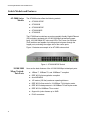


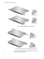


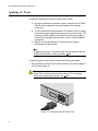

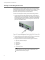


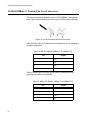


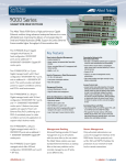


![Installation Guide: AT-TQ2450 [Rev A] (PDF Version)](http://vs1.manualzilla.com/store/data/005654085_1-f326a5d33793ff2ec849a19a13c1dba6-150x150.png)