1
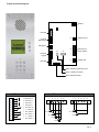
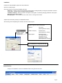
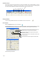
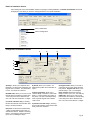
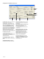
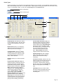
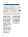
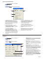
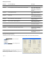
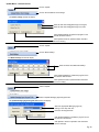
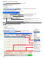
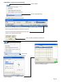
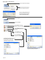
1012
Distributed by Aiphone
INSTALLATION AND OPERATION MANUAL
TABLE OF CONTENTS
TL-2000 Connection diagram
TL-2000 Basic setup instructions for Installer
Installation (starting up program, changing time and date)
Installations screen (existing installation, new installation)
Details of Installation screen (parameters)
Configuration of Installation screen
Relay configuration
Communication Time
Speaker / Microphone Volume
Ring time out
Period Types
Start / Stop time settings for Period Groups
Relay activation rules during Periods
Call activation rules during Periods
Holiday date setting
Screens & Keypad Parameters
Backlight activation time setting
Scroll display speed
Alphanumerical quick-find
Messages
Turn pre-recorded messages on / off
Message volume
Keypad beep activation and volume
Pre-recorded message description
Dialing & Call Progress Detection
Ringing tone settings
Busy tone settings
Sensitivity level – Voice detection
Caretaker
Caretaker details
Managing Agent
Managing agent details
Installation Company
Installing company details
Call-Buttons
Enabling external call-buttons
Sharing Telephone line
RS-485 / Sharing Telephone line settings
Residents and Access
Tel+Access
Creating a resident with telephone and access
Access Only
Creating a resident with access only
Services
Call Log
Screens
How to change and create a custom screen
Audio Messages
How to change and create a custom audio message
Software
Loading
Data transfer
Pg. 2
4
5
6
7
8
9
9
9
10
10
11
11
12
12
12
12
12
12
13
13
13
13
14
15
15
16
16
17
19
19
20
20
20
21
21
Uploading to Panel
Downloading to PC
General info
General information
Keypad Codes
Comments
Printing
Printing data
Exit
Exit installation
Help
Help with install
Update Menu – General Screen
Clock change – Daylight savings time
Holidays
Managing Agent Keypad Code
Installation Company Keypad Code
Update Installations
Change passcodes
Update time
Options Menu – General Screen
Change Password
Reset Database
Backup Database
Restore Database
Reindex Database
Specifications
Default Parameters
Default Messages
22
22
23
23
23
24
24
25
26
26
26
27
27
28
28
29
29
29
29
29
30
31
31
TL-2000 Connection diagram
Speaker
JP6
Not used
JP5
Arrow &
Bell buttons
JP3
Telephone line
CN3
10
Microphone
JP7
REX inputs &
Relay outputs*
CN2
CN6
CN5
12 button
keypad
JP4
Not used
JP8
1
12VDC input
CN1
JP2
DB9 – RS232 programming input
RJ45 – RS485 connection
Direct call button input**
CN2 connections
JP2 connections for direct call buttons
10 Exit button 2
1
2
3
4
5
6
1
2
3
4
5
6
9 Exit button 2
8 Exit button 1
7 Exit button 1
6 NC (Relay 2)
5 C
(Relay 2)
4 NO (Relay 2)
3 NC (Relay 1)
2 C
Call button 1
Call button 5
Call button 2
Call button 6
(Relay 1)
1 NO (Relay 1)
Call button 3
Call button 4
Pg. 4
TL-2000 Basic set up instructions for Installer
Install program from CD. Refer to page 6.
Run program and choose Supervisor from the start up screen. Default password is “super”.
Refer to page 6.
Select Installation from the general menu, and click on the new icon.
accordingly.
Refer to pages 6-8.
Fill out New Installation screen
Change the Parameters as desired from the Details of Installation window.
Refer to pages 8-16.
Enter Caretaker and or Managing Agent information as desired.
Refer to pages 14-15.
Select Tel+Access from the Residents tab in the Details of Installation window, and click on the new icon.
Fill out the Resident’s Details window as desired. Close window and repeat process until all residents are entered.
Refer to page 17-18.
Click Loading tab from the Details of Installation window. Click Configure button to assign the proper COM port.
Click the Connect Now button to connect with the panel.
Refer to pages 21-22
Click Parameters button to upload the Parameters to the panel. Click Residents button to upload the Residents’
information to the panel.
Refer to pages 21-22
Close program.
Pg. 5
Installation
Install the TL-2000 installation program from the provided CD.
Open the TL-2000 program.
Once open choose one of the three available user types.
Supervisor – Allows for full access of all aspects of the program, including the ability to change the parameters of the size
of the system. Typically used for managing multiple installations.
Installation Company – Allows for access to all aspects of the program, not including changing parameters of the system.
Recommend to be used by installer.
Managing Agent – To be used by end user to add, remove, or change tenant names.
Adjust the time and date by clicking on the Modification button.
After choosing user and adjusting time and date, click OK to enter program.
There are 3 types of users to choose from.
Supervisor:
Full access
(default password = super)
Installation Company:
General access
(default password = install)
Managing Agent:
Restricted access
Can change resident’s
information, but not
parameters of system.
(default password = manage)
Click on Modification to change time and date.
General Screen:
To begin a new installation, click on the Installation button in the general screen menu.
Pg. 6
Installations Screen:
in
st
al
ls
of
#
D
el
et
e
Im
po
rt
Ex
po
rt
op
y
C
O
pe
n
N
ew
At the top of the menu there are icons that allow you to create a new installation, open an existing installation, or copy and
delete existing installations. In addition there are icons that allow you to import and export data from TL-2000 entry panels.
The number of saved installations is indicated in an area between the export icon and the exit icon.
Existing installation:
To open an existing installation double click on the installation, then click on the open icon.
New installation:
While in the Installations window, click on the new icon.
The New Installation window will appear. Fill in the appropriate information. Please note the Serial number is on a white
sticker located on the back of the TL-2000 entrance panel. The Passcode is the last 4 digits of the Serial number.
Check this box to have the program generate a name for the
installation based on the street number and address.
The phone number cannot have spaces, blanks, hyphens,
underscores, or colons.
The serial number is found on a white label on the back of the
TL-2000 entry panel.
The initial passcode is the last 4 digits of the serial number.
Click OK after filling in information.
Pg. 7
Details of Installation Screen:
Upon clicking OK on the new installation window or opening an existing installation, the Details of Installation screen will
be displayed. This allows you access to change parameters of a specific installation.
Click on Parameters
Click on Configuration
Configuration of Installation Screen:
F
G
H
A
B
C
D
E
A) Relay 1, allows you to adjust the time
that Relay 1 is active when released by the
keypad code or resident. The default time
is 5 sec., the maximum is 300 sec.
B) DTMF Code, allows you to enter a code
that will allow the resident to activate relay
1 from their phone when called from the
door. The code can be between 1-4 digits.
C) Comms ends after relay 1, checking
this box will terminate communication after
Relay 1 has been activated.
D) Input 2, can be used to activate Relay
1, Relay 2, illuminate the LCD screen, or
activate the Interlock. Default is activating
Relay 2. Activating the Interlock prevents
input 1 from controlling the relays.
E) Period, allows you to select 1 of 5
different time profiles for the activation of
Input 2.
F) Relay 2 Operation, allows you to
choose if Relay 2 activates in unison with
Relay 1, or when pressing any button on
the panel, or to have it act independently
when a specific keypad code or DTMF
code is used.
H) Keypad Codes, allows you to enter 4
codes that can be active during specified
time periods. Keypad code allows you to
activate Relay 2. (min 1, max 8 digits)
Relay operates determines how long
Relay 2 is active. (min 1 sec, max 300 sec)
DTMF code, allows you to enter a code
that will allow the resident to activate Relay
2 from their phone when called from the
door. The code can be between 1-4 digits.
G) Comms ends after relay 2, checking
this box will terminate communication after
Relay 2 has been activated.
Pg. 8
Configuration of Installation Screen cont.:
O
N
M
I
I) Comms Time, allows you to adjust the
time that a panel can remain in
communication. The call will terminate
after the time has expired. (min 10, max
300 seconds) Keypad Errors sets the
maximum number of times an incorrect
code can be attempted before the entry
panel shuts down. (max 9) Keypad Lockout for, sets the amount of time that the
keypad will be shut down. (min 10, max
300 sec) Once the keypad has been
locked out an error / warning message will
be displayed on the panel.
J) Camera 5VDC / Relay 3, allows you to
activate the CN5 connector. Not
recommended to use, contact Aiphone for
additional information.
K) Loudspeaker Volume, adjusts the
speaker volume heard out at the entrance
panel.
L) Microphone Volume, adjusts the
microphone volume heard at the tenant.
Pg. 9
J
K
L
M) Call to Door Panel, allows for a phone
to call the entrance panel, provided it has
the Passcode.
Panel rings for adjusts the amount of time
that the entrance panel will ring when
called. (min 0, max 45 sec)
A 4 digit Passcode must be used to turn
on this feature.
N) Call from Door Panel, controls the
calls coming from the door panel. Prefix
of Telecoms Provider is used if the
telecom provider has a unique prefix.
Handset rings for sets the time that the
entrance panel will ring a telephone
number. (min 10, max 300 sec.)
O) Clocks Change displays the dates
specified in the Installation screen under
the Update tab in the Summer / Winter
Clock Change menu.
Period Types:
Period Types allow you to change the access parameters based on a time schedule. The TL-2000 has 5 different periods
that can be scheduled, Group A, B, C, D, and Door Panel. A period type is a 7 day week schedule, with 1 time zone, 2 time
zones, or a combination of both. To start, click on Period Types from the Parameters tab.
Click on Parameters
Click on Period Types
A
B
C
H
D
E
F
G
I
A) Group A, B, C, D, allows you to select
up to four different groups, with each group
having its own parameters for door entry
controls.
B) Door Panel, allows you to determine
what occurs at the door panel during the
different periods. (see next page)
C) Keypad Codes, opens a 2nd window
that allows you to enter 4 different codes
for the specified period. When the codes
are entered during the specified period,
Relay 1 will be activated.
D) Name, allows you to name the specific
periods.
E) Calls Inside of Periods 1 and 2, will
determine what the panel does during the
specified periods when the bell button is
pressed after locating a tenant. Calls will
allow the panel to call a tenant. Activates
Relay 1 will activate relay 1 instead of
calling the tenant. Activates Relay 2 will
activate relay 2 instead of calling the
tenant. Activates Relays 1 and 2 will
activate relays 1 and 2. Activates
Relay(s) of Resident will activate the relay
associated with the tenant. Security
Delay triggers the associated relay after a
specified timeframe to give the impression
that the entrance was monitored before
giving access to building. (max 60 sec)
F) Call Outside of Periods 1 and 2, will
determine what the panel does outside of
the specified period. Calls will allow the
panel to call the tenant. Plays Message 2
will play pre-recorded message 2 rather
than call the tenant. The default message
2 is “Your correspondent cannot be
reached at this time, please try again
later”. Calls Caretaker calls the preassigned number rather than the tenant.
G) Bank Holidays will refer to isolated
dates that should ignore the specified
periods. Enter the month and day
numerically.
H, Period 1, Period 2. Enter the hour and
minute for each day for the start and end of
the specified period. Put time in the 24
hour format. If all times are the same as
Monday, simply click on the Copy Monday
button to auto-populate the remaining
days.
I) Holidays, allows you to enter a start
date and end date if sequential days need
to ignore the specified periods. Enter as
month/day/year.
Pg. 10
Period Types (continued):
Select the Door Panel tab.
J
K
L
J) Operation Mode, allows you to choose
between the different modes available.
Active Periods are the times between
Open and Close during Period 1 and
Period 2. When Active Periods is selected,
“Free Access” will be displayed on the
panel along with an arrow pointing toward
the bell button. During this time the door
will be released when the bell button is
pushed. When Controlled Access –
24hrs is selected, the door will not be
released unless the proper key code has
been used or the tenant releases the door.
When Free Access-24hrs is selected,
“Free Access” will be displayed on the
panel along with an arrow pointing toward
the bell button. During this time the door
will be released when the bell button is
pushed. If the arrows are used to scroll to
a name and the bell button is pushed, the
tenant will be called.
K) Relay 1 Latched (Door “Hold Open”),
when selected, Relay 1 contacts are kept
latched for the duration of the specified
period. Relay 2 Latched (Door “Hold
Open”), when selected, Relay 2 contacts
are kept latched for the duration of the
specified period. When Free Access and
Door “Hold Open” are selected, the display
will say “Free Access” with the arrow
pointing toward the bell button. However,
pressing the bell button will not be
necessary as the contacts will remain
activated for the specified period.
Pg. 11
L) Scroll Display of Residents, allows
you to choose between displaying or not
displaying the resident’s information during
the specified period when Free Access is
displayed on the panel. Selecting Off will
prevent the entrance panel from scrolling
to a tenant’s name during the specified
period. Selecting Information and
Activation of Resident’s relay will allow
the entrance panel to scroll to the tenant’s
name. Pressing the bell button will activate
the associated relay, but will not call the
tenant. Selecting Fully Functional,
Information + Call will allow the bell
button to activate the associated relay, as
well as allowing the entrance panel to
scroll to a name and call the tenant.
Screens & Keypad Parameters:
Click on Parameters
Click on Screens & Keypad
A
D
B
C
A) Backlight Activation, brightens the
display screen between the start and end
times set. When installed in a bright area,
you may want to adjust the time so that it is
off during daylight hours.
B) Scroll Display Speed, adjusts the
scrolling speed when using the arrow keys
to scroll through the names.
C) Checking the Resident
alphanumerical quick-find box, allows
the number buttons to be used to “jump”
alphabetically. 2=A, 3=D, 4=G, 5=J, 6=M,
7=P, 8=T, 9=W. Enabling this requires that
the “#” key is entered prior to any keypad
entry code.
Checking the Speed dialing box enables
the speed dial feature, allowing visitors to
dial tenants by either their apartment
number or personal number.
Checking the Direct dialing via* box
allows a visitor to dial a tenant by pressing
the * followed by the tenant’s phone
number.
D) Screen Resets allows you to adjust the
time before the screen resets back to the
default screen. (min 2, max 10 sec)
Messages:
Click on Parameters
A) Message 1-9, are voice announcements heard
at the door panel. Checking the On box will allow
that message to be accessed.
Click on Messages
B) Message 4, corresponds to the activation of
Relay 1 and 2. It can either be a voice message, a
single beep, or a beep for the duration of the relay
contact.
A
B
C
D
C) Message 10 has 3 options: Off, On, and
Response Off. On allows the message “Call from
Door Panel” to be heard at the phone receiving the
call and at the panel. Response Off only plays the
message at the phone, not at the panel.
D) Message Volume on Speaker controls the
volume heard at the panel. Beep Volume controls
the volume of any beeps heard at the panel.
Message Volume on Line controls the volume
heard by the phone. Checking the Keypad Button
Beeps box allows the panel to emit a beep every
time a button is pressed.
Pg. 12
Messages (Continued):
Message #
Pre-recorded Message
Event Type
Message 1:
“Please wait, your call is in progress”
Each time a call is made.
Message 2:
“Your correspondent cannot be reached at this time. Please try again.”
When a visitor presses the bell
button to call a resident outside of
Periods 1 & 2. i.e. Off hours or
when residents do not want to be
disturbed.
Message 3:
“You have dialed incorrectly.”
When a visitor has entered an
incorrect telephone number on the
panel.
Message 4:
“Please enter.”
A correct keypad code has been
entered, or the resident has activated
the door release from their phone.
Message 5:
“Sorry, the line is busy. Please try again later.”
When the resident’s telephone line is
engaged or occupied.
Message 6:
“Sorry, no answer. Please try again later.”
When there is no answer from the
resident’s telephone number.
Message 7:
“The code entered is incorrect.”
When an incorrect keypad code has
been entered on the panel.
Message 8:
“Sorry your call cannot be made, please try again later.”
Spare
Message 9:
“Please dial your correspondent’s telephone number.”
Resident’s status is protected,
requiring visitor to enter resident’s
telephone number.
Message 10:
“Call from door panel.”
Message heard at resident’s phone
when receiving a call from the
entrance panel.
Dialing & Call Progress Detection :
The Dialing & Tones menu should not have to be accessed unless tying into a PABX or other setup with differing parameters.
Click on Parameters
Click on Dialing & Tones
Audible call progression, when selected, allows the panel to hear
the progression of a call they make to a tenant.
Manual call progress detection is used for testing purposes only.
Pg. 13
Caretaker:
Click on Parameters
Click on Caretaker
Enter the Caretaker information if applicable. If
Caretaker needs to be accessed by the entry panel,
check the “Is a Resident” box.
When the “Is a Resident” box is checked, the
Caretaker Details window will open. If you need to
make changes to this information after you close
the window, open it through the Residents tab.
Checking the Hidden box will hide all aspects of
the Caretaker from the panel.
Checking the Protected box will require a phone
number before a call from the entrance panel will
go through.
Pg. 14
Managing Agent:
Click on Parameters
Click on Managing Agent
Click on the Add Managing Agt.
button to open a new window that
will allow you to enter in the
Managing Agent’s information.
Click on the Persons button to
open a new window that will allow
you to enter in contacts for the
managing agent.
Clicking on the New button in the
contact window will open the
Person Details window, allowing
you to add a contact to Managing
Agent.
Installation Company:
Click on Parameters
Click on Installation Company
Pg. 15
Follow the same process that you used for adding a
managing agent and managing agent contacts to add an
Installation Company.
Call-Buttons:
Click on Parameters
Click on Call-Buttons
Up to 6 call buttons can be added to the entry panel for quick reference. Check the boxes for the appropriate
call buttons you will be adding to JP2 (refer to pg.3)
Press Duration is
the time the button
must be pressed
before the panel
launches the call.
64 buttons option is
not available in North
America.
Sharing Telephone Lines:
Click on Parameters
Click on RS485 Network
Select how many panels will be sharing the telephone
line and set the priority level for each panel. Use the
priority drop down box to select the priority level for each
of the other panels when logged into each respective
panel.
A maximum of 5 TL-2000 panels can be connected
together via an RS485 bus. Connect to CN5 on PCB.
Do not check the Network On for Modules box.
This is used when integrating the panel with other access
modules. This is not a supported feature at this time.
Pg. 16
Residents and Access:
O
pe
n
N
ew
re
s
id
en
t
Click on Tel+Access
re
si
de
nt
D
el
et
e
re
si
de
Im
nt
po
rt
re
si
de
nt
U
ni
ve
rs
al
Ac
ce
#
ss
of
C
re
od
si
e
de
nt
s
Click on Residents
Click on New to add a Resident
The Resident’s Details screen will display. Enter the relevant
information and click OK when finished.
Check Hidden if you wish no details
regarding this resident to be displayed on the
door panel. If hidden, visitors will need to
know that the resident lives in the building
and will enter * followed by their telephone
number to call the resident.
Check Protected if you wish to prevent the
visitor from calling the Resident by pressing
the bell button. The panel will play a
message directing the visitor to dial the
resident’s telephone number. Enabling this
will prevent residents from being
unnecessarily disturbed by strangers or from
receiving nuisance calls from people
“playing” with the panel.
Note: When protected, if the telephone
number physically dialed is busy or there is
no answer, the system will not automatically
dial the 2nd telephone number.
Use to assign resident to a dedicated call
button on the panel, if applicable.
Use to associate the resident with a period
type. Example: to be protected from
nuisance calls during early morning hours.
Enable/Disable the relay rights for Relay 1
and Relay 2.
Pg. 17
Use to assign the resident a keypad entry
code. This code can be time period
controlled using Access period.
Residents and Access (Continued):
The residents and all of their
details will be displayed on this
screen. Use the scroll bar to
move through the listing. You
can list the residents
alphabetically by clicking on
Correspondent name.
The Caretaker information
entered previously will be
displayed on this screen if “Is a
Resident” was checked during
setup.
You can assign a universal
access code for all residents.
Click the Universal Keypad
Code icon. A new window will
open and you can enter your
desired code here. This
keypad code will be valid at all
times until changed or deleted.
Each resident can have a
personal keypad code which
can either be valid at all times
or be Group/Period controlled.
Prot. Will show a check in the box
if you set the resident to be
protected in the Resident Details.
Hide will show a check in the
box if you set the resident to be
Hidden in the Resident Details.
Note: The Protect and Hide check boxes cannot be edited from this page. You must select the resident in question and select the
edit icon. This will open the Resident’s Details page and you can make your changes there.
Pg. 18
Access Only:
Click on New to add a Resident
Click on Residents
The Resident’s Details screen will display. Enter
the relevant information and click OK when finished.
N
ew
re
si
de
nt
O
pe
n
re
si
de
nt
D
el
et
e
re
si
de
nt
U
ni
ve
rs
al
Ac
ce
#
ss
of
C
re
od
si
e
de
nt
s
Click on Access only
Access Only is used to provide access into the building
via a keypad code. A unique code can be set up for
persons that may require access to the building. You
can restrict usage of the code using Period types.
Services:
The Important Services – Contact Details
screen will display. Enter the relevant
information and click OK when finished.
Click on Residents
N
ew
se
rv
O
ic
pe
e
n
se
rv
D
ic
el
e
et
e
se
rv
U
ni
ic
e
ve
rs
al
#
of
A
se cce
rv
ss
ic
C
es
o
de
Click on Services
Click on New to add a Service
Up to 10 Services can be programmed to the
entry panel. All of the programming and
functions of the Services section and sub
screens are the same as the Residents section.
Pg. 19
Call Log:
Click on Residents
The Call Log screen displays the quality
and duration of calls made to each resident
in the building.
Click on Call Log
You have the choice
of saving the Call Log
data in Excel or Word
formats.
Screens:
Click on Screens
The standard Defaut.ecr screen is
the default and should be used.
Click Help if you want information
on how to create customized
screen files.
If you have customized a screen for a
particular installation and saved it under a
different file name, use the drop down box to
see a list of screen files available and select
accordingly. Click OK when finished. You
will need to upload the customized screen
file to the panel for it to take effect.
Audio Messages:
Click on Messages
US_V3.son is the default audio
message file.
Click Help if you want information
on how to create customized audio
message files.
To select a different audio
message, use the drop down box to
see a list of audio messages
available and select accordingly.
Click OK when finished.
Pg. 20
Software:
Click on Software
The Program in the panel box details the
version of software that is being used and
allows you to select different versions to use.
This is used to update installations with the
latest software releases.
Loading:
All programming changes made using the TL-2000 application software must be uploaded from the PC to the panel to take effect.
Click on Loading
The Data Transfer screen opens.
Click on Configure
Current Status
The Connection Parameters screen opens.
Connection to the TL-2000 panel can be made in two ways:
1. From a COM (Serial) Port of a Laptop or PC to connector CN6 on the PCB of the panel using a DB9 (null modem) serial cable.
2. Remotely from a PC via an analog modem (max speed 33,600 bps) via the phone line.
Select the COM port if connecting locally.
Select which modem to use if connecting via the phone line.
Click OK when done. The Data Transfer
window will display again.
A new Data Transfer screen will display
showing the status as “ON LINE”.
Click on
Connect Now
Pg. 21
Uploading / Updating Panel:
The programming information must be sent (uploaded) to the Panel to take effect.
Click on Parameters to upload all settings and
configurations programmed in all of the
Parameter sub-menus and sections.
Click OK.
Follow the same procedure when uploading the
Residents, Screens, Messages, and Program.
Each section must be uploaded separately.
A successful transmission
message will appear.
When updating an existing installation, it is
recommended to download the data from the panel,
make your necessary changes, then upload those
changes. This will ensure that you do not accidently
overwrite any required data.
Downloading / Updating PC:
Click on Parameters to import the parameters
currently stored in the panel to your PC.
Pg. 22
General Information:
Click on Installation
Click on General
The Installation window will display.
This screen will display all of the general
installation information for the particular
job / installation you are logged into.
Keypad codes:
Click on Installation
Click on Keypad codes
The Keypad code list window will display.
This is a list of all of the keypad codes
that are programmed for this specific
job / installation.
Comments:
Click on Installation
Click on Comments
This will direct you to your Word program. This is used to make notes / comments for the installation. The Word document will be
defaulted to save as the name of the installation.
Pg. 23
Printing:
Click on Print
The Printing window will display
Select Preview to preview the document and
choose the program you would like to save the
file to (Word, Excel, HTML, PDF).
Select Print to have the document sent directly to
your printer for a hard copy.
Select the format in which you would like
to save/export the document.
Exit:
To exit an installation:
To close the program:
Click on Exit
Click on Exit
Click on Exit installation
Click on Close program
Pg. 24
Help:
Click on the Question Mark (?)
This will open an HTMP Help window. You can use this help window for assistance on how to program the different
features of the TL-2000 panel.
Pg. 25
Update Menu – General Screen:
Click on Update
Click on Summer/Winter Clock Change
The Clocks Change window will display.
Enter the date when Daylight Savings Time begins.
Enter the date when Daylight Savings Time ends.
Click Update Database to update the program on the
PC with the dates entered.
Click Upload to Panel to upload the dates entered to
the Door Panel(s).
Click on Update
Click on Bank Holidays
The Bank Holidays window will display.
Enter the dates of the National Holidays.
Click Update Database to update the program on the
PC with the dates entered.
Click Upload to Panel to upload the dates entered to
the Door Panel(s).
Click on Update
Click on Update Managing Agent Keypad Code
The Update Managing Agent Keypad Code window will display.
Select the appropriate Managing Agent by
clicking on the drop down box.
Enter the new Keypad Code.
Click Update Database to update the program on the
PC with the code entered.
Click Upload to Panel to upload the code entered to
the Door Panel(s).
Pg. 26
Update Menu – General Screen (Continued):
Click on Update
Click on Update Installation Company Keypad Code
The Update Installation Company Keypad Code window will display.
Select the appropriate Installation Company
by clicking on the drop down box.
Enter the new Keypad Code.
Click Update Database to update the program on the
PC with the code entered.
Click Upload to Panel to upload the code entered to
the Door Panel(s).
Click on Update
Click on Update Installations
Choose how to sort
the installations.
The Updating of Installations window will display.
Select the installation
you wish to update.
The selected installation
will appear here.
Select what you want to
update to the selected
installation(s).
Choose your connection.
Select Configure to
change the Com Port.
Click Loading to update
the selected installations
with the types chosen.
Pg. 27
Update Menu – General Screen (Continued):
Click on Update
Click on Change Passcodes
The Update of Passcode window will display.
Select the appropriate installation as explained on page 25.
Click on the relevant cell in the New Passcode column and
ender the new 4 digit Passcode number.
Click on Loading to upload the new passcode.
Click on Update
Click on Clock
Your PC Date and Time Properties window will display.
Select the installation(s) you wish to set the time on
and click on Loading to update.
Set the time and click ok. The Update of Clock
window will display.
Pg. 28
Options Menu – General Screen:
Click on Options then Password
Click on the level for which you
wish to change the password.
The Change Password screen will display
Enter the existing password for the
level you have chosen, then type
the new password and retype it to
confirm. Press OK when done.
Click on Options
Click on Database
Click on Reset to restore the
database to factory set defaults.
Click on Backup to save the
programmed information and data
to your PC.
Click on Restore to restore
from an earlier backup.
Click on Reindexing to
reorganize the database.
The Reindexing function reorganizes the
files into their correct order. It is
recommended to use this feature
periodically if changes are made.
It is recommended to regularly back up all
programmed information and data.
Pg. 29
Specifications:
Connections
Operator Analog Line (a/b) or PABX extension of the internal telecommunications
network of company.
Socket to be analog type.
Telephones
1)
2)
3)
Standard analog DTMF “Touch Tone”
Mobile telephone
Cordless phone
Note: Pulse tone compatible.
REN Loading
=1
Maximum REN on any PSTN line = 4
If any 3rd party equipment is connected in parallel, for example:
burglar alarm, socket, etc. REN loading must not be exceeded.
Power Supply
12V DC Regulated
Power Consumption
450mA at 12VDC
CE Norms:
EN60950
EN55022 Edition 98 Class B
EN55024 Edition 98 Class B
Telecommunications Norms:
CTR21
Operating Temperature
5ºF to 140ºF (-15ºC to +60ºC) Non-condensing
Number of Relays
2 (+ 5V DC output, adjustable 1-300 secs)
Relay Timers
Relay 1 = 1-300 secs
Relay 2 = 1-300 secs
Relay with ON/OFF period controlled latch mode possibility
Relay Contact Ratings
Relay 1 = 2 Amps at 12V DC / 1 Amp at 24V DC
Relay 2 = 2 Amps at 12V DC / 1 Amp at 24V DC
Request to Exit
2 (N/O contacts)
Programming
PC running Windows 98, ME 2000, XP, Vista, or Windows 7. TL-2000
software is available on CD-ROM.
1) From COM Port of a Laptop or PC to connector CN6 on the back of unit
(RS232 bus, 38,400 bps).
2) Remotely from a PC via an analog modem (max. speed 33,600 bps) via
the PSTN or internal PABX.
System Capacity
2000 main telephone numbers or extensions + 2000 2nd telephone numbers.
Keypad Entry Codes
1 no. per resident = 2000
Trades via Keypad code
4 codes – Group A (Time Profile A)
4 codes – Group B (Time Profile B)
4 codes – Group C (Time Profile C)
4 codes – Group D (Time Profile D)
Keypad code length
3-8 digits, any combination
Trades – button
Yes (Time Profile = Door Panel)
Key override
Via REX inputs. Override device not provided by Aiphone.
Non-volatile memory
Yes
Time, Day, Date, Calendar
Yes
Material
BS316 grade stainless steel.
Dimensions
H 13-3/8" x W 6-1/8" x D 1-¾”
Default Parameters
Relay No. 1 activated by:
Telephone handset code
Operation time (sec)
0
5
Relay No. 2 activated by:
Telephone handset code
Keypad on panel code
2
4444
Operational time (sec)
5
Operational mode
Controlled access – 24 hrs
Managing Agent keypad code
Off
Installation Company keypad code
Off
Communication time (sec)
60
Handset rings for (sec)
25
Panel rings for (sec)
6
Incorrect keypad entries prior to lockout
Unlimited
Keypad lockout for
Off
Door “Free Access” times
Off
Audio messages
On
Ring tones
OP settings
Busy tones
OP settings
Default Messages
Message 1:
“Please wait, your call is in progress”
Message 2:
“Your correspondent cannot be reached at this time. Please try again.”
Message 3:
“You have dialed incorrectly.”
Message 4:
“Please enter.”
Message 5:
“Sorry, the line is busy. Please try again later.”
Message 6:
“Sorry, no answer. Please try again later.”
Message 7:
“The code entered is incorrect.”
Message 8:
“The code entered is correct.”
Message 9:
“Please dial your correspondent’s telephone number.”
Message 10:
“Call from door panel.”
Message 1-9 must be in the format wav, A-law, mono, 8000Hz. Message 10 must be in wav, linear 8 bits, mono, 8000Hz.
http://www.aiphone.com/
AIPHONE CO., LTD, NAGOYA, JAPAN
AIPHONE CORPORATION, BELLEVUE, WA, USA
AIPHONE S.A.S., LISSES-EVRY, FRANCE