1
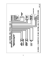
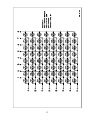
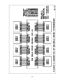
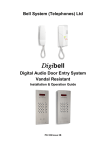
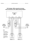
Bell System (Telephones) Ltd.
BSX
DOOR ENTRY TELEPHONE EXCHANGE
Installation
and
Operation
Issue 3.00
PLEASE READ THIS MANUAL PRIOR TO INSTALLATION. IF YOU ARE NOT SURE ON
ANY INSTRUCTION PLEASE CONTACT YOUR DISTRIBUTOR FOR FURTHER
GUIDANCE
CONTENTS
1.
2.
3.
Introduction
...................... 1
Control Unit BSX
...................... 1
The Entrance Panel
...................... 2
Model 51 Speech unit
...................... 2
Telephones
...................... 2
Installation Procedure
...................... 3
Cable Requirements
...................... 3
Connections to panel
...................... 5
Electric Lock Release
...................... 5
Tone Output
...................... 5
Fire Service Switch
...................... 5
Door Monitoring
...................... 6
Dual Entrance model
...................... 6
Testing & Troubleshooting
...................... 7
Installing the battery
...................... 8
Technical Help
...................... 9
Time Clock operation
......................10
Diagrams
1.
2.
3.
Connections to Entrance Area
CTX816
Connections to Panel Push-buttons CTX816
Connections to Telephones
RLX816
...................... 14
...................... 15
...................... 16
4.
5.
6.
Connections to Entrance Area
CTX864
Connections to Panel Push-buttons CTX864
Connections to Telephones
RLX864
...................... 17
...................... 18
...................... 19
Introduction
The BSX Door Entry Telephone System is designed for low rise blocks of flats. It provides the
means for visitors to call an individual resident within the building and to establish two-way
speech communication (full duplex) with them. The resident is allowed full control over the
callers' access to the main entrance by means of an electric lock release or an electric lock.
The BSX includes a sophisticated microprocessor-based Control Unit which operates on the
'Telephone Exchange' principle. This approach has two main advantages over common-wired
entry phone systems ;
C
Conversations are totally private.
C
Any damage sustained to an individual telephone or its associated cable will not affect
the operation of the rest of the system .
Various models of front door pane and telephones may be used with the BSX equipment.
The Control Unit
The BSX Control unit is available in multiples of 8 up to 56 stations, and then a 63 station
control. (The DAX digital system is available for systems up to 256 stations). Multi entrance
systems are available with an additional CTX Control board for each entrance.
C
A CTX816 control board is used for systems up to 16 stations ( except when door
monitoring telephones are used).
*
A CTX864 control board is used for any other system, or for any system using
telephones with door monitoring.
All the control equipment is installed in a lockable steel cabinet and mounted onto a subchassis which can easily be removed from the cabinet to allow the installer to cut holes for
cable/conduit entry. The Control unit includes the following;
Model PSU138A or PSU138B Power Supply
Model CTX Door Controller
Model RLX Relay boards
Model TS2000 quartz reserve time-clock
A 12v 6A/H battery when standby is required (Optional)
Connections to each telephone are protected with relays and fuses and have a diagnostic led
indication .
Provision has been made for either Fail-Secure or Fail-Safe electric lock releases or electric
locks to be used. The time duration of door release operation is programmable .
1
The Entrance Panel
This is commonly a model VRP or LCP series panel, being a flush mounting stainless steel
(BS316) vandal-resistant panel. The panel is fixed by tamper-proof bolts and is to be located
on the wall adjacent to the main entrance of the dwellings. The panel can be supplied in a
variety of sizes and with custom engraving details. A single flush type vandal resistant
button is provided for each flat and one for the timed entry of Services. A grill is also engraved
into the panel which conceals the Speech unit.
Model 51 Speech Unit
The Model 51 Speech unit is recommended for use with the BSX system. It provides fullduplex speech between the front door and the telephone. It has a weather-resistant
plastic-cone loudspeaker for speech-out, and a dynamic, low frequency microphone for
speech-in. Both amplifier circuits (in and out) use a custom designed Hybrid circuit for high
reliability. The volume of each amplifier can be individually adjusted with two continuously
variable controls.
Telephones
The following telephone models are compatible with the BSX control ; 500D, 500X, 500XT,
500LX, and 500LXT.
Although the control unit will work with a variety of telephones the model 500X has been
designed specifically to take advantages of its facilities. The model 500LX telephone is
available for door monitoring having a second led to indicate when the door is open ( this
telephone requires 7 wires and must be installed with the CTX864 control ).
The model 500X telephone is completely manufactured in the UK for use in Public Housing
and specifically for the BSX system. The body is made of high impact ABS plastic, with a total
plastic moulding weight per handset being approximately 275 g. The handset cord is coiled and
has a sleeve at point of entry to the handset for longevity of life .
When called the resident needs only to pick up the handset to speak with the caller. The
speech circuitry is of high quality and includes the facility for the installation of an inductive
device to operate a hearing aid (switched to 'T') .
The telephone has a DC buzzer which is operated by an associated push button at the entrance
panel.The facility for extension bells, tones, and relays for switching lights etc. has been
included .
Residents may mute the buzzer by operating a button on the telephone; a red LED light
illuminates to remind them that the telephone is muted . Depressing the same button will
reconnect the buzzer and the red LED light will no longer be illuminated. Clear instructions
are provided on the cover. A second button on the telephone may be used to operate an
electric door release only after being called.
2
Installation Procedure
Fitting the Control Unit
All of the equipment within the control unit box is mounted on a removable plate. It is important
that while the box is being drilled for cable-entry conduits and being secured to the wall that the
equipment is removed to prevent metal swarf from falling onto PCBs.
Cable Requirements
Use 0.5mm solid-core twisted-pair telephone cable (BT specification CW1308, or equivalent)
for all telephone and door panel connections; this is essential for correct operation of the
system and for compliance with European EMC Directive 89/336/EEC. Avoid running any cables
alongside mains or other data transmission wiring.
Connections to each Door Controller
(CTX PCB)
Cores
Diameter
Max.Length
Speech Unit (Door panel)
5
0.5mm
50m
Lock release
(0.5A rating)
2
0.5mm
1.0mm
25m
100m
Exit / Fireman’s Switch or Door Open Switch
2
0.5mm
100m
Tone Output/Sounder
2
0.5mm
100m
Engage Lamp
2
0.5mm
100m
Connections to Push-buttons
-
as per diagrams
Connections to Telephones (full isolation)
500D Telephone
5
0.5mm
100m*
500X Telephone
6
0.5mm
100m*
500LX/500LXT Telephone
7
0.5mm
100m*
These restrictions are unlikely to be exceeded in most circumstances; if they present a problem
please contact the Manufacturer for further advice.
3
Model PSU138 Power Supply
Important Safety Information
The Model PSU138 Power Supply must be mounted in a ventilated cabinet/enclosure designed
to house 240V AC mains electrical equipment.
The cabinet must be in a protected indoor environment, close to a 240V electrical supply, e.g.
an electrical cupboard. Connections to the 240V AC mains supply must be carried out by a
qualified electrician or similar competent person, and made in accordance with accepted safety
practices. A good mains safety earth must be connected to cabinet and Power Supply. A twopole switch (as provided by a Consumer Unit or Switch-Fuse) must be included to isolate both
Live and Neutral during Installation or Maintenance. The circuit must be protected by a current
limiting fuse or other device with a maximum rating of 5A.
The transformer is protected by a fuse; always replace this with the correct type and rating:
T315mA 250V
(20mm glass fuse, 315mA, 250V, Time delay, approved to
BS EN 60127 or equivalent.)
Mains Cables
Use only mains cable to BS6004, BS6500, or equivalent, within the following specified limits:
Minimum
Maximum
Conductor Diameter
1.0mm (0.75mm2)
2.25mm (4mm2)
Cable Diameter
4.0mm
8.0mm
When fitting the cables (both primary and secondary) only feed them through the blind
grommets provided, first cutting a slit in each. Do not remove the grommets or make any other
holes.
Battery
The enclosing cabinet must be vented to avoid the build-up of gases. Do not block any vents
which maybe apparent. Care must be taken to ensure the battery terminals are not shorted
together by metal objects as this may constitute a Fire Hazard. Observe the correct polarity
when connecting:
Red wire
Black wire
-
Positive
Negative
The Battery is protected by a fuse, always replace this with the correct type and rating:
F3.15A 250V
(20mm glass fuse, 3.15A, Fast Blow, approved to BS EN
60127 or equivalent.)
4
Connections to the Entrance Panel
All connections to the entrance panel and doors are provided by the control PCB marked 'CTX';
if the unit is a two door system then there will be 2 of these boards, one for each entrance.
Up to 16 push-buttons are wired to the control CTX816 PCB as shown on Diagram 2. It is
unnecessary to run a pair of connections for each push-button; by using a system of '2 out of
8 combinations' the number of connections is reduced to a maximum of 8. Up to 63 pushbuttons are wired to the PCB CTX864 as shown on Diagram 5.
The Service button is wired as a separate pair of connections to the terminals marked 'SERV',
or via the time clock as in Diagram 1 depending upon the Control used.
Electric Door Release
The Control PCB provides 2 alternative pairs of outputs for electric lock releases;
'FAIL SECR': Use these connections for 'FAIL-SECURE' lock releases. These devices require
power to release the door and therefore will secure the door in the event of power failure.
'FAIL SAFE': Use these connections for 'FAIL-SAFE' lock releases and magnetic locks.Both of
these devices require continuous power to lock the door and thus will release the door if power
fails.
Both outputs are specified at 12v DC with a maximum current consumption of 0.5A. For electric
lock releases of other types or specifications please contact the manufacturer for information
on interface adaptors.
Tone Output
This output may be connected to a DC SOUNDER placed in the entrance panel or close by.
The output becomes active during the operation of a push-button to re-assure the visitor that
the resident is being called, and also while the electric door release is being operated to signal
the visitor to enter.
The specifications of this output is 12V DC @ 100mA max.
Fire Services Switch
A pair of connections marked 'FIRE' on each control PCB can be connected to a remote
keyswitch for use by the Fire Services. The key-switch must have a single, isolated, normallyopen contact. Operating this switch will have the effect of permanently releasing the door.
If this facility is to be used the electric lock release employed must be of the continuously-rated
type.
5
Connections to the Telephones
The telephone connections are provided by the RELAY PCB in the control unit marked 'RLX'.
Each relay board has provision for 8 telephones , hence a 16-way system has two of these
boards and a 40-way system has five.
There are 6 connections to each 500X telephone and 7 connections for 500LX telephone;
a separate cable should be used for each telephone.
Dual Entrance Models
These models contain two control PCBs ( CTX ) each of which is connected to either entrance
exactly as shown in diagram 1 or diagram 4. The operation of the BSX from each entrance is
the same as for a single entrance model except it should be verified that the operation from one
entrance will inhibit operation from the other. However, an engaged lamp output is available on
the CTX864 board only.
Door Monitoring
For door monitoring the model 500LX telephone should be used. These telephones are to be
connected to the RLX864 boards with 7 wires. The control CTX864 has a terminal marked
'DOOR SW ' and this must be wired to a normally open door contact.
For door monitoring please ensure that you are using a control that includes the CTX864
and RLX864 boards (there is no provision for this facility on the CTX816 board)
6
Testing & Troubleshooting
Push-button Operation
Apply mains power to the control unit and turn on at the fused isolator switch.
When a push-button is pressed the associated speech-circuit on the relay board (RLX) should
engaged for 60 secs then drop-out. Each circuit on the relay board has an led indicator
adjacent to the telephone terminal block. Test each button on the entrance panel in turn
confirming that the associated LED only comes on, and wait each time for it to clear.
In the event of problems it can be verified that the equipment is operating correctly by
temporarily disconnecting the push button connections and all other external
connections then use a short length of wire to simulate each button according to the matrix
shown in diagram 2 or diagram 5 (eg to simulate button 1, momentarily short 'A' to '1').
Assuming that the equipment is functioning correctly any problems must be traced to the pushbuttons and/or their associated wiring.
Testing the Telephones
Having established that each entrance button is correctly engaging its associated speech circuit
on the relay board(s), it is now necessary to test each telephone in turn:
1.
First check the operation of the mute facility by pressing the 'PRIVACY' button on the
telephone and observing that the red LED alternatively lights and extinguishes. If the
LED does not light then check the telephone cabling (in particular lines V & O, V is +12
V DC and O is negative). Check also the associated fuse on the relay board; this fuse
will only blow if there is a short-circuit on the cable; under no circumstances replace this
fuse with an incorrect type or rating (it is 200mA, 20mm, Quick Blow). When the mute
circuit is operating leave it in the OFF state (ie LED off).
2.
Call the telephone being tested by pushing the appropriate button on the entrance
panel; it should sound loud and clear. If there is no buzzer operation verify again the
relay board LED and fuse and then check the 'I' connection to the phone for possible
faults.
3.
Once the telephone has been successfully called it should be possible to converse with
the entrance. If there is no speech available in either or both directions check firstly the
speech unit volume controls and secondly the cable connections;
The Model 51 Speech Unit has 2 volume controls:VOL A: controls the speech level from phone to panel.
VOL B: controls the speech level from panel to phone.
Initially set both controls to mid-position and adjust each in turn for optimum speech
clarity. It should be noted that if either or both controls are turned too high there will be
a howling sound caused by acoustic feedback. This problem may also be induced by
7
allowing a space between the speech unit and the inside surface of the panel (ie grill).
The connections affecting the speech operation are CHROT to the speech unit and R
O T to the phone; R carries speech from phone to panel and T from panel to phone with
O being the common negative; C & H carry power to the speech unit where C is
+12VDC and H is -12VDC ( H & O are connected together internally within the speech
unit).
To simplify testing the speech of either telephone or speech unit ensure 12VDC is correct
at C (+) & H (-), then temporarily connect R O T of the speech unit to R O T of the
telephone with a short length of cable.
4.
While the telephone is active for speech the Lock button on the phone (lower) should
now be pressed; this should trigger the operation of the lock release for approx. 3
secs (or another specified time) and then immediately disconnect the call (LED on
relay board goes out).
Lock Release Outputs
If the lock release cannot be made to operate then the output from the control PCB should be
verified with a voltmeter whilst disconnected. Assuming the output is correct, check the cables
as well as determining that the lock release is of the correct specification and connected to the
correct failsafe or failsecure terminals.
Installing the Battery
The battery (if required) should be installed only after all tests on the system have been
completed and any faults have been cleared. Take care not to inadvertently short out the
battery terminals as the available current (200A) may burn or overheat cables and other metal
objects. Once installed the battery is safe and fuse-protected. The battery sits on the base of
the control cabinet and is connected to the free spade connections already provided. Ensure
the correct polarity is observed; the red wire with the red spade terminal goes to the battery
positive terminal (also red).
NOTE: The battery will be shipped in a partial state of charge and may require charging
for several hours before use.
Now test the system again with any telephone, firstly with the mains on and secondly with it
off. If the system fails to operate satisfactorily when the mains has been failed then check the
fuses and also the battery voltage (should be 13.8V +/-0.25V). If the battery voltage is
low then allow several hours for it to charge with mains power present and test again.
DO NOT allow the system to operate for a protracted period on battery only (ie mains
switched off) or the battery may be irreversibly damaged by deep discharge.
8
Technical Help
If you are experiencing any problems or have any questions regarding the installation please
contact the Manufacturers:-
Head Office
Bell System (Telephones) Ltd
Presley Way
Crownhill
Milton Keynes
MK8 0ET
Tel: 01908 261106 Fax: 01908 261116
email: [email protected]
9
The TS2000 Time-Clock Module
This section describes the operation and programming of the TS2000 Time Clock module for
use with the Tradesman’s facility.
CAUTION
The unit is intended for 12V AC / DC operation only, and must not be connected to the Mains
supply or used to switch Mains voltages.
Operation
N.B.
Before programming or setting the clock for the 1st time press the RESET button.
10
To set the current TIME and DAY:
1.
Hold
and press
until the correct day is displayed.
2.
Hold
and press
until the correct hour is displayed.
3.
Hold
and press
until the correct minutes are displayed.
To set the programs:
1.
Press
once, 1on will appear. This displays the switch on time
of the 1st program.
2.
Press
to select the program period. There are 15 settings:
Mo+Tu+We+Th+Fr+Sa+Su
Mo, Tu, We, Th, Fr, Sa, or Su
Mo+Tu+We+Th+Fr
Sa+Su
Mo+Tu+We+Th+Fr+Sa
Mo+We+Fr
Tu+Th+Sa
Mo+Tu+We
Th+Fr+Sa
3.
Press
to select the hour.
4.
Press
to select the minutes.
5.
Press
once, 1off will appear. This displays the switch off time
of the 1st program.
6.
Repeat steps 2,3 and 4 to set the off day and time.
7.
Repeat steps 1 to 6 to set the 2nd, and remaining programs, as
necessary.
11
Reviewing the programs:
Press
each time to toggle through the 8 on and off settings.
Manual Override
Press
to toggle through ON/AUTO/OFF modes as indicated by
the Timer Status Bar.
ON mode turns on the timer.
OFF mode turns off the timer.
AUTO mode runs the set program.
Switching from ON to AUTO will turn ON the timer until the next OFF period.
Switching from OFF to AUTO will turn OFF the timer until the next ON period.
Switch status LED indicator
This is a red LED which indicates the switch contact status. Connections ‘CO’ and ‘NO’ are
closed when the indicator / timer is on.
12
13
14
15
16
17
18