1
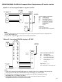
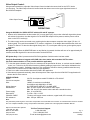
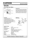
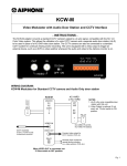
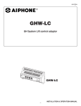
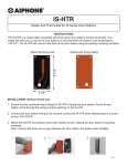
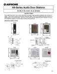
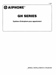
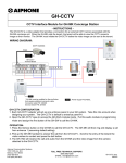
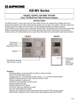
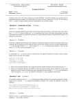
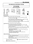
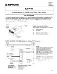
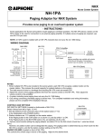
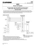
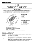
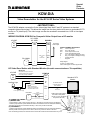
Special
Order
Products
KCW-D/A
Video Demodulator for the KC & GF Series Video Systems
- INSTRUCTIONS The KCW-D/A adaptor converts the 2-wire video signal from the KC and GF systems to a standard
composite video output signal. This allows the image from the door station to be seen on a standard CCTV
monitor or TV (video input). The video image can also be recorded if connected into a VCR or time lapse
recorder.
WIRING DIAGRAM: KCW-D/A for Composite Video Output from a KC monitor
KC-DAR
KC-1GRD/
KC-1HRD
KCW-D/A
A1
A2
1A1
1A2
DA1
DA2
b
E
DV+
DV-
Center cond. to
DV+
Braid to DV-
PS-2420UL
+
-
+
-
+
-
Composite
video output
KCW-D/A TERMINAL DEFINITIONS:
DA1
2-Wire input from
DA2
KC or GF monitor
DV+
Coax output: Center cond.
DVCoax output: Braided shield
b
Pos. 10V Output for Relay (KC Only)
E
Neg. 10V Output for Relay (KC Only)
+
Positive 24V DC
Negative
Output Signal:
75 ohm, 1V peak-to-peak.
Coax: Solid copper core with copper braid.
KC Video Door Station with Standard Monitor (No audio communication or Tilt capabilities)
IMPORTANT:
KC-DAR
A1
A2
CN3 speaker microphone connector
inside KC-DAR must be unplugged to
prevent the possibility of feedback.
KCW-D/A
RY-PA
Auxiliary Light
NOTE:
Relay will activate and
auxiliary light will illuminate
while the KC-DAR is active.
DA1
DA2
b
E
DV+
DV-
Standard CCTV
Monitor
To standard monitor
or monitor input on a
video switcher.
Center conductor to
DV+
Braid to DV-
To Aux Light Power Supply
PS-2420UL
+
TO POWER THE CAMERA:
(1) WHEN IN USE
Switch
(not supplied by Aiphone)
+
-
Solder jumper wire between
two holes in land pattern.
(JP101 A-to-A JP102 B-to-B
Component side view)
- Install a switch or relay contact in series with the "+" terminal from the power supply (see diagram).
- Solder a jumper between points labeled AA & BB on the KCW-D/A main PC board (see illustration).
This allows the camera to be activated manually, or when relay contact is activated.
(2) CONTINUALLY
- Solder a jumper between points labeled AA & BB on the KCW-D/A main PC board (see illustration).
This will provide continuous power to the camera, which may cause the camera to be warm.
Note: Continually powered, the overall life of the camera will be reduced and condensation may occur.
Pg. 1
WIRING DIAGRAM: KCW-D/A for Composite Video Output when any GF monitor is active
Method 1: Connecting KCW-D/A to a specific monitor
GF-1MD/
GF-1MDK
GF-VBC/GF-4Z
KCW-D/A
B1
B2
B1
B2
DA1
DA2
GF-BC
KCW-D/A TERMINAL DEFINITIONS:
DA1
2-Wire input from
DA2
KC or GF monitor
DV+
Coax output: Center cond.
DVCoax output: Braided shield
b
Not functional in GF System
E
Not functional in GF System
+
Positive 24V DC
Negative
b
E
R1
R2
R1
R2
Composite
video output
Center cond. to
DV+
Braid to DV-
DV+
DV-
24V DC
+
-
Output Signal:
75 ohm, 1V peak-to-peak.
Coax: Solid copper core with copper braid.
+
-
Notes:
1.Since the video signal is common throughout the system, video will be present from the KCW-D/A when
any GF-1MD monitor is on.
2. Any 24V DC, 1A power supply can be used to power the KCW-D/A.
Method 2: Connecting KCW-D/A directly to GF-VBC
GF-VBC
GF-VA
A1
A2
In 1
Out 1
A1
A2
B1
B2
In 2
Out 2
A1
A2
B1
B2
In 3
Out 3
A1
A2
B1
B2
In 4
Out 4
A1
A2
B1
B2
In 5
Out 5
A1
A2
B1
B2
Composite
video output
KCW-D/A
Center cond. to
DV+
Braid to DV-
DV+
DVb
E
Out 6
PS-2410LC
B1
B2
DA1
DA2
+
-
+
-
+
-
KCW-D/A TERMINAL DEFINITIONS:
DA1
2-Wire input from
DA2
KC or GF monitor
DV+
Coax output: Center cond.
DVCoax output: Braided shield
b
Not functional in GF System
E
Not functional in GF System
+
Positive 24V DC
Negative
Output Signal:
75 ohm, 1V peak-to-peak.
Coax: Solid copper core with copper braid.
Notes:
1. Video will be present from the KCW-D/A when any entrance panel is on, broadcasting video through all
of the outputs of the GF-VBC. The KCW-D/A can be connected to any unused output.
2. KCW-D/A can be connected to any of the six outputs on the GF-VBC, including those being
connected to GF-4Z, GF-1MD or GF-1MDK.
3. The KCW-D/A can also be connected to a GF-4Z. Wire to an output as above, but make
sure additional wires are run to the KCW-D/A for power.
Pg. 2
Video Output Control:
Using a small screwdriver, adjust the Video Output Control to obtain the correct level for the CCTV device
you are using. The Video Output Control is located under the rubber cover on the upper right hand corner of
the KCW-D/A faceplate.
Video Output Control
Lo
Hi
OPERATIONS
Using the KCW-D/A for VIDEO OUTPUT with the KC and GF systems:
1. When a call is initiated from the door station (KC) or entry panel (GF), the monitor called will ring and the picture
will activate. At that time, the video signal out of the KCW-D/A adaptor will be present, and the picture can be
seen on the CCTV monitor(s).
2. The video output can be connected to any receiving device that accepts a composite video signal (75 ohm, 1V
peak-to-peak). This could be a standard CCTV monitor, multiplexer, or an adaptor that modulates the video onto
a cable TV channel. To take the video signal directly into a TV, use a spare video input or go through the proper
modulator.
NOTES:
KC System Only: When the MONITOR button on any Monitor is pressed, the video will turn on for approximately 30
seconds, and video signal will be sent to the monitor via the KCW-D/A.
GF System Only: Video is present at the KCW-D/A regardless of which monitor has been called.
Using the Demodulator to integrate a KC-DAR video door station with a standard CCTV monitor:
(No audio communication or Tilt is possible with this application.)
1. To view the camera location at any time, the camera must be powered at all times, or a switch must be installed
to turn it on. To do this, the PC board must be modified by adding a jumper wire in the location indicated on the
wiring diagram on page 1. Soldering is required. This modification should be done by qualified technicians only.
2. There is no Tilt control of the KC-DAR camera in this application.
3. There is no audio communication with the KC-DAR in this application.
4. If the camera is powered continually, there will always be a video output from the KCW-D/A.This application will
shorten the life of the camera.
SPECIFICATIONS:
Power:
Current consumption:
Wire:
Wiring distance:
Demodulator:
Power supply:
Dimensions:
COAXIAL CABLE:
DC resistance:
24V DC. Use Aiphone model PS-2420UL or PS-2410LC.
500mA
18AWG, 2-conductor non-shielded
Use Aiphone wire #841802 or 871802
ALL DISTANCES ARE WITH 18 AWG WIRE.
Max. 30' from monitor when used for video output.
Max. 330' from KC door station when used with a standard monitor.
Max. 16' to KCW-D/A
5-1/2"H x 3"W x 1-1/2"D
75 ohms, solid copper center conductor, copper braid, 95% coverage.
Max. 15W per 1000 feet
Note:
Only information pertaining to the connection and operation of the KCW-D/A and connection of a standard video monitor is included
here. For complete installation, wiring, and operational information, please refer to the appropriate Installation Manual.
Aiphone Communication Systems
1700 130th Ave. N.E.
Bellevue, WA 98005
(425) 455-0510
FAX (425) 455-0071
Toll Free Technical Support:
1-800-692-0200
FAX: 1-800-832-3765
E-mail [email protected]
Pg. 3
KCW-D/A Instr.
1103bkjs